

Page 1
In-car radio
With CD
Instruction manual
ICS105
Page 2

ICS105
Instruction Manual
Congratulations on purchasing the Alba ICS-105 In-Car Head Unit.
GLOSSARY
We trust that this product will give you hours of listening pleasure,
and provide years of unparalleled performance. As with any ne w
electrical produ ct please be patient and allo w 36 hou rs of use
before all co mponents have acclimatized th emselves with yo ur
surroundings and found their optimum working temperature.
Please read these instructions before you install or operate the unit.
Please retain these instructions. Manufacturer of this u
principle of constant improvement and is not held responsible for
any changes that are made to the unit nor accepts any liabilities for
these changes . A fitting service is available if required , leaflet
enclosed.
nit follows a
FM Frequency Modulated Audio Broadcasting
RDS Radio Data System
SNR Signal to Noise Ratio
1
Page 3

CONTENTS
Installation ................................................................................................ 3
Take out screw before installation .............................................................. 3
DIN Front-Mount (Method A)...................................................................... 3
I nstalling the unit..................................................................................... 3
Removing the unit................................................................................... 5
DIN Rear-Mount (Method B) ...................................................................... 5
Using the detachable front panel ........................................................... 6
Wiring Connection ................................................................................... 7
Location of keys....................................................................................... 8
Basic operation .......................................................................................... 9
Switching on/off the unit ........................................................................... 9
Faceplate release..................................................................................... 9
Sound adjustment .................................................................................... 9
System setting.......................................................................................... 9
Loudness.................................................................................................. 10
Set the clock............................................................................................. 10
Display information................................................................................... 10
Equalization.............................................................................................. 10
ESP function............................................................................................. 10
Auxiliary input ........................................................................................... 10
Reset function .......................................................................................... 10
Radio operation .......................................................................................... 11
Switching to radio mode ......................................................................... 11
Selecting the frequency band ................................................................. 11
Selecting station ..................................................................................... 11
Automatic memory storing and program scanning ................................. 11
Station storing......................................................................................... 11
RDS operation ........................................................................................ 12
CD operation .............................................................................................. 12
Switching to CD mode ............................................................................ 12
Selecting tracks ...................................................................................... 12
Pausing playing ...................................................................................... 12
Previewing tracks ................................................................................... 12
Repeating tracks..................................................................................... 12
Playing tracks in random ........................................................................ 12
Ejecting a disc ........................................................................................ 12
Disc notes ............................................................................................... 13
Specification ............................................................................................. 13
Trouble shooting ...................................................................................... 14
Contact details.......................................................................................... 14
Product Guarantee ................................................................................... 15
2
Page 4
INSTALLATION
Notes:
Choose the mounting location where the unit will not interfere with t he normal
driving function of the driver.
Before finally installing the unit, connect the wiring temporarily and make sure it
is all con nected up properly the n c heck that the unit an d the system work
properly.
Use only the parts included with the unit to ensure proper installation. The use
of unauthorised parts can cause malfunctions.
Consult with your ne arest d ealer i f installation r equires the drilling of holes or
other modifications of the vehicle.
Install the unit where it do es not g et in the driver’s way and cannot injure the
passenger if there is a sudden stop, like an emergency stop.
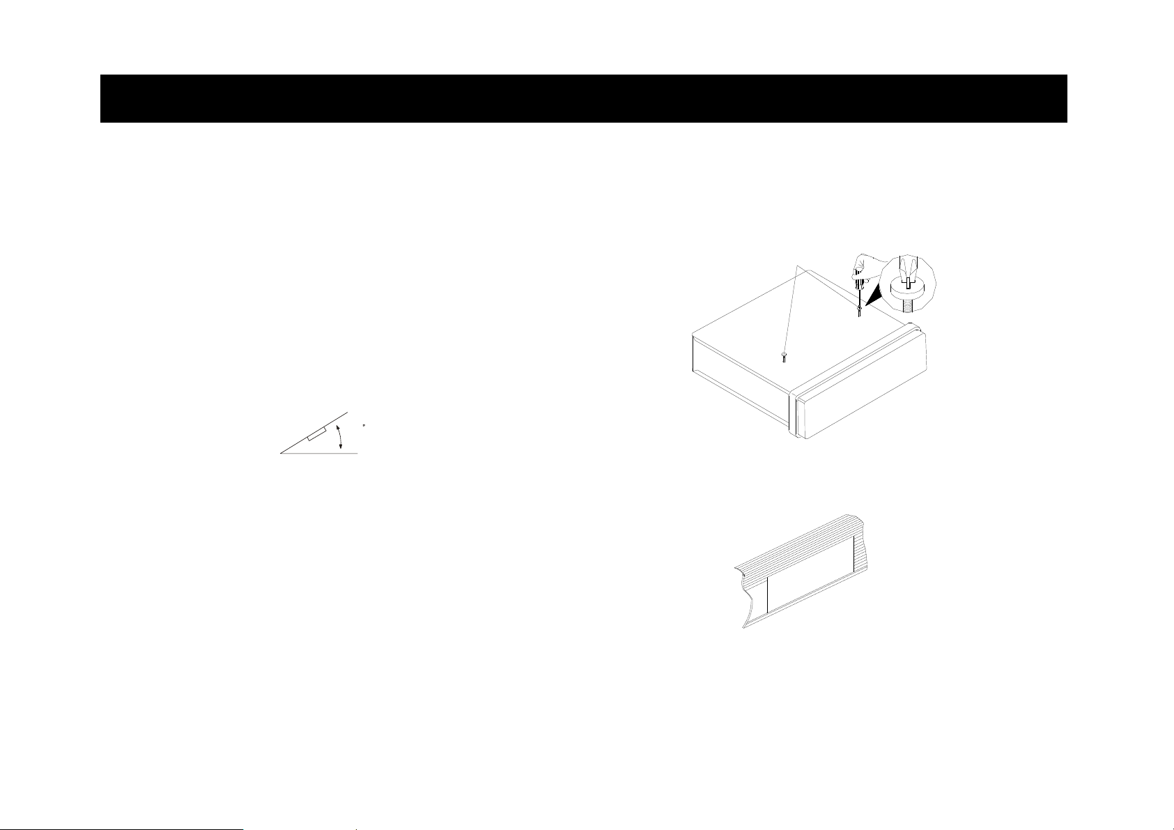
If inst allation angle exceeds 3 0° from h orizontal, th e un it m ight not give it s
optimum performance.
Avoid installing the unit where it would be subject to high temperature, such as
from direct sunlight, or hot air, from the heater, or where it would be subject to
dust, dirt or excessive vibration.
DIN FRONT/REAR-MOUNT
This unit can be installed either from “Front” (conventional DIN Front-mount) or
“Rear” (DIN Rear-mount installation, utilizing threaded screw holes at the sides of
the unit chassis). For details, refer to the following illustrated installation methods.
30
TAKE OUT TRANSPORT SCREWS BEFORE INSTALLATION
Before installing the unit, please remove the two transport screws as indicated in
the following diagram.
DIN FRONT-MOUNT (Method A)
Installation Opening
This unit can be installed in any dashboard having an opening as shown below:
Installing the unit
Be sure you test all connections first, and then follow these steps to install the unit.
1. Make sure th e ignition is turned o ff, a nd then discon nect the ca ble fr om the
vehicle battery’s negative (-) terminal.
Take out screw
before installation.
3
Page 5
INSTALLATION
2. Press the release button on the fro nt panel and remove the control panel (see
the steps of “removing the front panel”).
3. The outer trim ring is secured to the radio by side clips. Lift off the outer trim
ring in a horizontal direction from one of its sides to release the clips.
4. Th
e t wo suppli ed keys release the t abs inside the unit’s sl eeve s o y ou can
remove it. Insert the keys as far as they will go (with the notches facing up) into
the appropriate slots at the middle left and right sides of the unit. Then slide the
sleeve off the back of the unit.
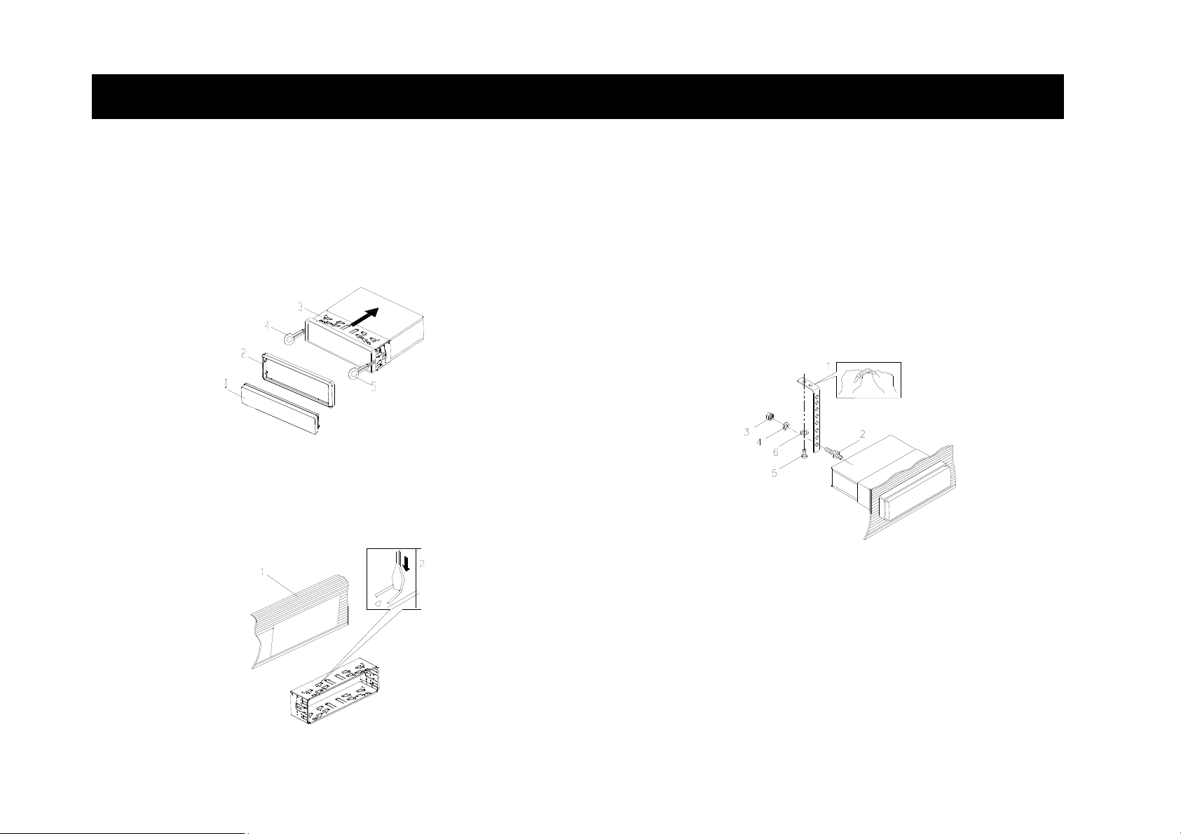
(1) Front panel; (2) Outer trim ring; (3) Sleeve; (4) L key; (5) R key
5. Mount the sl eeve by in serting it in to the ope ning of th e dash board a nd b end
over the tabs located around the sleeve with a screwdriver. Not all t abs will be
able t o make contact, so examine which ones will be most effective. Bending
over the appropriate tabs behind the dashboard to secure the sleeve in place.
6. Connect t he wire h arness an d t he a ntenna an d be c areful n ot to pinch a ny
wires or cables.
7. Slide the unit into the sleeve until it locks into place.
8. To further secure the unit, use the supplied metal strap to secure the back of the
unit in place. Use th e supplie d hardware (M5 He x Nut a nd Spring Washer) to
attach one end of the strap to the mounting bolt on t he ba ck of the unit. If
necessary, bend the metal strap to fit your vehicle’s mounting area. Then use
the supplied hardware (self-tapping screw and plain washer) to attach the other
end of metal strap to a solid metal part of the vehicle under the dashboard. This
strap also helps ensure proper electrical grounding of the unit.
Note: - In stall the short thread end of the mounting bolt to the back of the unit
and the long thread end to the dashboard.
(1) Metal Strap; (2) Mounting Bolt; (3) Hex Nut;
(4) Spring Washer; (5) Self Tapping Screw; (6) Plain Washer
10. Reconnect the cable to the vehicle battery’s negative (-) terminal. Then
replace the outer trim ring and install the unit’s front panel (see the steps of
“Installing the front panel”).
(1) Dashboard (2) Tabs
4
Page 6

INSTALLATION
Removing the unit
1. Make sure the i gnition is turned off, and then disconnect the cable from th e
vehicle battery’s negative (-) terminal.
2. Remove the metal strap attached the back of the unit (if attached).
3. Press the release button to remove the front panel.
4. The outer trim ring is secured to the radio by side clips. Lift off the outer trim
ring in a horizontal direction from one of its sides to release the clips.
5. Insert both of the supplied keys into the slots at the mi ddle left and right sides
of the unit then pull the unit out of the dashboard.
Side View showing
Screw Holes marked
T, N
Screw
Factory Radio
Mounting Bracket
DIN REAR-MOUNT (Method B)
If your vehicle is a Nissan, Toyota, follow these mounting instructions.
Use the screw holes marked T (Toyota), N (Nissan) located on both si des of the
unit to fasten th e un it to the factor y radio mountin g bra ckets supplied with y our
vehicle.
Screw
Dashboard or Console
To fit the unit into the factory radio mounting brackets.
Align the s crew ho les on the bracket with the scre w hol es on the unit, and then
tighten the screws (5x5mm) on each side.
Note: T he outer trim ring, sleeve an d t he metal st rap are not used for method B
installation.
5
Page 7

DETACHABLECONTROLPANEL(DCP)
REMOVING THE FRONT PANEL
1. Turn the Power Off
2. Press the DCP release button.
3. Re move the DCP
Keep front panel in the protective case.
INSTALLING THE FRONT PANEL
To install the front panel, insert the panel into the housing and make sure the panel
is properly installed. Otherwise, abnormalities may occur o n the display or some
keys may not function properly.
MUTE
1. Attach the panel at the right side first, at point 1 on the main unit while
2. Then press the left side of the DCP back onto the main unit until a
PRECAUTIONS WHEN HANDING
1. Do not drop the front panel.
2. Do no t p ut pre ssure on the display or control b uttons when det aching or
re-installing the front panel.
3. Do not t ouch the contacts on the front panel or on the main unit bo dy. It m ay
result in poor electrical contact.
4. If any dirt or foreign substances a dhere t o the contacts, t hey can be removed
with a clean dry cloth.
5. Do not expose the front panel to high temperatures or direct sunlight.
6. Avoid any volatile agents (e.g. benzene, thinner or insecticides) from touching
the surface of the front panel.
7. Do not attempt to disassemble the front panel.
MUTE
holding the DCP at point 2 (as shown on the diagram).
“click” sound is heard.
6
Page 8
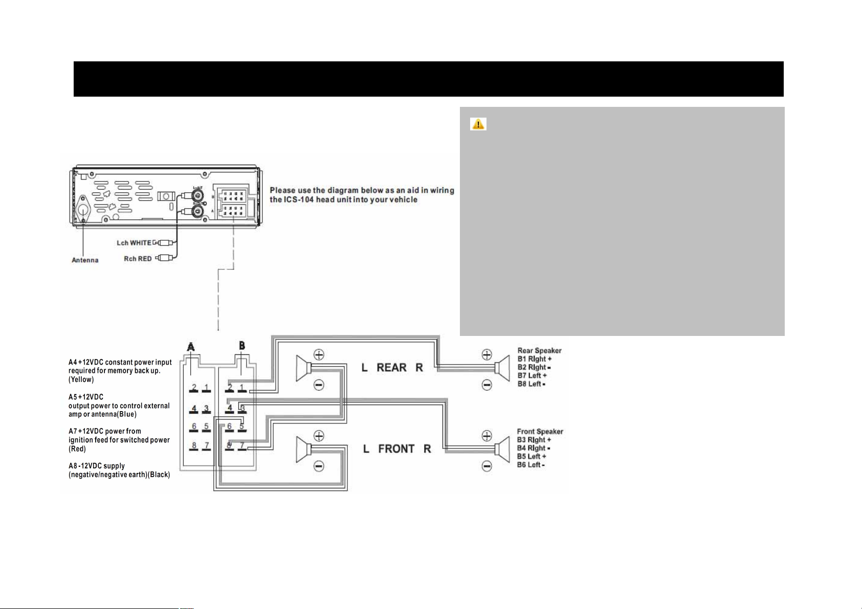
WIRINGCONNECTIONS
FOR 4 x 40W SYSTEM
FOR 4 x 40W SYSTEM
* Cables not supplied
CAUTION
12V DC NEGATIVE GROUND
Do not connect any speaker wires to the metal body or chassis of the vehicle
Do not connect the speaker common (-)
Never bridge or combine the
speaker wires to each other
speaker wire outputs,take care not to short out
wires to each other
Connect each speaker wire directly
to each speaker terminal
WARNING: Do not interchange the connections of the wiring.
Some carm odels may require special additional power h arness.
Contact your authorised cardealer before installing
this unit.
7
7
Page 9
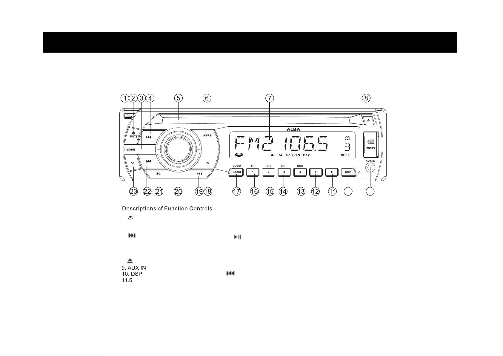
LocationOFKEYS
1. (DCP release button)
2. POWER/ MUTE
3. MODE
4.
5. disc slot
6. AS / PS
7. LCD
8. (Eject button)
12. 5
13. 4 / RDM
14. 3 / RPT
15. 2 / INT
16. 1 /
17. BAND / LOUD
18. TA
19. PTY
20. VOL / SEL
21. EQ
22.
23.AF
910
8
Page 10

BASICOPERATION
TURNING ON/OFF THE UNIT
Press any key (except
is on, press and hold the
FACEPLATE RELEASE
Press
SOUND ADJUSTMENT
Press th e SEL button ( 20) briefly t o select the desired adjustment mod e. T he
adjustment mode will change in the following order:
(Bass) (T reble) (Balance) ( Fader)
By rotating the volume knob (20) clockwise or counter-clockwise, it is possible to
adjust the desired sound quality.
SYSTEM SETTING
Press an d ho ld the SEL bu tton ( 20) on the front panel to enter syst em sett ing
mode. Then briefly press the SEL button (20) to select the item you want to change
and rotate the volume knob (20) to change the corresponding setting.
P-V
1)
The max volume value when y ou turn on the unit. If the set volume level is lo wer
than th
on the unit the volume will maintain the last volume value. If the set volume level is
higher than the value you have set, when you tur n off the unit then th e next time
you turn on the unit the volume value will be at the max volume level you have set.
2) BEEP ON/OFF
Use the volume knob (20) to set Beep sound ON or OFF.
button (1) to detach the removable faceplate.
BAS → TRB → BAL → FAD
OL
e value
you have set, when you turn off the unit then the next time you turn
and button) to turn on the unit. When the system
/MUTE button (2) to turn off the unit.
3) AREA EUR/USA/ASI/S-A/JPN/OIR
In rad io mode, Use the volume kn ob ( 20) to set the dif ferent ar ea
frequency spacing.
4) TA ALARM/SEEK
Use the volume knob (20) to set TA ALARM or TA SEEK.
Traffic announcements
■ TA SEEK: With activated TA function the unit searches for a station with
traffic announcements.
■ TA ALARM: No au tomatic station search. The unit sounds a beep tone if no
traffic information is recei ved and NO TP/TA is displayed. SEE K P I i s
displayed if the selected station does not transmit an RDS signal.
5) PI SOUND/MUTE
Use the volume knob (20) to set PI SOUND or PI MUTE.
Moving into an area where two stations with identical AF, but different Pl code
(PI = program inf ormation) are re ceived reception w ill des tabilise. In thi s
situation you have two options:
■ PI SOUND: To change stations the other station is played for less than one
second.
■ PI MUTE: The other station is muted.
6) RETUNE L/S
Use the volume knob (20) to set RETUNE L or RETUNE S.
Delay f or a utomatic search with tr affic announcements and/or pro gram
information:
■ S (short) after approx. 30 seconds;
■ L (long) after approx. 90 seconds.
9
Page 11

BASICOPERATION
7) MASK DPI/ALL
Use the volume knob (20) to set MASK DPI or MASK ALL.
Setting to mask station during search:
■ DPI : Alternative frequencies with different Pl code a re excluded from the
search.
■ ALL : Alternative frequencies with different Pl code and no RDS information
with high signal level are excluded from the search.
8) EON TA DX/LOCAL
Use the volume knob (20) to set EON TA DX or LOCAL.
9) REG ON/OFF
Use the volume knob (20) to set REG ON or OFF.
Some stations split t heir progr ams at c ertain ti mes into regional programs
with different contents.
- To play only the regional programs of the station when REG ON.
- To return to the nationwide program when REG OFF.
10) TA VOL
Use the volume knob (20) to adjust the TA volume value.
LOUDNESS
Press BAND/LOUD button (17) for sev eral seconds to en hance the bass o utput.
ress it for se
P
SET THE CLOCK
Press the DSP button (10) until the clock is shown on the display. Then press and
hold the DSP button u ntil the cl ock fl ashes. T hen pre ss
change the minutes and
Note. T he Clock w ill automatic ally up date w hen tuned to and receives a n RDS
signal .
veral seconds again to release this function.
button (4) to
button (22) to change the hours.
DISPLAY INFORMATION
Press DSP button (10) to toggle through each of the display modes. Such as the
clock, PTY group, Band, station name and frequency.
Note: The information displayed is mode depend
EQUAL
Press EQ b utton ( 21) to tur n on equalization fun ction and to s elect desired audio
mode. There are five kinds of mode as below:
MUTE
Press
the sound.
ESP FUNCTION
CD shockproof protection with approximately ten seconds memory.
AUXILIARY INPUT
The unit c an be con nected to a portable aud io player through the auxiliary input
jack (9) on the front panel. Once connected, you can press the MODE button (3)
on the front panel to switch the mode
RESET FUN
Press and hold both 1/>/II button (16) and MODE (3) button for 2 seco nds. The
unit will be reset. Use the RESET function for the following reasons:
- Initial installatio
- All the function buttons do not operate.
- Error symbol on the display.
Note: if in press ing and h olding both 1/> /II button (16) and MODE (3), the unit
does not reset, please use a cotton swab soaked in isopropyl alcohol to clean the
metal contacts of the connector on the rear of the front panel and the connector on
the front of the head unit.
IZATION
FLAT→CLASSICS→POP M→ROCK M→DSP OFF
/MUTE button (2) briefly to mute the sound. Press it again to resume
to AUX IN mode.
CTION
n of the
unit when
all wiring is
ent
completed.
10
Page 12

BASICOPERATION
RADIO OPERATION
SWITCHING TO RADIO MODE
Press MODE button (3) br iefly to sele ct ra dio mode, the band / frequency or
station name will be displayed.
SELECTING THE FREQUENCY BAND
At radio mod e, press BAND/LOUD button (17) briefly to select the desired band.
The reception band will change in the following order:
FM1 → FM2 → FM3 → MW1→ MW2
SELECTING STATION
Press
function.
until “ MANUAL” a ppears o n the display, the ma nual tuning mode is sel ected. In
this mode you can step up/down the frequencies one by one to search for a station.
If both buttons have not been pressed for several seconds, they will return to seek
tuning mode and “AUTO” appears on the display.
Note: When TA function is on, the seek operation will search only for TA programs.
And when PTY is selected but not TA, then a PTY search will occur.
button ( 4) o r but ton ( 22) briefly to activ ate au tomatic seek
It will search up/down a station automatically. Press for several seconds
AUTOMATIC MEMORY STORING & PROGRAM SCANNING
- Automatic memory storing
Press AS/PS b utton (6) for several se conds, the ra dio se arches from the
current frequency a nd ch ecks t he signal stren gth u ntil a on
finished, the 6 strongest st ations are stored into the c orresponding p reset
number button.
- Program scanning
Press AS/PS button (6) briefly to scan preset stations. Each preset station will
blink for 5 seconds while playing that station before moving on to the next station.
After al
Pressing AS/PS button at any time will halt the scan.
STATION STORING
Press preset 1 to 6 butto ns (11 – 16) for seve ral s econds t o sto re th e c urrent
station into the number button. Press any one of the preset 1 to 6 buttons (11 – 16)
to select a station memory location.
LOC/DX (LOCAL/DISTAN
and hold PTY button (19) to activate the LOCAL function. Press a nd hold it
Press
again to return to DX (Distance) function.
ets have been scanned the radio will return to the first preset station.
l pres
CE)
e-cycle
search i s
11
Page 13

RDSEXPLAINEDCDOPERATION
RDS (RADIO DATA SYSTEM) OPERATION
- Settin g RDS mode
Press AF button (23) to switch on or off the AF mode.
Whenever AF is switch on, symbol “AF” appears on the display.
- Using PTY to Select Program
■ Pre ss PTY button (19) briefly to select the PTY group. Then rotate the volume
knob ( 20) to sel ect t he PT Y program and pr ess
button (22) to search.
■ When PTY ON, press PTY button (19) again to cancel the PTY function.
- Listen ing to Traffic Announcement
Press TA button ( 18), the uni t will search Traffic Announcement autom atically.
Press TA button (18) again will exit TA mode.
The RDS data used is AF, TP, TA, EON and PTY dat
AF: Alternative
Frequency list of broa dcasting stations transmitting the same
program
TP: Traffic Program Identification
Identification data for traffic information-broadcasting station
TA: Traffic Announcement Identification
Identification data showing if traffic information is being transmitted
EON: Enhanced Other Networks Information
Broadcasting in formation on AF, T P, TA, etc, relati ng to networks
other than the network used for current reception
PTY: Program Type Code
Contents of programs such as news, light music, sports etc
Frequencies
button ( 4) r
a.
SWITCHING TO CD MODE
If there is no CD disc inserted in the drive:
Gently ins ert the d isc w ith the pri nted si de upper most into t he CD com partment
until you feel some resistance. The disc is drawn into the drive automatically. Disc
playback begins.
If a CD disc is already inserted in the drive:
Keep pressing MODE button (3) repeatedly until the CD mode display appears.
SELECTING TRACKS
Press
following track. Track number shows on display.
Press and hold
Disc play starts from when you release the button.
PAUSING PLAYING
Press
PREVIEWING TRACKS
Press INT button (15) to play first several seconds of each track on the current disc.
Press again to stop intro and listen to track.
REPEATING TRACKS
Press RPT butt
repeat all tracks.
PLAYING TRACKS IN RANDOM
Press RDM button (13) to play all tracks on CD in random order. Press again to
cancel the function.
EJECTING A DISC
Press
button (22) or button ( 4) to m ove to th e previous tra ck or the
button (22) or button (4) to fast reverse or fast forward.
button (16) to pause the player. Press it again to resume play.
on (
14) to continuously re
button (8) to stop CD playing and eject the disc from the disc slot (5).
peat the sam
e track. Press it again to
12
Page 14

CAREMAINTENCESPECIFICATIONS
DISC NOTES
A. Notes on discs:
1. Attempting to us e non-standard shape discs may damage the unit. Be sure to
use round shape CD discs only for this unit.
2. Do not stick paper or tape, etc, onto the label side or the recording side of any
discs, as it may cause a malfunction.
3. Dirt, dust, scratches and warping discs will cause faulty operation.
B. Notes on CD-Rs (recordable CDs)/CD-RWs (rewritable CDs):
1. Be sure to use discs with following marks only for the unit to play:
2. The unit cannot play a CD-R and CD-RW that is not finalised. (Please refer to
the ma nual of your CD-R/CD-RW recorder or CD-R/CD-RW software for more
information on finalisation process).
3. Dep ending o n the recordi ng status, c onditions of the disc and th e e quipment
used f or t he r ecording, so me CD-Rs/CD-RWs may not be played on t his unit.
(See *1)
*1: For reliable play back, please note the following recommendations:
a. Use CD-RWs with speed 1x to 4x and write with speed 1x to 2x.
b. Use CD-Rs with speed 1x to 8x and write with speed 1x to 2x.
c. Do not play a CD-RW which has been written for more than 5 times.
ReWritable
GENERAL
Power Supply Requirements : DC 12 Volts, Negative Ground
Chassis Dimensions : 178 (W) x 160 (D) x 50 (H)
Tone Controls
- Bass (at 100 Hz) : ±10 dB
- Treble (at 10 kHz) : ±10 dB
Maximum Output Power
Current Drain : 15 Ampere (max.)
CD PLAYER
Signal to Noise Ratio : More than 55 dB
Channel Separation : More than 50 dB
Frequency Response
RADIO
FM
Frequency Coverage 87.5 to 108 MHz
IF 10.7 MHz
Sensitivity (S/N=30dB) 10 dBuV
Stereo Separation >25dB
Frequency Coverage 522 to 1620 kHz
IF 450 kHz
Sensitivity (S/N=20dB) 36 dBuV
: 4 x 40 watts maximum power
: 40Hz – 18 kHz
MW
13
Page 15

TROUBLESHOOTINGCONTACTDETAILS
Before going through the checkli st, che ck the wiring c onnections. If any o f the
problems persist after following the checklist, consult your nearest service dealer.
Symptom Cause Solution
No power.
Disc cannot be
loaded or ejected.
No sound.
Sound skips.
The operation keys
do not work.
work. The radio
station automatic
selection does not
work.
The car ignition switch is not
on.
The fuse is blown. Replace the fuse.
CD disc present inside the
player.
Disc inserted upside down. Insert the CD with the label
CD is extremely dirty or
defective.
Temperature inside the car is
too high.
Condensation. Leave the player off for an hour
Volume is at minimum Adjust volume to the desired
Wiring is not properly
connected.
The installation angle is
more than 30 degrees.
The disc is extremely dirty or
defective.
The built-in microcomputer is
not operating properly due to
noise.
The antenna cable is not
connected.
The signals are too weak. Select a station manually.
If the power supply is connected
to the car accessory circuits, but
the engine is not moving, switch
the ignition key to “ACC”.
Remove the disc in the player,
and insert a new one.
facing upward.
Clean the disc or try to play a
new one.
Cool off inside of car until the
temperature returns to normal.
or so, and then try again.
level.
Check wiring connections.
Adjust the installation angle to
less than 30 degrees.
Clean the compact disc, and
then try to play a new one.
Press the RESET button.
Front panel is not properly fixed
into its place.
Insert the antenna cable firmly. The radio does not
We trust you are completely satisfied with this p roduct from Argos Ltd, ho wever
please feel free to contact us if you experience any difficulties, or if you would like
to express your views regarding our products.
Please write to:
Customer Services
Argos Ltd
489-499 Avebury Boulevard
Saxon gate West
Central Milton Keynes
MK9 2NW
Telephone No.: 0870 600 3030
Through the process of continuous improvement, Argos Limited reserves the right
to change or alter specifications without prior notice. E&OE
14
Page 16

Product guarantee
This product is guaranteed for twelve months from the date of original purchase.
Any defect that arises due to faulty materials or workmanship will either be replaced,
refunded or repaired free of charge where possible during this period by the dealer from
whom you purchased the unit.
The guarantee is subject to the following provisions:
• The guarantee does not cover accidental damage, misuse, cabinet parts, knobs or consumable items.
• The product must be correctly installed and operated in accordance with the instructions contained in
this manual.
• It must be used solely for domestic purpose.
• The guarantee will be rendered invalided if the product is re-sold or has been damaged by inexpert repair.
• Specifications are subject to change without notice.
• The manufacturer disclaims any liability for the incidental or consequential damages.
• The guarantee is in addition to, and does not diminish your statutory or legal rights.
Guarantor: Argos Limited
489 - 499 Avebury Boulevard
Central Milton Keynes MK9 2NW
 Loading...