

Alarm SAF BN4-002-PD8-UL, BN4-000-PD8F-UL, BN4-000-PD8-UL, BN4-002-PD8F-UL, BN6-000-PD8F-UL Operating And Installation Instruction Manual
...
AlarmSaf
65A Industrial Way, Wilmington, MA 01887-3499, USA, Toll Free: 800-987-1050, Voice: 978-658-6717, Fax: 978-658-8638, www.alarmsaf.com
Beacon Power Management System Installation Manual
This Installation manual is made up of the following separate Installation Instructions for the Power Supply
and Power Distribution Module.
52-296 - Installation Instructions for Beacon Power Supply - pp. 2-28
52-325 - Installation Instructions for Beacon Power Supply - Addendum A - p. 29
52-326 - Installation Instructions for PD Module - p. 30-43
Model Numbers: Order Numbers:
BN4-000-PD8F-UL 10003
BN4-000-PD8-UL 10002
BN4-002-PD8F-UL 10006
BN4-002-PD8-UL 10005
BN6-000-PD8F-UL 10015
BN6-000-PD8-UL 10014
BN6-002-PD8F-UL 10018
BN6-002-PD8-UL 10017
BN10-002-PD8F-UL 10053
BN10-002-PD8-UL 10054
BN10-003-PD8F-UL 10056
BN10-003-PD8-UL 10055
*May also be used for any Beacon Power Management System that
includes any combination of the following boards:
Model Numbers: Order Numbers:
PD8F-UL 10042
PD8-UL 10041
BN4-000-UL 10001
BN6-000-UL 10013
BN8-000-UL 10025
BN10-000-UL 10034
BN4-004-PD8F-UL 10062
BN10-004-PD8F-UL 10079
BN8-002-PD8-UL 10060
BN64-004-PD32-UL 10074
BN1010-004-PD16-UL 10059
BN1010-004-PD16F-UL 10083
BN1010-003-PD16-UL 10090

Beacon Power Supply Installation Instructions
2.8.2012
Beacon Power Supply
Operating and Installation
Instruction Manual
Model: BNx000
AlarmSaf 65A Industrial Way, Wilmington, MA 01887 978 658 6717 www.alarmsaf.com
52-296 Rev B05
Page 1 of 27

Beacon Power Supply Installation Instructions
2.8.2012
I. Warnings and Notices
I. WARNING - To reduce the risk of fire or electric shock, do not expose this
product to rain or moisture.
II. WARNING – Risk of electric shock. Installation and service should be made by
qualified service personnel and should conform to all local codes.
III. WARNING – Read the instruction manual to avoid personal injury or property
damage
IV. NOTICE - This equipment shall be installed in a manner which prevents
unintentional operation from employees or other personnel working about the
premises, by falling objects, by building vibration and by similar causes
V. NOTICE - This equipment is not intended for use within the patient care areas
of a Health Care Facility
AlarmSaf 65A Industrial Way, Wilmington, MA 01887 978 658 6717 www.alarmsaf.com
52-296 Rev B05
Page 2 of 27

Beacon Power Supply Installation Instructions
Section
Page
I. Warnings and Notices
21
Introduction
4
2 Applicable Standards / Documents
53
System Overview
6-13
3.1 Electrical Ratings and Specifications
6
3.2 BNx000 Con
nector Descriptions and Electrical Ratings
7
3.2.1
Terminal and
Connector
Illustration
8
3.3 AC Input Connection
9-10
3.4 A
ccessory
B
oard
Connectors
(ABC)
10
3.5
ABC Buss Voltage Selection
10-113.6
Output Terminals
113.7FAI Input Terminals
123.8Fault Reporting Terminals
134 Installation
14-164.1 Mounting
144.2 Wiring
15-165
Operating the BNx000
17-20
5.1 Output Voltage Selection
175.2 Jumper Settings
17-18
5.3 Visual Indicators
18-195.4 Troubleshooting
206 Specifications
216.1 Electrical Specifications
216.2 Temperature Specifications
216.3 Mechanical Specifications
21Appendix A
-
FAI Input
22-23
Appendix
B–About the Accessory Board Connector
24-26
Glossary
2
7
2.8.2012
Table of Contents
AlarmSaf 65A Industrial Way, Wilmington, MA 01887 978 658 6717 www.alarmsaf.com
52-296 Rev B05
Page 3 of 27

Beacon Power Supply Installation Instructions
2.8.2012
Section 1
Introduction
The Beacon Line of power supplies (BNx000) is an of off-line switching power supply product
line designed for use in the access control and fire industries by the Systems Integrator. They
accept several accessory boards designed to increase the functionality of the basic power
supply.
Field selectable output voltage of 12V or 24VDC
Units provide twice the current capability when set to 12VDC as at 24VDC. This is to
compensate for the typically double current draw of 12V devices such as mag locks.
Expandable with accessory boards via the ABC connector
All units can charge up to 38AH of battery while supplying full rated load
Full fault detection, including battery presence detection, and reporting via two form-C
relay contacts; AC fault and System Fault
Flexible FAI input for egress control or other functions. Accepts contact closure (NO or
NC), voltage input, reverse polarity voltage, or open collector input
FAI activation is transmitted to ABC connector for activation of FAI on compatible
accessory boards
Fault conditions monitored include:
Low or missing AC
High or low output / battery
Blown fuse
Missing battery
Reversed Battery
Internal Power Supply failure
Visual indicators include:
AC Presence (Green)
DC Output Presence (Green)
FAI Activated (Red)
Reversed Battery Fault (Yellow)
AC Fault (Yellow)
System Trouble (Yellow)
AlarmSaf 65A Industrial Way, Wilmington, MA 01887 978 658 6717 www.alarmsaf.com
52-296 Rev B05
Page 4 of 27

Beacon Power Supply Installation Instructions
2.8.2012
Section 2
Applicable Standards / Documents
NFPA Standards
NFPA 72 National Fire Alarm Code
NFPA 70 National Electrical Code
NFPA 731 Standard for the Installation of Electronic Premises Security Systems
US Standards
UL 294 Access Control System Units
UL 1481 Power Supplies for Fire Protective Signaling System
Other Standards
MEA Listed
California State Fire Marshal (CSFM) Listed
Applicable Local and State Building Codes
Requirements of the Local Authority Having Jurisdiction (LAHJ)
Other Applicable AlarmSaf Documents
52-351: CMB8(F) Accessory Board Installation Manual
52-352: MB8(F) Accessory Board Installation Manual
52-254: APD8(F) Accessory Board Installation Manual
52-326: PD8(F) Accessory Board Installation Manual
52-350: SPS4 Accessory Board Installation Module
Listing Compliance Note
This product carries an ETL Listing from Intertek for one or more of the standards listed above.
Intertek is recognized by the Occupational Safety and Health Administration (OSHA) as a
Nationally Recognized Testing Laboratory (NRTL) and accredited by the Standards Council of
Canada as a Testing Organization and Certifying Body. The ETL Listed Mark is recognized,
acknowledge and accepted by local inspectors and Authorities Having Jurisdiction (AHJs)
throughout North America as an accepted alternative to UL and as proof of product compliance.
For more information about the NRTL program, we encourage you to visit the OSHA Web site at
www.osha.gov.
AlarmSaf 65A Industrial Way, Wilmington, MA 01887 978 658 6717 www.alarmsaf.com
52-296 Rev B05
Page 5 of 27

Beacon Power Supply Installation Instructions
2.8.2012
Section 3
System Overview
3.1 Electrical Ratings and Specifications
Manufactured By
AlarmSaf
65A Industrial Way
Wilmington, MA 01887
Tel: 978.658.6717; 800.987.1050
www.alarmsaf.com
Model Numbers (Board Only)
BN4000, BN6000, BN8000, BN10000
Full product list available at www.alarmsaf.com
Electrical Ratings
Input Voltage All Models: 102-138VAC (120VAC Nominal) or 240VAC nominal (with proper
jumper selection, see page 18)
Input Power BN4000: 125W maximum
BN6000: 190W maximum
BN8000: 250W maximum
BN10000: 330W maximum
Output 12 or 24VDC nominal at:
BN4000: 4A (24V out) or 8A (12V out); 110W
BN6000: 6A (24V out) or 12A (12V out); 165W
BN8000: 8A (24V out) or 16A (12V out); 220W
BN10000: 10A (24V out) or 20A (12V out); 276W
Efficiency ~90%
Ripple <0.5% @ 12V output
Output Fuse Type BN4000: ATC10 (10 Amp)
BN6000: ATC15 (15 Amp)
BN8000: ATC20 (20 Amp)
BN10000: ATC25 (25 Amp)
Buss Select Fuse Type ATM15 (15 Amp) Miniature Automotive Blade Fuse
Product Use
When installed in accordance with all standards listed in Section 2 of this document, the Beacon
Line provides power for use with (but not limited to) fire or access control equipment such as
mag locks, door strikes, door holders, smoke dampers, four wire smoke detectors, card readers,
keypads, etc.
AlarmSaf 65A Industrial Way, Wilmington, MA 01887 978 658 6717 www.alarmsaf.com
52-296 Rev B05
Page 6 of 27

Beacon Power Supply Installation Instructions
Terminal /
System Fault Relay
-
Normally
Closed
2.8.2012
3.2 BNx000 Connector Descriptions and Electrical Ratings
Connector
P1
5-Pin AC Line connector
AC PWR CONNECT
P2 Accessory Board Connector (ABC) Output
TB1 - DC1 and DC2 Outputs
DC1+ DC1 Positive Output
DC1- DC1 Common Output
DC2+ DC2 Positive Output
DC2- DC2 Common Output
TB2 - DC3 and BAT Outputs
DC3+ DC3 Positive Output
DC3- DC3 Common Output
BAT+ Battery Positive Connection
BAT- Battery Common Connection
Description Rating
102-138VAC (120VAC Nominal) or
240VAC Nominal with appropriate jumper
setting (see page 18)
12 or 24VDC @ 14A Maximum or to
maximum rating of power supply
Full output current of supply - See Section
3.1 for ratings. Output is constant,
regardless of FAI input state
Full output current of supply - See Section
3.1 for ratings. Output deactivates upon
FAI Activation
Full output current of supply - See Section
3.1 for ratings. Output activates upon FAI
Activation
12 or 24VDC nominal - 38AH Maximum
TB3 - FAI Input
V+ Auxiliary Voltage Output 12VDC Nominal @ 15mA Maximum
L+
L+
LL-
Positive FAI Activation Terminals
Common FAI Activation Terminals
V- Auxiliary Voltage Common System DC Common
TB4 - Fault Contacts
SYS FLT - COM System Fault Relay - Common
SYS FLT - NC
SYS FLT - NO System Fault Relay - Normally Open
AC FLT - NO AC Fault Relay - Normally Open
AC FLT - NC AC Fault Relay - Normally Closed
AC FLT - COM AC Fault Relay - Common
9-33VDC @ 15mA Maximum
1A @ 24VDC
0.5A @ 120VAC
1A @ 24VDC
0.5A @ 120VAC
AlarmSaf 65A Industrial Way, Wilmington, MA 01887 978 658 6717 www.alarmsaf.com
52-296 Rev B05
Page 7 of 27

Beacon Power Supply Installation Instructions
2.8.2012
3.2.1 BNx000 Terminal and Connector Illustration
Figure 3.2.1
AlarmSaf 65A Industrial Way, Wilmington, MA 01887 978 658 6717 www.alarmsaf.com
52-296 Rev B05
Page 8 of 27

Beacon Power Supply Installation Instructions
2.8.2012
3.3 AC Input Connection
The AC input for the BNx000 is made through a fully shrouded pluggable cable which plugs into
the AC PWR CONNECT plug (P1). The cable allows connection to either 120 VAC or 240 VAC
nominal input. The BNx000 power supply must be configured for proper VAC input prior to
connection or damage to the system will occur (see section 3.3.3, AC Input Safety Precautions).
AC
PWR
1
ACF
P1
AC PWR CONNECT
Figure 3.3.1
U2
3.3.1 Configuring VAC Input
All BNx000 power supplies are factory set for 120 VAC input (102-138VAC at 50 or 60Hz). To
verify 120 VAC input setting:
Locate the VAC SELECT jumper (J5)
Verify that J5 is in the UP position for 120 VAC input
The BNx000 will also operate with a 240 VAC (195-264VAC at 50 or 60Hz) input. For 240 VAC
input:
Reposition the VAC SELECT jumper (J5) in the DOWN position or remove it before
energizing the power supply.
3.3.2 Wiring the AC Input Power Cable:
The AC Input Power Cable (part #00518) is included. Connection to the harness should be
made via wire nut to an appropriate power source. AC mains wiring should be no smaller than
14 AWG. Wire the cable as follows:
WIRE FOR 120 VAC FOR 240 VAC
Black Line Line 1
White Neutral Line 2
Green or Green/Yellow Earth Ground Earth Ground
AlarmSaf 65A Industrial Way, Wilmington, MA 01887 978 658 6717 www.alarmsaf.com
52-296 Rev B05
Page 9 of 27

Beacon Power Supply Installation Instructions
2.8.2012
3.3.3 AC Input Safety Precautions
1. CAUTION: Verify that the main AC power is not energized prior to connecting the BNx000.
2. CAUTION: Verify VAC Select jumper (J5) is set properly on the power supply for either 120
VAC or 240 VAC input prior to connecting the cable and energizing the power supply or
damage to the system or personal property and/or injury will occur.
3. CAUTION: The Green or Green/Yellow earth ground wire should always be connected first
or disconnected last for safety.
4. The AC input connector is a convenient and safe means for AC disconnect as the connector
is fully shrouded when disconnected.
5. All wiring should be installed in accordance with NEC760, NFPA70, NFPA72, and all local
code requirements. See section 4.2 for more information.
3.4 Accessory Board Connector (P2)
3.4.1 General Information
The Accessory Board Connector (ABC) supplies the output voltage and FAI control to compatible
accessory boards for increased functionality including additional voltage(s), power distribution
and/or power management and control for access control and fire applications. See page 26 for
a list of available accessory modules. For more detailed information on the ABC expansion port,
see Appendix B, “About the Accessory Board Connector”.
3.4.2 ABC Cable Types
Order # Model # Description Used With/Notes
1. Used with BNx000 Power Supply, REV AO2 or earlier
00519 ABC-01 6 PIN – 6 PIN, 8”
00520 ABC-02 6 PIN – 6 PIN, 18”
00521 ABC-03 8 PIN – 8 PIN, 8”
00522 ABC-04 8 PIN – 8 PIN, 18”
00523 ABC-05 8 PIN – 6 PIN, 8”
00524 ABC-06 8 PIN – 6 PIN, 18”
2. Used to interconnect EDB-10 & LDB-8 accessory boards in
certain proprietary systems
1. Used with BNx000 Power Supply, REV AO2 or earlier
2. Used to interconnect EDB-10 & LDB-8 accessory boards
3. Increased length for connection over longer distance
1. Used with BNx000 Power Supply, REV A03A or later for
connection to PD8(F), MB8(F) & CMB8(F) accessory modules
1. Used with BNx000 Power Supply, REV A03A or later for
connection to PD8(F), MB8(F) & CMB8(F) accessory modules
2. Increased length for connection over longer distance
1. Used with Bx000 Power Supply, REV A03A or later for
connection to SPS4, EDB-10 & LDB-8 accessory modules
1. Used with Bx000 Power Supply, REV A03A or later for
connection to SPS4, EDB-10 & LDB-8 accessory modules
2. Increased length for connection over longer distance
CAUTION: The ABC-01 and ABC-02 cables are used on older BNx000 boards (PCB#: 38-118 REV
A02 or earlier) that have a 6-pin ABC connector.
DO NOT USE
these cables on newer BNx000
boards (PCB # 38-118 REV A03A or later) that have an 8-pin ABC connector or damage to the
system could occur.
AlarmSaf 65A Industrial Way, Wilmington, MA 01887 978 658 6717 www.alarmsaf.com
52-296 Rev B05
Page 10 of 27

Beacon Power Supply Installation Instructions
Makes the power supply voltage available on the Accessory Board Connector (P2).
2.8.2012
3.5 ABC Voltage Selection
The output voltage of the BNx000 must be carried through the Accessory Board Connector (P2)
when using the BN x000 power supply with Beacon Accessory Modules that connect to P2 using
ABC cables. The Buss Select Fuse (See Figure 3.5.1.1) determines if the voltage is available on
the Accessory Board Connector (P2).
Figure 3.5.1.1
3.5.1 Adjusting the Buss Select Fuse
The Buss Select Fuse is factory set for proper operation. The Fuse setting options are:
SETTING/POSITION DESCRIPTION
B1 – DOWN
This is the required setting when connecting a Beacon Accessory Module.
B2 - UP Removes voltage from the Accessory Board Connector (P2).
Because older BNx000 boards (PCB#: 38-118 REV A02 or earlier) do not have a Buss Select
Fuse, always check the position of this fuse setting when installing a new BNx000 Board (PCB #
38-118 REV A03A or later) into an existing system.
3.6 Output Terminals
The BNx000 has three sets of output terminals:
The DC1 output provides constant power, regardless of the state of the FAI input
The DC2 output provides power which DROPS upon activation of the FAI input
The DC3 output provides power ONLY upon activation of the FAI input
All three sets of output terminals on the BNx000 provide the same output voltage, 12VDC or
24VDC, as selected by the voltage select switch (S1). See Section 5.1 for more information.
DC2
DC3
DC1
F4
D13
TB2 TB1
-BAT+ -DC3+ -DC2+ -DC1+
Figure 3.6.1
CAUTION: Observe polarity of the BNx000 output terminals as indicated on the board with
respect to the load or damage to the load may occur.
AlarmSaf 65A Industrial Way, Wilmington, MA 01887 978 658 6717 www.alarmsaf.com
52-296 Rev B05
Page 11 of 27

Beacon Power Supply Installation Instructions
An internal voltage source for use with dry
2.8.2012
3.7 FAI Input Terminals
The FAI input connection for the BNx000 is made through TB3. The FAI input allows complete
flexibility in connection options:
Normally Open Contact (switching positive voltage)
Normally Open Contact (switching DC common)
Normally Closed Contact (Fail-Safe)
Open collector
Isolated or non-isolated voltage input
Reverse Polarity voltage input
Latching Input
There are six terminals on the BNx000 FAI input:
Terminal Description Use
V+ Auxiliary Voltage Output
contacts or open collectors
These terminals are the positive input/return for
L+
Positive FAI Activation Terminals
L+
the FAI loop. Only one is required for activation of
the BNx000. The second is for continuing the loop
for activating other devices or BNx000 supplies.
Polarity is shown for activation of the FAI input
L-
Common FAI Activation Terminals
L-
These terminals are the common input/return for
the FAI loop
V- Auxiliary Voltage Common Common or return for the internal voltage source
See Appendix A for FAI input connection examples.
24
12
DC1
VOLTAGE
SELECT
U1
JP3
FAI
INPUT
ED
VL-
L+
V+
VL-
L+
V+
AlarmSaf 65A Industrial Way, Wilmington, MA 01887 978 658 6717 www.alarmsaf.com
F3
FAI
Figure 3.7.1
REV
BAT
52-296 Rev B05
Page 12 of 27

Beacon Power Supply Installation Instructions
2.8.2012
3.8 Fault Reporting Terminals
The Fault Reporting relay connection is made through TB4. Separate Form C relays are
provided for AC Faults and System Faults. Connections are marked on the PCB. Six Fault
terminals are available:
1. SYS FLT Common (COM)
2. SYS FLT Normally Closed (NC)
3. SYS FLT Normally Open (NO)
4. AC FLT Normally Open (NO)
5. AC FLT Normally Closed (NC)
6. AC FLT Common (COM)
D
JP1
BPD
SYS
TBL
SYS FLT AC FLT
K3
NCNCCOM COMNO NO
Figure 3.8.1
Fault Condition SYS FLT Relay Output AC FLT Relay Output
Normal Condition - No Faults No Fault No Fault
Loss of / Low AC - Battery Charged No Fault Fault
Loss of / Low AC - Battery Low Fault Fault
Missing Battery (Battery Presence Enabled) Fault No Fault
High or Low Battery Fault No Fault
High or Low Output Voltage Fault No Fault
Blown AC Fuse - Battery Charged No Fault Fault
Blown AC Fuse - Battery Low Fault Fault
Blown DC1, DC2/DC3, or Battery Fuse Fault No Fault
Blown Buss Select Fuse Fault No Fault
Reversed Battery Connection Fault No Fault
Internal Fault Fault No Fault / Fault
AlarmSaf 65A Industrial Way, Wilmington, MA 01887 978 658 6717 www.alarmsaf.com
52-296 Rev B05
Page 13 of 27

Beacon Power Supply Installation Instructions
2.8.2012
Section 4
Installation
4.1 Mounting
The BNx000 is for wall mounting only, using #8 hardware minimum in four locations. Use an
appropriate fastening system for the mounting surface.
CAUTION: Remove all power from the system before installation
Cabinet Mounting:
1. Mark and pre-drill two holes for the top keyhole mounting screws
2. Install two fasteners in the mounting wall leaving screw heads protruding approx. ¼ inch
3. Using the two upper keyholes, mount the cabinet over the two screws
4. Mark the two lower holes, remove the cabinet and drill the lower mounting holes
5. Mount the cabinet, install the remaining fasteners, and tighten all fasteners
BN
ABC
Figure 4.1.1
AlarmSaf 65A Industrial Way, Wilmington, MA 01887 978 658 6717 www.alarmsaf.com
52-296 Rev B05
Page 14 of 27

Beacon Power Supply Installation Instructions
2.8.2012
4.2 Wiring
4.2.1 Wire Routing
Wiring must be installed in accordance with NFPA70, NFPA72, and all local code requirements.
Power Limited wiring requires that power limited and non-power limited wiring remain physically
separated. Any power limited circuit entering the enclosure must remain at least one quarter
inch (¼”) away from any non-power limited circuit wiring. Any power limited circuit wiring
must enter and exit the enclosure through different knockouts than non-power limited circuit
wiring.
Wiring within the enclosure should be routed around the perimeter of the cabinet. It should not
be routed across the circuit boards.
4.2.2 AC Input
Connection should be made via wire nut. AC mains wiring should be no smaller than 14 AWG.
See Section 3.3 for details.
4.2.3 ABC Connector
See section 3.4
4.2.4 Output Wiring
Locate the output terminals to be used (DC1, DC2, or DC3). These terminals are nonremovable and accept wire sizes between #12 and #22 AWG. Polarity is indicated on the PCB.
4.2.5 Battery Wiring
Locate the battery terminals. These terminals are non-removable and accept wire sizes
between #12 and #22 AWG. Polarity is indicated on the PCB.
For 12VDC connect one battery to the terminals
For 24VDC connect two batteries in series to the terminals
Note: Connecting batteries in parallel does not allow the BNx000 to supervise the entire battery
set for presence.
CAUTION: A lead-acid battery has the capability of producing extremely high
current. Personal or property damage can occur if the batteries are shorted or
improperly connected.
AlarmSaf 65A Industrial Way, Wilmington, MA 01887 978 658 6717 www.alarmsaf.com
52-296 Rev B05
Page 15 of 27

Beacon Power Supply Installation Instructions
2.8.2012
4.2 Wiring (continued)
4.2.6 FAI Wiring
Locate the FAI Input terminal block (TB3) and remove the terminal block from the header.
Connect the wiring for the FAI input to the terminal block. The PC board is labeled with the
connections and polarity (See also section 3.2). Replace the terminal block on the header.
4.2.7 Fault Relay Wiring
Locate the Fault Relay Output terminal block (TB4) and remove the terminal block from the
header. Connect the wiring for the fault outputs to the terminal block. The PC board is labeled
with the connections for each relay (See also section 3.2). Replace the terminal block on the
header.
Note: The relay is labeled in the non-powered (fault) state. Under a no-fault condition, the
relay is powered (i.e. Common to Normally Open connected).
AlarmSaf 65A Industrial Way, Wilmington, MA 01887 978 658 6717 www.alarmsaf.com
52-296 Rev B05
Page 16 of 27

Beacon Power Supply Installation Instructions
2.8.2012
Section 5
Operating the BNx000
5.1 Output Voltage Selection
Before powering a system containing a BNx000, the output voltage switch (S1 - Voltage Select)
must be set for the proper output voltage or damage to the system could occur. Do not change
the switch setting while the unit is powered or damage to the system may occur. Set the
switch UP for 24V, DOWN for 12V (the PC board is labeled with the voltage settings).
4000
6000
24
8000
12
10000
VOLTAGE
SELECT
Figure 5.1.1
5.2 Jumper Settings
For proper operation, the jumpers on the BNx000 should be set appropriately. All jumpers
should be verified or set before powering the unit.
Jumper Description Settings Default
JP1 (BPD) Battery Presence
JP2 (SPV) N/A Up Up
JP3 (D/E) FAI Filtering
J5 (VAC SELECT) Input Voltage Configuration
Up (D) - Disable
Down - Enable
Left (D) - Disable
Right (E) - Enable
Up (120) - 120VAC Input
Down (240) or Removed- 240 Input
Down - Enable
Left (D) - Disable
Up (120) - 120VAC
Note: Jumper positions are referenced with the output wiring terminal blocks (TB1&2) on the bottom
5.2.1 JP1 (BPD) - Battery Presence
Allows disabling of the battery presence detection for applications where no backup battery set
is used.
5.2.2 JP2 (SPV)
This jumper serves no user function and, if present, should be left in the up position.
AlarmSaf 65A Industrial Way, Wilmington, MA 01887 978 658 6717 www.alarmsaf.com
52-296 Rev B05
Page 17 of 27

Beacon Power Supply Installation Instructions
2.8.2012
5.2 Jumper Settings (continued)
5.2.3 JP3 (D/E)
This jumper enables or disables FAI input filtering. FAI input filtering is used if the FAI input is
connected to a coded source (i.e. pulsing input).
5.2.4 J5 (VAC SELECT)
This jumper selects the AC input voltage to be used to power the BNx000. The power supply is
factory set for 120 VAC input (J5 in the UPposition). Move the jumper to the
DOWN
position
or remove it to operate the power supply with 240 VAC input.
CAUTION: J5 MUST be set properly before powering the unit or damage to the
system will occur.
5.3 Visual Indicators
The BNx000 contains seven visual status indicators:
LED Description Color Conditions
AC PWR (D20) AC Power Green Lights when AC Power Present
ACF (D50) AC Fault Yellow Lights on low / missing AC Power
SYS TBL (D33) System Trouble Yellow Lights when a system trouble present
REV BAT (D27) Reverse Battery Yellow Lights when battery connection reversed
DC1 (D13) DC1 Available Green Lights when DC1 output is available
DC2 / DC3 (D24) DC2 & DC3 Available Green Lights when DC2 & DC3 output is available
FAI (D4) FAI Active Red Lights when a valid FAI input signal is received
5.3.1 AC PWR (D20)
For safety reasons, this LED lights any time there is AC voltage present at the AC input,
regardless of the AC fault status, battery state of charge, or power supply condition.
CAUTION: Always check for AC presence with a volt meter before servicing
5.3.2 ACF (D50)
This LED lights when AC power is low or missing. It does not necessarily indicate that the
power supply is not operating. See the chart in Section 5.3.
AlarmSaf 65A Industrial Way, Wilmington, MA 01887 978 658 6717 www.alarmsaf.com
52-296 Rev B05
Page 18 of 27

Beacon Power Supply Installation Instructions
2.8.2012
5.3 Visual Indicators (continued)
5.3.3 SYS TBL (D33)
This LED lights whenever a fault condition (except AC Faults) occurs. See the chart in Section
5.3. Fault conditions detected include:
High or Low battery voltage
High or Low output voltage
Internal Power Supply Fault
Blown Fuse (F2, F3, F4)
Missing battery (If Battery Presence is enabled)
5.3.4 REV BAT (D27)
This LED lights when a battery set is connected to the BNx000 in a reverse polarity. This LED
will be accompanied by the SYS TBL LED and a blown battery fuse (F4 - BAT)
5.3.5 DC1 (D13)
This LED lights when there is DC power available at the DC1 output.
5.3.6 DC2 / DC3 (D24)
This LED lights when there is DC power available to the DC2 and DC3 outputs.
5.3.7 FAI (D4)
This LED lights when a valid FAI activation signal is received at the FAI input. When lit, the DC2
output switches OFF, the DC3 output switches ON, and the FAI buss on the ABC connector is
activated for activation of compatible accessory boards.
AlarmSaf 65A Industrial Way, Wilmington, MA 01887 978 658 6717 www.alarmsaf.com
52-296 Rev B05
Page 19 of 27

Beacon Power Supply Installation Instructions
2.8.2012
5.4 Troubleshooting
Condition Possible Cause Solution
Incorrect switch setting Verify proper switch setting
Excessive loading on output
The output voltage of the
BNx000 is incorrect
AC trouble Verify presence of AC voltage
Bad / Incorrect Battery Set
Verify that output current is less than rated
current
Verify that a good battery set of the proper
voltage is connected to the BNx000
The yellow “SYS TBL”
LED (D33) is lit
The yellow “ACF” LED
(D50) is lit
FAI LED is lit
No battery presence
detection
DC2 / DC3 has no output
No voltage on ABC
and/or accessory board
Blown output or battery fuse
(F2, F3, or F4))
Excessive loading on output
Improper ABC cable connection Verify proper connection of the ABC cable(s)
Bad, Incorrect, or Missing
Battery Set
Internal problem with BNx000 Contact AlarmSaf
Low or Missing AC Verify the presence of at least 102VAC
Blown AC fuse
An FAI activation signal was
received at the FAI input
BPD Jumper (JP1) set
incorrectly
No Problem
Internal problem with BNx000 Contact AlarmSaf
Check FAI Input
Blown Fuse Check F2
Incorrect Buss Select Fuse
Setting
Blown Buss Select Fuse Replace fuse with fuse of same type and rating
Verify all fuses are intact - Check wiring
integrity before replacing fuse(s)
Verify that output current is less than the rated
current
Verify that a good battery set of the proper
voltage is connected to the BNx000
This fuse in not replaceable in field - Contact
AlarmSaf
This is normal
Verify correct setting of BPD jumper
Detection of a missing battery takes 3-5
seconds
DC2 supplies power ONLY when the FAI input
is not active. DC3 supplies power ONLY when
the FAI input is active.
Verify proper fuse setting as described in
section 3.5, page 10-11
AlarmSaf 65A Industrial Way, Wilmington, MA 01887 978 658 6717 www.alarmsaf.com
52-296 Rev B05
Page 20 of 27

Beacon Power Supply Installation Instructions
2.8.2012
Section 6
Specifications
6.1 Electrical Specifications
6.1.1 Input Voltage 102-138VAC (120VAC Nominal) or
195.5-264.5 (240VAC Nominal) @ 50-60Hz
6.1.2 Input Power Model dependent - See Sec. 3.1
6.1.3 Output Voltage 12 or 24VDC Nominal
6.1.4 Output Current Model dependent - See Sec. 3.1
6.2 Temperature Specifications
6.2.1 Ambient Temperature Range 0ºC to 49ºC (32ºF to 120ºF)
6.2.2 Ambient Humidity 93% at 32ºC (90ºF) Maximum
6.3 Mechanical Specifications
6.3.1 Weight (PCB Only) 2.52lbs.
6.3.2 Size (PCB Only) 8.85”L x 6.45”W x 3.10”H Max.
6.3.3 CAD Drawing
AlarmSaf 65A Industrial Way, Wilmington, MA 01887 978 658 6717 www.alarmsaf.com
Figure 6.3.1
52-296 Rev B05
Page 21 of 27
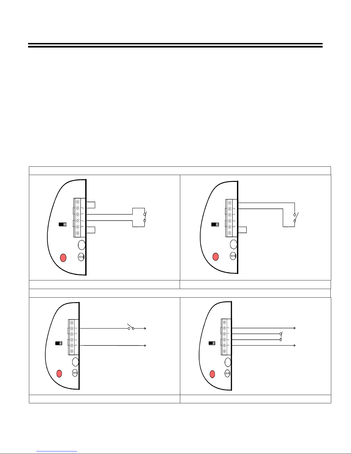
FAI Input Connection Methods
1.
Relay contact transfer using internal voltage
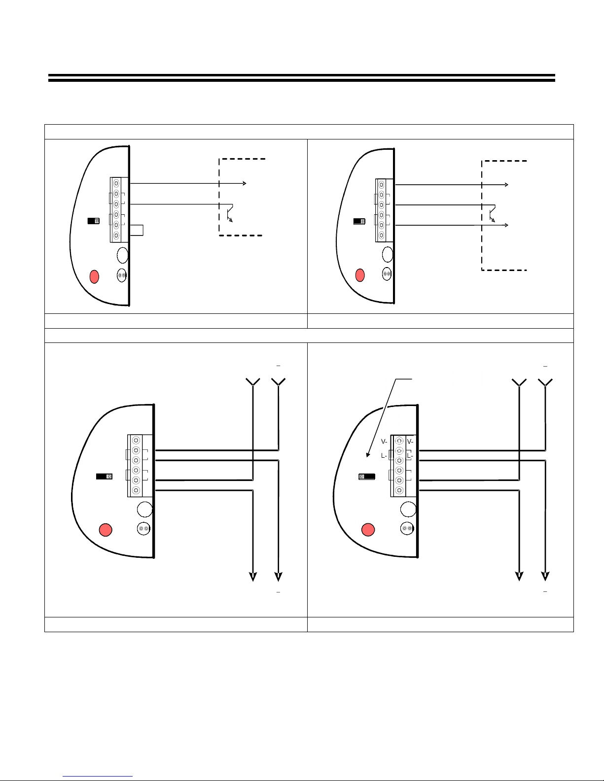
3.
Open collector connection:
FAI ACTIVATES ON CLOSE
2.8.2012
APPENDIX A, PAGE 1
FAI Input Connection Methods
The Beacon FAI input is the most flexible we have yet seen in the industry. It may be activated
by any common means found in the access and fire industry.
When activated, this input will disable the Beacon DC2 output and enable the DC3 output.
The MB8 and CMB8 accessory boards will follow the Beacon FAI input.
Methods of activation include:
source:
a. Normally closed.
b. Normally open.
2. Power from external voltage source:
a. Switched positive.
b. Switched negative.
Relay contact using internal voltage source
FAI
FAI
INPUT
JP3
JUMPER
V-
V-
L-
L-
L+
L+
ED
V+
V+
JUMPER
TB3
REV
BAT
FAI ACTIVATES ON OPEN
a. Internal voltage source
b. External voltage.
4. Direct to NAC loop:
a. DC polarity reversal
b. DC polarity reversal with horn/strobe
synchronization
V-
V-
L-
L-
L+
L+
ED
V+
V+
JUMPER
TB3
REV
BAT
FAI
FAI
INPUT
JP3
Normally closed Normally open
FAI ACTIVATES ON CLOSE
FAI
FAI
INPUT
JP3
V-
V-
L-
L-
L+
L+
ED
V+
V+
TB3
REV
BAT
Normally open Normally closed
AlarmSaf 65A Industrial Way, Wilmington, MA 01887 978 658 6717 www.alarmsaf.com
Power from External voltage source
V-
EXTERNAL PWR -
EXTERNAL PWR +
FAI
FAI
INPUT
JP3
L-
L+
ED
V+
REV
BAT
VL-
L+
V+
TB3
FAI ACTIVATES ON OPEN
EXTERNAL PWR -
EXTERNAL PWR +
52-296 Rev B05
Page 22 of 27
FAI Input Connection Methods
EXTERNAL POWER -
FROM NAC LOOP
TO NAC LOOP
FROM NAC LOOP
TO NAC LOOP
2.8.2012
APPENDIX A, PAGE 2
FAI Input Connection Methods (continued)
"Open collector" connection
V-
V-
L-
L-
OPEN
L+
L+
ED
V+
V+
TB3
REV
BAT
COLLECTOR
Internal source External source
NAC connection
FAI
FAI
INPUT
JP3
FAI
FAI
INPUT
JP3
V-
V-
L-
L-
L+
L+
ED
V+
V+
TB3
REV
BAT
EXTERNAL POWER -
OPEN
COLLECTOR
EXTERNAL POWER +
V-
V-
L-
L+
V+
REV
BAT
L-
L+
V+
TB3
FAI
FAI
INPUT
JP3
ED
NAC LOOP POLARITEIS SHOWN IN THE
ALARM CONDITION
DC polarity reversal DC polarity reversal with sync
+
+
NOTE FAI JUMPER
LOCATION
V-
V-
L-
L+
V+
REV
BAT
L-
L+
V+
TB3
FAI
FAI
INPUT
JP3
ED
NAC LOOP POLARITEIS SHOWN IN THE
+
ALARM CONDITION
+
AlarmSaf 65A Industrial Way, Wilmington, MA 01887 978 658 6717 www.alarmsaf.com
52-296 Rev B05
Page 23 of 27

ABC Buss General Information
2.8.2012
APPENDIX B, PAGE 1
About the Accessory Board Connector
The AlarmSaf Accessory Board Connector (ABC) allows plug-in system expansion using
compatible AlarmSaf accessory boards. The ABC is capable of carrying both primary and
secondary voltages (if applicable), DC common, fault status, and fire alarm interface status.
Products can be daisy-chained together, maintaining voltage, fault, FAI, and DC common
continuity throughout the chain.
NOTE: There are 6-pin and 8-pin versions of the ABC. The 6-pin version carries ONLY a single
voltage while the 8-pin version can carry two independent voltages for dual voltage systems.
CAUTION: The ABC-01 and ABC-02 cables are used on the older Beacon Power supply boards
(PCB#: 38-118 REV A02 or earlier) that have a 6-pin ABC connector.
cables on newer Beacon Power supply boards (PCB # 38-118 REV A03A or later) that have an
8-pin ABC connector or damage to the system could occur.
AlarmSaf 65A Industrial Way, Wilmington, MA 01887 978 658 6717 www.alarmsaf.com
6-Pin and 8-Pin Accessory Board Connectors
DO NOT USE
these
52-296 Rev B05
Page 24 of 27

ABC Buss General Information
2.8.2012
APPENDIX B, PAGE 2
About the Accessory Board Connector (continued)
Voltage Busses (B1 and B2)
The voltage busses (B1 and B2) are carried on pins 5-8 of the ABC. B1 is the primary voltage,
and should typically be the higher of the two voltages in a dual voltage system. The B1 and B2
(if used) voltages are distributed through the accessory boards connected to the ABC. See the
documentation for the particular accessory boards being used for details on how to utilize the
B1 and/or B2 voltages. Note that 6-pin ABC connectors can carry only the B1 voltage, while 8pin ABC connectors can carry both B1 and B2. In order for the B2 voltage to be present, a
second power supply must be included in the system (AC to DC or DC to DC).
CAUTION: If more than one power supply is connected to any of the voltage busses, the
system will not operate properly and damage to the system could occur. Verify that only one
power supply is connected to each voltage buss before powering the system.
Fault Status Buss
The fault status buss carries the DC Fault status between accessory boards and power supplies.
Any product with fault detection and/or reporting capability can report a fault to or from the
ABC chain. Unless otherwise noted in a product’s documentation, AC faults are not transmitted
through the fault status buss.
Some accessory boards have a jumper to split the fault buss. This allows the separation of
faults between two power supplies in some dual voltage systems. If the buss is not split, any
fault on either power supply or any accessory board will show on both power supplies. If the
buss is split, faults on each side of the jumper will go to their respective power supply only,
allowing easier troubleshooting fault conditions, but requiring monitoring of the fault outputs of
both power supplies. Note that only one split should be used in the fault status buss. See the
documentation for the accessory boards in the system to determine which, if any, have a fault
buss split jumper.
NOTE: Not all accessory boards have fault detection or reporting capability; however the fault
status is still carried through these accessory boards to maintain continuity through the chain.
AlarmSaf 65A Industrial Way, Wilmington, MA 01887 978 658 6717 www.alarmsaf.com
52-296 Rev B05
Page 25 of 27

ABC Buss General Information
2.8.2012
APPENDIX B, PAGE 3
About the Accessory Board Connector (continued)
Fire Alarm Interface (FAI) Status Buss
The FAI status buss carries FAI activation signals on systems utilizing a Fire Alarm Interface.
This buss is used to control outputs on compatible accessory boards. See the documentation
for the accessory boards in the system to determine FAI capability.
Some accessory boards have a jumper to split the FAI buss, allowing independent control of
groups of accessory boards and power supplies with multiple FAI input sources. If the buss is
not split, all power supplies and accessory boards with FAI capability will change state upon
activation of
input source will only activate accessory boards or power supplies up to the split. Products
after the split require their own FAI input source.
Note: Not all accessory boards have FAI capability; however the FAI status is still carried
through these accessory boards to maintain continuity through the chain.
any
FAI input source in the chain. If the buss is split, FAI activation of any FAI
DC Common
The DC Common (ground) for the system is maintained through the entire ABC chain. Any
power supplies or accessory boards connected to the chain are common grounded through the
ABC.
Accessory Boards
ACCESSORY MODULE
MODULE DESCRIPTION
ORDER MODEL# ORDER MODEL#
10041, 10042 PD8(F) 8 outputs 00521 ABC-03
10067, 10068 MB8(F) 8 outputs w/FAI & voltage selection 00521 ABC-03
10069, 10070 CMB8(F) 8 outputs w/FAI; 4 Relay Controlled 00521 ABC-03
10066 SPS4 Secondary Power Source Module: 5-18V @ 4A 00523 ABC-05
03207 FAIM Fire Alarm Input Module (used w/PS5-M) 00521 ABC-03
97471 EDB-10 Power Distribution Module for proprietary systems 00523 ABC-05
97472 LDB-8 Power Distribution Module for proprietary systems 00523 ABC-05
ABC CABLE
AlarmSaf 65A Industrial Way, Wilmington, MA 01887 978 658 6717 www.alarmsaf.com
52-296 Rev B05
Page 26 of 27

Glossary
2.8.2012
Glossary
ABC See “Accessory Board Connector”
Accessory Board Connector Connector present on some AlarmSaf power supplies and accessory boards, allowing
plug-in expansion of the system
Accessory Board An AlarmSaf product for use with AlarmSaf power supplies containing an ABC connector.
These boards allow plug-in expansion of the functionality of the system. Examples of
accessory boards include, but are not limited to, voltage distribution (simple and
controlled), secondary DC-DC power supplies, and NAC Circuit expanders.
AC-DC Converter A DC power supply whose voltage input is either direct from the AC line or though a
step-down AC transformer
Buss 1 (B1) The primary DC voltage in a system. Typically the higher of the two voltages in dual
voltage systems
Buss 2 (B2) The secondary DC voltage in a system. Only dual voltage systems use this voltage.
Class 2 Power Limited A voltage output or wiring which conforms to NEC Article 725.
Controlled Distribution Voltage distribution providing on/off control for the outputs. Control can be from FAI, an
access control panel, card reader, or other device. The MB8(F) and CMB8(F) accessory
boards, and the APD8(F) are examples of controlled distribution.
DC-DC Converter A DC power supply whose voltage input comes from another DC source. DC-DC
converters allow multi-voltage system backup with a single battery set.
FAI See “Fire Alarm Interface”
Fire Alarm Interface Input present on some AlarmSaf products allowing control of output(s) in the system.
Typically used for dropping power to mag locks on egress doors during a fire alarm
condition, but can also be used for other control functions, such as resetting smoke
detectors
Negative Trip An input which is activated upon the switching of a DC Common to its terminals. The DC
Common may either be from an external (common grounded) source, or may be
provided as one of the terminals of the input, depending on the product. This input type
is used with a dry contact or open collector input.
Positive Trip An input which is activated upon the switching of a positive DC voltage to its terminals.
The positive voltage may either be from an external (common grounded) source, or may
be provided as one of the terminals of the input, depending on the product. This input
type is used with a dry contact or voltage input.
Power Limited A voltage output or wiring which conforms to NEC Article 725.
PTC A resettable overcurrent protection device, similar to a fuse or circuit breaker.
Rack Mount A product which has an enclosure that allows mounting in a standard 19 inch equipment
rack
Simple Distribution Voltage distribution without any control function for the distributed outputs. Power is
always available to the outputs. The PD8(F) accessory board is an example of simple
distribution.
Voltage Distribution Splitting a bulk power supply output into multiple, current limited outputs to prevent a
single circuit failure from talking down an entire system. The multiple terminal outputs
also simplify wiring by providing a pair of terminals for each circuit, rather than wiring
several circuits to a single pair of terminals.
AlarmSaf 65A Industrial Way, Wilmington, MA 01887 978 658 6717 www.alarmsaf.com
52-296 Rev B05
Page 27 of 27

Compatible Fire Device List
The following Fire devices have been determined to be compatible with the AlarmSaf Beacon Line of power
supplies. Access Control devices used must be verified for a compatible voltage range.
Page 1 of 1 Document 52-325 Rev A.01 9/27/05
Beacon Power Supply Installation Instructions - Addendum A
17-3124Door HolderSDH-8DSiemens
17-3124Door HolderSDH-7DSiemens
17-3124Door HolderSDH-6DSiemens
17-3124Door HolderSDH-5DSiemens
17-3124Door HolderSDH-4DSiemens
17-3124Door HolderSDH-3DSiemens
17-3124Door HolderSDH-2DSiemens
20-29244-Wire Duct SmokeDH100ACDCFire-Lite
20-29244-Wire Smoke2424THFire-Lite
20-29244-Wire Smoke2424ATFire-Lite
20-29244-Wire Smoke2424AITFire-Lite
20-29244-Wire Smoke2424Fire-Lite
Voltage Range
(VDC)
Nominal Voltage
(VDC)Device TypeModelManufacturer
AlarmSaf
65A Industrial Way, Wilmington, MA 01887-3499, USA, Voice 978-658-6717, Fax:978-658-8638, www.alarmsaf.com

P2
38119 Rev B
PD8 PD8F
3A
UTILISER UN FUSIBLE DE RECHANGE DE MEME
32V
SAME TYPE AN D RA T IN GREPLACE FUSES ONLY WITH
B2B1
AlarmSaf c 2005
P1
B2
F8F7F6F5F4F3F2F1
B2
B1
R1
+OUT1- +OUT2- +OUT3- +OUT4-
TB1
+OUT1- +OUT2- +OUT3- +OUT4-
B1
FAI
FLT
RET
D2
JP1
DC
D1
+OUT5-
+OUT5-
+OUT6-
+OUT6-
+OUT7-
+OUT7-
+OUT8-
+OUT8-
TB2
Model PD8(F)
Basic Power Distribution Board
Operating and Installation Instructions
52-326 Rev B.01

PD8(F) Installation Instructions
10/27/2006, 1:58:40 PM
Table of Contents
Section Page
1 Introduction 3
2 Applicable Standards / Documents 4
3 System Overview 5
3.1 Electrical Ratings and Specifications 5
3.2 PD8(F) Terminal and Connector Descriptions and Electrical Ratings 6
3.3 ABC Connectors and Harnesses 7
3.4 Output Terminals 8
4 Installation 9
4.1 Mounting 9
4.2 Wiring 10
5 Operating the PD8(F) 11
5.1 Jumper Configuration 11
5.2 Visual Indicators 12
5.3 Troubleshooting 12
6 Specifications 13
6.1 Electrical Specifications 13
6.2 Temperature Specifications 13
6.3 Mechanical Specifications 13
Appendix A - Sample Applications 14
A.1 14
AlarmSaf 65A Industrial Way, Wilmington, MA 01887 978 658 6717 www.alarmsaf.com
52-326 Rev B.01
Page 2 of 14

PD8(F) Installation Instructions
10/27/2006, 1:58:40 PM
Section 1
Introduction
The PD8(F) Basic Power Distribution board provides eight outputs to any AlarmSaf
power supply or accessory board with an ABC expansion port. It accepts inputs from
one or two independent voltage sources, either of which is available to ALL outputs by
jumper selection.
y Eight individually protected outputs
y Output voltage able to be selected (as a group) from one of two voltage busses
y Available with Class-2 Power Limited outputs (PD8) or Fused (non-power limited)
outputs (PD8F)
y Each output is capable of supplying up to 3A (PD8F) or 1.6A (PD8) up to the
maximum current capability of each voltage source
y Fused versions use easily obtainable ATM-3 automotive miniature blade fuses
AlarmSaf 65A Industrial Way, Wilmington, MA 01887 978 658 6717 www.alarmsaf.com
52-326 Rev B.01
Page 3 of 14

PD8(F) Installation Instructions
10/27/2006, 1:58:40 PM
Section 2
Applicable Standards / Documents
NFPA Standards
NFPA 72 National Fire Alarm Code
NFPA 70 National Electrical Code
NFPA 731 Standard for the Installation of Electronic Premises Security Systems
US Standards
UL 294 Access Control System Units
UL 1481 Power Supplies for Fire Protective Signaling System
UL 1076 Proprietary Burglar Alarm Units and Systems
UL 2044 Commercal Closed-Circuit Television Equipment
Canadian Standards
ULC S527 Standard for Control Units for Fire Alarm Systems
ULC S318 Standard for Power Supplies for Burglar Alarm Systems
CAN/CSA-C22.2 No. 107.1-01 General Use Power Supplies
Other
Applicable Local and State Building Codes
Requirements of the Local Authority Having Jurisdiction (LAHJ)
AlarmSaf 65A Industrial Way, Wilmington, MA 01887 978 658 6717 www.alarmsaf.com
52-326 Rev B.01
Page 4 of 14

PD8(F) Installation Instructions
10/27/2006, 1:58:40 PM
Section 3
System Overview
3.1 Electrical Ratings and Specifications
Manufactured By
AlarmSaf
65A Industrial Way
Wilmington, MA 01887
Tel: 978 658 6717
800 987 1050
www.alarmsaf.com
Model Numbers
PD8, PD8F
Electrical Ratings
Two Inputs: 0 to 24VDC Nominal @ 14 Amps maximum per inputInputs
Outputs
Eight Outputs: 1.6A (PD8) or 3A (PD8F) per output up to the
maximum capability of the base power supply selected. Output
voltage determined by base power supply selected.
ATM-3 Automotive Miniature Blade-typeFuse Type (PD8F only)
Product Use
When installed in accordance with all standards listed in Section 2 of this document
and used with an appropriate listed supply, the PD8(F) provides eight constant outputs,
sourced from one of two voltage sources for powering devices such as (but not limited
to) Mag Locks, Door Strikes, Card Readers, Smoke Dampers, 4-Wire Smoke detectors,
etc.
AlarmSaf 65A Industrial Way, Wilmington, MA 01887 978 658 6717 www.alarmsaf.com
52-326 Rev B.01
Page 5 of 14

PD8(F) Installation Instructions
10/27/2006, 1:58:40 PM
3.2 PD8(F) Terminal and Connector Descriptions and Electrical Ratings
RatingDescriptionTerminal / Connector
ABC Input or OutputP1
ABC Input or OutputP2
TB1 - Outputs 1 through 4
Output 1 +Out1 +
Output 1 -Out1 -
Output 2 +Out2 +
Output 2 -Out2 -
Output 3 +Out3 +
Output 3 -Out3 -
Output 4 +Out4 +
Output 4 -Out4 -
TB2 - Outputs 5 through 8
Output 5 +Out5 +
Output 5 -Out5 -
Output 6 +Out6 +
Output 6 -Out6 -
Output 7 +Out7 +
Output 7 -Out7 -
Output 8 +Out8 +
Output 8 -Out8 -
0-24V Nominal at 14A per Buss (controlled by
base supply selected)
1.6A (PD8) or 3A (PD8F) maximum - Voltage
determined by base supplies and jumper selection
1.6A (PD8) or 3A (PD8F) maximum - Voltage
determined by base supplies and jumper selection
1.6A (PD8) or 3A (PD8F) maximum - Voltage
determined by base supplies and jumper selection
1.6A (PD8) or 3A (PD8F) maximum - Voltage
determined by base supplies and jumper selection
1.6A (PD8) or 3A (PD8F) maximum - Voltage
determined by base supplies and jumper selection
1.6A (PD8) or 3A (PD8F) maximum - Voltage
determined by base supplies and jumper selection
1.6A (PD8) or 3A (PD8F) maximum - Voltage
determined by base supplies and jumper selection
1.6A (PD8) or 3A (PD8F) maximum - Voltage
determined by base supplies and jumper selection
P2
PD8 PD8F
+OUT1- +OUT2- +OUT3- +OUT4-
TB1
+OUT1- +OUT2- +OUT3- +OUT4-
+OUT5-
+OUT5-
Figure 3.2.1
AlarmSaf c 2005
+OUT6-
+OUT6-
+OUT7-
+OUT7-
+OUT8-
+OUT8-
P1
B2
B2
B1
B1
FAI
FLT
RET
TB2
AlarmSaf 65A Industrial Way, Wilmington, MA 01887 978 658 6717 www.alarmsaf.com
52-326 Rev B.01
Page 6 of 14

PD8(F) Installation Instructions
10/27/2006, 1:58:40 PM
3.3 ABC Connectors and Harnesses
3.3.1 The ABC buss supplies the voltages (B1 and B2) and FAI control to compatible
accessory boards. B1 is supplied through pins 5 and 6 while B2, if used, is supplied
through pins 7 and 8 of each connector. By using the appropriate cables, one or two
independent voltage sources can be connected to the PD8(F) for distribution to it’s
outputs.
3.3.2 Single Voltage Distribution
A single power source can be connected to the PD8(F) by using a white 6-6 cable
(AS Part Number A099052) connected to pins 1 through 6 of one of the ABC
connectors (P1 or P2).
3.3.3 Dual Voltage Distribution
3.3.3.1 If both source voltages are present on the ABC buss, use a brown 8-8 cable
(AS Part Number A099068 or A099069) connected to either ABC Connector to
provide both B1 and B2.
3.3.3.2 If two independent supplies are used, a white 6-6 cable is needed for B1
on either ABC connector, and a red 6-8 cable is needed for B2 on the other ABC
connector.
3.3.4 Cable Types
DescriptionLengthColorAS PNCable Type
ABC-018 inchesWhiteA0990526-6
ABC-0218 inchesWhiteA0990636-6
ABC-038 inchesBrownA0990688-8
ABC-0418 inchesBrownA0990698-8
ABC-058 inchesRedA0990706-8
ABC-0618 inchesRedA0990716-8
ABC-01 Used to connect a Beacon power supply to the first accessory board, when
the ABC slot is used or accessory board is located close to power supply.
ABC-02 Used to connect a Beacon power supply to the first accessory board, when
the ABC slot is used or accessory board is not located close to power supply.
ABC-03 Used to connect accessory board to accessory board over short distances.
ABC-04 Used to connect accessory board to accessory board over long distances.
ABC-05 Short cable used to connect two Beacons to single accessory board for high
power dual voltage systems.
ABC-06 Long cable used to connect two Beacons to single accessory board for high
power dual voltage systems.
AlarmSaf 65A Industrial Way, Wilmington, MA 01887 978 658 6717 www.alarmsaf.com
52-326 Rev B.01
Page 7 of 14

PD8(F) Installation Instructions
10/27/2006, 1:58:40 PM
3.4 Output Terminals
The PD8(F)’s output terminals (TB1 and TB2) provide power distributed from the B1 or
B2 (if present) supplies. The voltage source selection is made through the voltage buss
jumper (JP1) setting. See Section 5 for configuration jumper settings.
Each output is protected by either an ATM-3 fuse (PD8F) or a 1.6A PTC (PD8). If an
output PTC is tripped, remove the output load for 30 seconds.
Caution - Observe the polarity of the PD8(F) output terminals with respect to the load
or damage to the load may occur.
+OUT1- +OUT2- +OUT3- +OUT4-
TB1
+OUT1- +OUT2- +OUT3- +OUT4-
+OUT5-
+OUT5-
Figure 3.4.1
+OUT6-
+OUT6-
+OUT7-
+OUT7-
+OUT8-
+OUT8-
TB2
AlarmSaf 65A Industrial Way, Wilmington, MA 01887 978 658 6717 www.alarmsaf.com
52-326 Rev B.01
Page 8 of 14
PD8(F) Installation Instructions
10/27/2006, 1:58:40 PM
Section 4
Installation
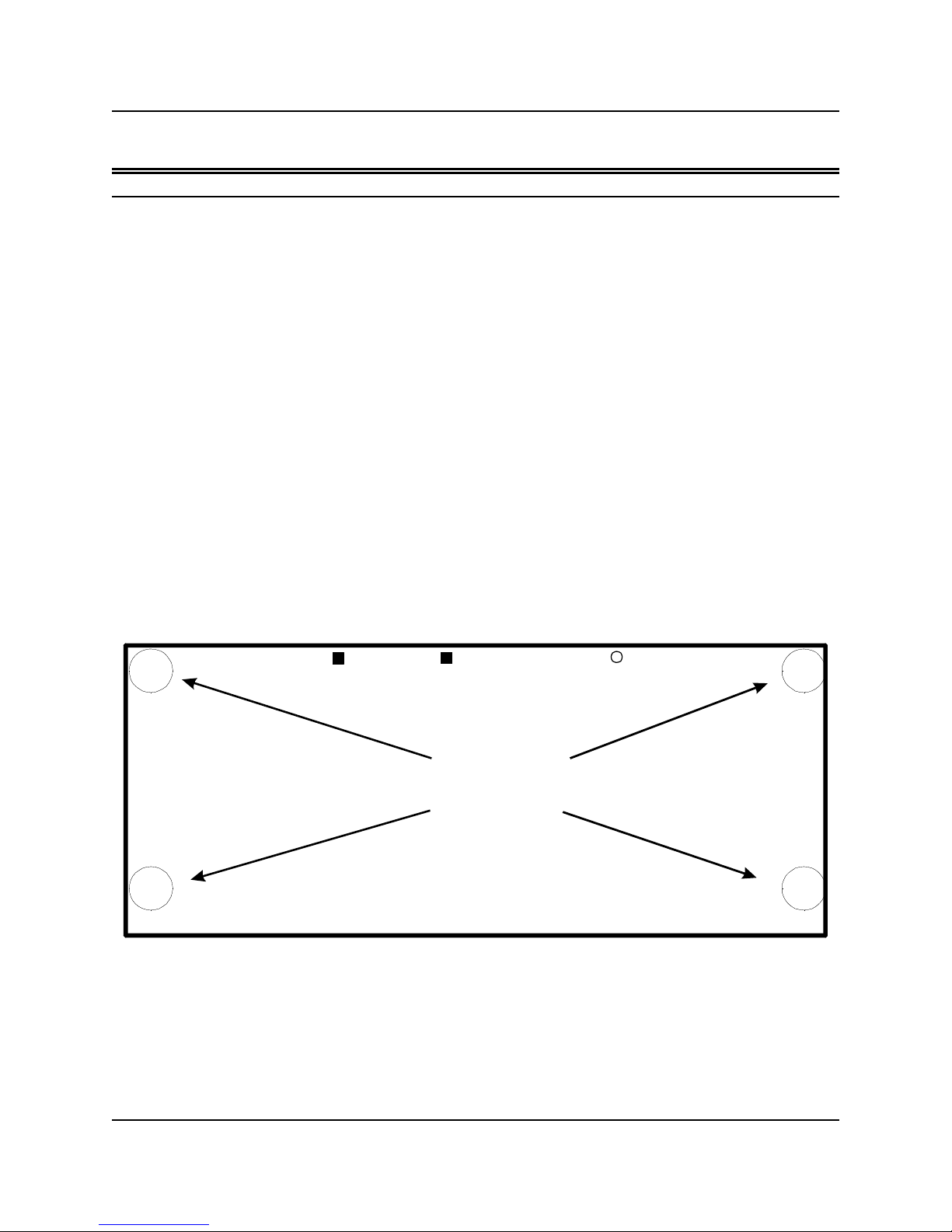
4.1 Mounting
The PD8(F) mounts either in the accessory board space on the power supply or to the
back of a metal enclosure.
4.1.1 Mounting On a Power Supply
1. Remove and save the four mounting screws from the accessory board mounting
space on the power supply.
2. Install 6-32 x 1 1/4” Male-Female standoffs in the four locations where the
screws were removed (the aluminum standoff, if present, is installed in the top
left mounting hole).
3. Mount the PD8(F) to the standoffs using the screws removed in step 1
4. Connect ABC cable(s) appropriately (See section 3.3)
4.1.2 Mounting In a Metal Enclosure
1. Install four 6-32 x 3/4” Female-Female nylon standoffs on the appropriate
mounting studs in the enclosure (the aluminum standoff, if present, is installed
on the top left mounting stud).
2. Mount the PD8(F) to the standoffs using 6-32 x 3/8” screws.
3. Connect ABC cable(s) appropriately (See section 3.3)
PD8 PD8F
MOUNTING
HOLES
Fig 4.1.1
AlarmSaf c 2005
AlarmSaf 65A Industrial Way, Wilmington, MA 01887 978 658 6717 www.alarmsaf.com
52-326 Rev B.01
Page 9 of 14

PD8(F) Installation Instructions
10/27/2006, 1:58:40 PM
4.2 Wiring
4.2.1 Wire Routing
All wiring must be installed in accordance with NFPA70 [NEC760], NFPA72, and all
local code requirements.
Power Limited wiring requires that power limited and non-power limited wiring
remain physically separated. Any power limited circuit entering the enclosure must
remain at least one quarter inch (¼”) away from any non-power limited circuit
wiring. Any power limited circuit wiring must enter and exit the enclosure through
different knockouts than non-power limited circuit wiring.
Wiring within the enclosure should be routed around the perimeter of the cabinet.
It should not be routed across the circuit boards. See the enclosure’s
documentation for complete wire routing instructions.
4.2.2 ABC Connector
See section 3.3
4.2.3 Output Wiring
Locate the output wiring terminal blocks (TB1 and TB2) and remove the terminal
block from the header. Connect the wiring for the equipment to be powered to
the terminal block. The PC board is labeled with the output numbers and polarity
(See also section 3.2). Replace the terminal block on the header.
NOTE: Wire size for these terminals must be 22-14 AWG.
4.3 Labeling
If the PD8(F) was purchased separately from the power supply unit, the supplied
label must be applied to the inside cover of the power supply’s enclosure. The label
shall not cover any ventilation holes or other labeling on the enclosure.
AlarmSaf 65A Industrial Way, Wilmington, MA 01887 978 658 6717 www.alarmsaf.com
52-326 Rev B.01
Page 10 of 14

PD8(F) Installation Instructions
10/27/2006, 1:58:40 PM
Section 5
Operating the PD8(F)
5.1 Jumper Configuration
Before powering a system containing a PD8(F), the jumper must be set for proper
operation. Failure to do so before applying power could damage the system.
Factory
Default
Left (B1)
JP1
Voltage Buss
Selection
SettingsDescriptionJumper
Left (B1) - The PD8(F)’s outputs are supplied from B1
Right (B2) - The PD8(F)’s outputs are supplied from B2
5.1.1 The Voltage Buss Selection jumper (JP1) is used to select which of the two
voltage busses on the ABC connector(s) are to be used to supply the outputs. The
jumper selects the source for ALL EIGHT outputs. If individual selection is required,
use the MB8(F).
B2B1
JP1
D2
+OUT3- +OUT4-
+OUT3- +OUT4-
DC
+OUT5-
+OUT5-
+OUT6-
+OUT6-
Figure 5.1.1
AlarmSaf 65A Industrial Way, Wilmington, MA 01887 978 658 6717 www.alarmsaf.com
52-326 Rev B.01
Page 11 of 14

PD8(F) Installation Instructions
10/27/2006, 1:58:40 PM
5.2 Visual Indicators
The PD8(F) has one LED to indicate status of the input voltage selected for the outputs.
The LED lights when there is voltage available to the outputs.
B2B1
JP1
D2
5.3 Troubleshooting
No voltage on output
Incorrect voltage on output
LED not lit
+OUT3- +OUT4-
+OUT3- +OUT4-
DC
+OUT5-
+OUT5-
+OUT6-
+OUT6-
Figure 5.2.1
Blown output fuse (PD8F)
Tripped output PTC (PD8)
Power supply outputting
incorrect voltage
No voltage on the voltage buss
selected
Jumper set improperly
Jumper missing
SolutionPossible CauseCondition
Verify proper jumper settingJumper setting incorrect
Verify jumper presentMissing jumper
Verify the power supplyNo voltage supply
Check output wiring and
replace fuse
Check output wiring and
remove load for 30 seconds to
reset
Verify proper jumper settingIncorrect voltage buss selected
Check power supply
Check the selected power
supply and ABC cable
Verify proper setting of jumper
JP1
Verify jumper JP1 is present and
set properly
AlarmSaf 65A Industrial Way, Wilmington, MA 01887 978 658 6717 www.alarmsaf.com
52-326 Rev B.01
Page 12 of 14

PD8(F) Installation Instructions
10/27/2006, 1:58:40 PM
Section 6
Specifications
6.1 Electrical Specifications
6.1.1 Input Voltage (B1 and B2) 0-24VDC Nominal
6.1.2 Input Current (B1 and B2) 14A maximum per buss
6.1.3 Battery Requirement The PD8(F) draws 0.01A in
6.2 Temperature Specifications
6.2.1 Ambient Temperature Range 0ºC to 49ºC (32ºF to 120ºF)
6.2.2 Ambient Humidity 93% at 32ºC (90ºF) Maximum
6.3 Mechanical Specifications
6.3.1 Weight 0.05 Lbs (Not including hardware
6.3.2 Size 4.85”L x 2.10”W x 1.00”H
6.3.3 CAD Drawing
addition to the output load
or cables)
Note: Width includes terminal
block overhang of 0.2”
2.00"
P2
38119 Rev B
32V
+OUT1- +OUT2- +OUT3- +OUT4-
TB1
+OUT1- +OUT2- +OUT3- +OUT4-
PD8 PD8F
3A
UTILISER UN FUSIBLE DE RECHANGE DE MEME
R1
4.8"
SAME TYPE AND RATINGREPLACE FUSES ONLY WITH
B2B1
JP1
D2
DC
+OUT5-
+OUT5-
4.5"
Figure 6.3.1
D1
AlarmSaf c 2005
+OUT6-
+OUT7-
+OUT6-
+OUT7-
F8F7F6F5F4F3F2F1
+OUT8-
+OUT8-
TB2
P1
B2
B2
B1
B1
FAI
FLT
RET
1.5"
AlarmSaf 65A Industrial Way, Wilmington, MA 01887 978 658 6717 www.alarmsaf.com
52-326 Rev B.01
Page 13 of 14

PD8(F) Installation Instructions
10/27/2006, 1:58:40 PM
Appendix A
Sample Applications
A.1 Single Voltage Power Management With The PD8(F)
BN1
SET FOR 12 OR 24V
AC Connect
AC Power
Trouble
Reporting
PD8-1
PD8
Accessory Board
SysFlt Com
SysFlt NC
SysFlt NO
ACFlt NO
ACFlt NC
Out1+
Out1-
Out2+
Out2-
Out3+
Out3-
ACFlt Com
P1
Out4+
Out4-
Out5+
Out5-
Out6+
Out6-
Out7+
Out7-
Out8+
Out8-
AS DESIRED
24V
12V
ABC Connector (P2)
4
12V Battery
Battery Set
12 or 24V BASED ON BN SETTING
Batt-
Batt+
Neg 2
FAI V-
FAI L- In
FAI L- Out
FAI L+ Out
FAI L+ In
FAI V+
DC1-
DC1+
DC2-
DC2+
DC3-
DC3+
2
1
3
Pos 1
Pos 2
Neg 1
12V Battery
12 or 24V POWER
FOR AUXILIARY
EQUIPMENT
12 or 24V LOCK
POWER TO DOOR
CONTROL RELAYS
MAG1
2
2
1
-
-
+
+
MAG2
+
REX PIR3
1
-
-
+
REX PIR4
The BN power supply is configured to provide either 12 or 24 VDC to one PD8(F) power
distribution module.
The PD8(F) will split the 12 or 24VDC into eight individually protected outputs for use in
powering locks, doorstrikes, or auxiliary equipment such as REX PIRs, keypads, egress
timers, or readers.
The diagram illustrates a common eight door system with two maglocks used for the
egress doors, six doorstrikes used for internal access control and a mix of auxiliary
power needs such as cameras, keypads, and REX PIRs. Emergency access buttons
should be used on the maglocks due to FAI not being used.
The PD8 should be used for Class 2 power limited service.
The PD8F should be used if fuse protection is desired.
A single battery set is used to provide standby power to both the locks and the control
equipment.
All components as shown will fit within a B02 (12"H X 12"W X 4"D) enclosure , while
allowing space for a 12V - 14 Ah or 24V - 7Ah standby battery set.
AlarmSaf 65A Industrial Way, Wilmington, MA 01887 978 658 6717 www.alarmsaf.com
52-326 Rev B.01
Page 14 of 14
 Loading...