

Alarm RR-PM1200PAK User Manual

RR-PM1200PAK
ALARM LOCK
345 Bayview Avenue
Amityville, New York 11701
For Sales and Repairs, (800) 645-9445
For Technical Service, (800) 645-9440
© ALARM LOCK 2000
GENERAL DESCRIPTION
The Alarm Lock Remote Release PowerMag is an innovative 1200 lb. electromagnetic locking system with infrared
remote control(s). The Alarm Lock System (model RRPM1200PAK) offers the security of a mag and the convenience of
pocket-size infrared keyfobs for management, staff or receptionists--up to 100 individual remote controls (part no.
AL-REMOTE) are supported! These lithium-battery powered remote controls can release the mag from either side of the
door and feature easy single button operation.
INSTALLATION & PROGRAMMING
INSTRUCTIONS
WI1020 08/00
SYSTEM FEATURES
• Advanced 1200 Lb. Electromagnetic Lock with
Innovative Infrared Remote Release
• The power of a Magnetic Lock with the convenience of
pocket-size remote controls for reception or staff..
• Unique patented feature allow the Power Mag to sense
the door status and provide high end options such as
door chime, door held open alarm, relay output follows
door position, etc..
• Complete RR-PM1200PAK turnkey system includes:
Advanced 1200 Lb. Power Mag, one AL-REMOTE
KeyFob remote control, and plug-in AC transformer.
• Plug-in 12 V AC transformer eliminates the requirement
for running wires or employing an electrician’s services.
• Supports up to 100 individual KeyFobs (model no. AL-
REMOTE).
• KeyFobs release Power Mag from either side of door.
• KeyFobs feature single button operation with positive
“click” response.
• KeyFobs are automatically-enrolled by system in easy
programming mode and each is audibly and visually
confirmed.
• Can optionally be powered by Alarm Lock Regulated
Power Supplies (AL-P1A, AL-P3A, or AL-P6A).
• Programmable remote switch functions.
• All programming stored in non-volatile memory - will not
be lost on loss of power.
• UL Listed; CE
SPECIFICATIONS
Input Power 12 Volt AC Plug In, Class 2 Transformer,
(AC) 8.5 to 20 VA.
Input Power optional 12V, 500 mA DC power supply
(DC) required per Maglock.
1200PM 2.875” x 10.5” x 1.5” / 7.3cm x 26.8cm x 3.8cm
Dimensions: (HxWxD)
AL-REMOTE Protected Side (inside): 35 feet (min.)
Range: Unprotected Side (outside): 10 feet (min)
ORDERING INFORMATION
AL-REMOTE additonal IR KeyFob for PM1200 system.
PM1200 1200lb MagLock (w/o transformer or
AL-REMOTE)
1
Mounting the PM1200 POWER MAG
1 Fold template where indicated to form a 90° angle. For a swinging door place template against door header and door
opposite hinge side of door jamb. For a pair of swinging doors place template against door and door header at center of
door opening. Transfer ARMATURE PLATE MOUNTING hole locations to door. If outside access is required, the “LIGHT
PIPE HOLE” location should also be transferred at this time. DO NOT transfer door frame hole locations to header at this
time.
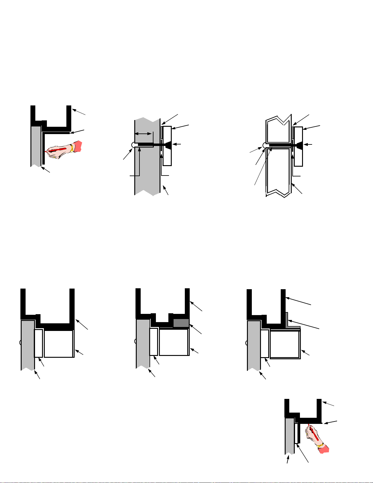
2 Follow template instructions for hole sizes. Use the illustrations below to determine proper armature mounting hole
door
header
template
Solid Door
washers
armature
1 3/8”
5/16” 18 screw
sexnut
1/2”
Drill 11/32“ hole through door. From
sexnut side of door drill 1/2 dia. hole
1 3/8” deep. Mount armature to door
with hardware provided.
rubber washer
door
door spacer
Hollow Steel Door
washers
armature
5/16” 18 screw
sexnut
21/32”
DRILL
Drill 11/32” hole through door. From
sexnut side of door drill 21/32 hole
through only one side of door. Mount
armature to door with hardware provided.
rubber washer
door
3 Note type of door frame header and install filler plate or angle bracket as required to provide a flat surface on the header
over the entire depth of the lock.
Standard
header
lock
armature plate
door
Filler Plate
armature plate
door
Angle Bracket
header
filler plate
lock
armature plate
door
4 Fold template where indicated to form a 90° angle. Place template against the ARMATURE
and the Door Header. Transfer MOUNTING PLATE hole locations to the header.
header
angle bracket
lock
header
template
2
door
armature
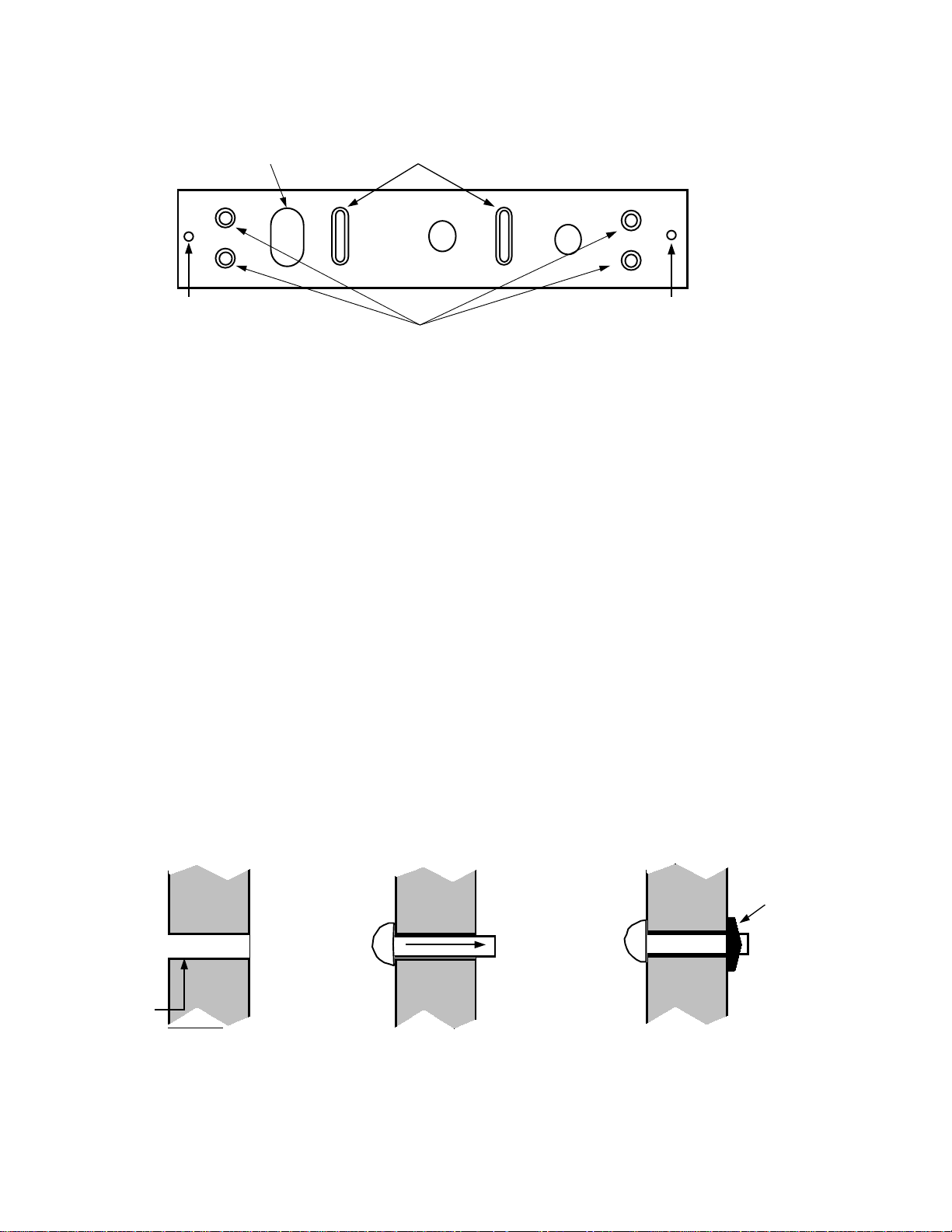
View of Mounting Plate Under the Header
Adjust the plate so that it
forms a right angle with the armature
2
and drill a hole for the wires.
Used for attaching lock
to mounting plate.
Drill and install the remaining mounting screws.
Drill the 2 mounting holes within each slot as indicated on template.
Install flat head screws, tighten to allow adjustment of plate position.
1
Used for attaching lock to
mounting plate.
3
5 Install mounting plate to header by drilling pilot holes at slot locations (see item 1 in above drawing), then secure plate
with 2 flat head screws. These two (2) screws are installed in the slotted holes to allow for adjustment before drilling and
installing the (4) remaining outer screws (item 3 in above drawing).
6 Adjust the mounting plate so that it and the armature plate form a right angle.
7 Using the mounting plate as a template, drill the wire hole and pilot holes for the four (4) outer flat head screw positions.
8 Install the four (4) #10 flathead screws provided.
9 Fasten the lock to mounting plate with the two (2) 1/4-20 socket screws provided. Compensate for any misalignment
by adding or subtracting washers at armature mounting screw.
10 Firmly tighten all screws. Install anti-tamper plugs into holes over each socket head mounting screw. Use soft hammer to
avoid damaging lock case.
11 Rubber on armature screw head must not be trimmed or modified for correct operation.
NOTE: For steel door frame use self tapping flat head screws supplied; for wood door frames use the supplied wood
screws.
Installing the Infrared Light Pipe.
Outside Inside
25/64”
Kepnut
1 Drill 25/64” hole through
door at position marked
“LIGHT PIPE HOLE” on
template.
2 From outside of door
slide light pipe through
hole.
3 Firmly press supplied kepnut
over the shaft of the light
pipe until it is held securely
against door.
3
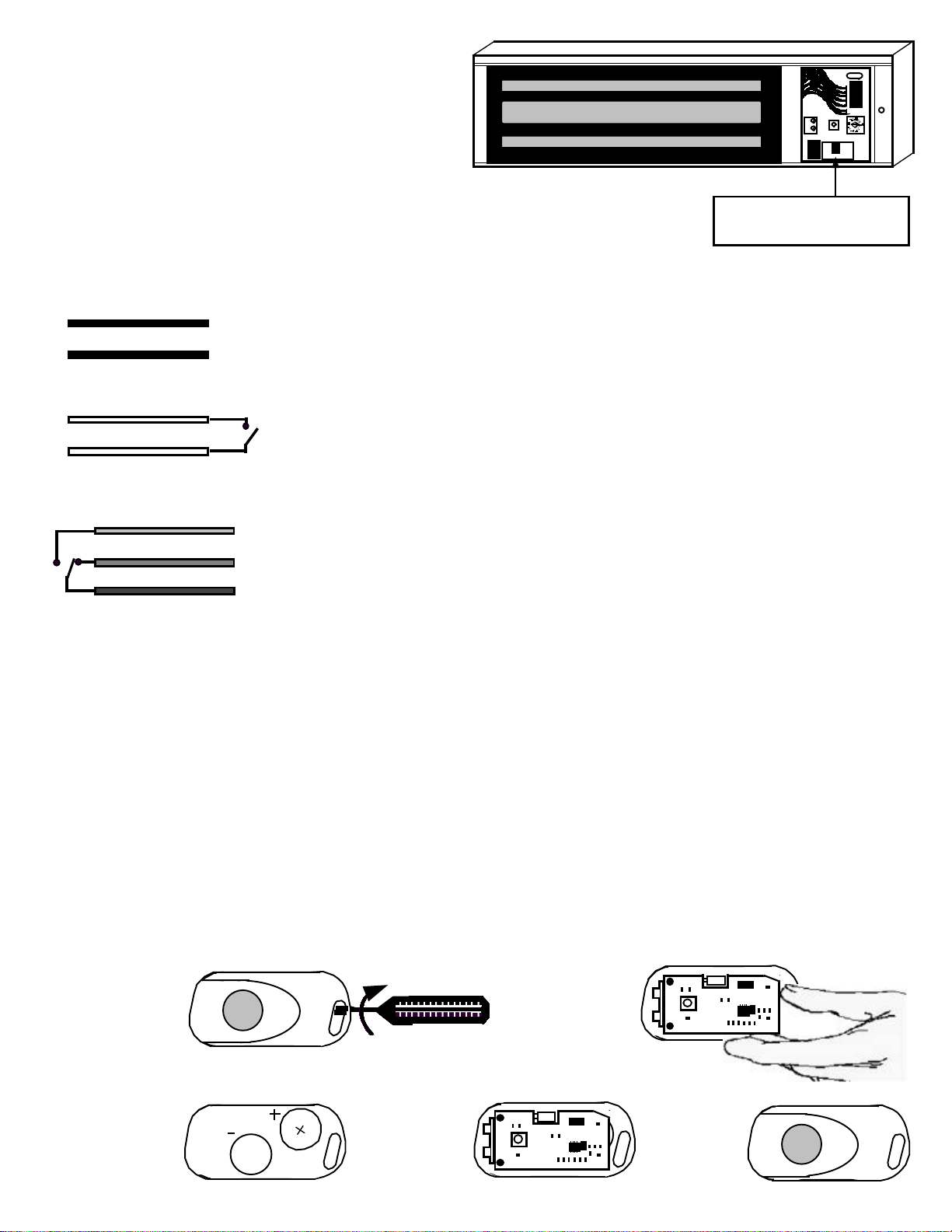
Wiring the PM1200 POWER MAG
1 Open wiring bay cover by removing Phillips head screw.
2 Bring outside wires into wiring bay through wire access
hole at top of bay.
3 Cut wire down to appropriate length and make
connections using supplied wire nuts.
4 Carefully tuck wires back into the wiring bay.
5 Close cover.
Note: Only the Black AC power wires are mandatory connections.
All others are optional.
Insure that wiring does not
block the Infrared sensor.
Power Connections
BLACK
BLACK
Remote Switch Input
WHITE
WHITE
Auxiliary Relay Output
YELLOW
GREEN
BLUE
N/O
N/C
COM
Connect to the supplied 12V AC 10 VA Plug in transformer, or to an optional 12V
DC 500 mA Power supply.(DC input is non polarized)
Connect to a normally open door bell push-button, momentary remote release
push-button or latched passage mode switch. (See Remote Switch Input options in
System Option Programming Commands)
Wire the Auxiliary Relay Output to an optional peripheral device.
(See Auxiliary Relay Output options in System Option Programming Commands)
Relay Contact rated for 12 V DC, 1 Amp Max.
The AL-REMOTE KeyFob
The AL-REMOTE KeyFob is a dual infrared element device which transmits a digitally encoded infrared signal to the Power
Mag. The operational range of the KeyFob is a minimum of 35 feet from the Power Mag. When used from the protected side
of the door (inside), aiming the KeyFob in the general direction of the Power Mag is sufficient. However, if using the supplied
light pipe to allow access from the outside, the KeyFob must be aimed at the light pipe in order to activate the Power Mag.
An indication that the batteries inside the KeyFob are low and must be replaced will be a noticeable decrease in the
effective range of the KeyFob. For example, if the KeyFob range is typically 35 feet and it falls to 20 feet, this is an
indication that the batteries should be replaced.
The KeyFob should not be exposed to extreme temperatures and should not be submersed in water.
Replacing the AL-REMOTE KeyFob batteries
Following is the procedure for replacing the KeyFob batteries. The replacement battery is a Duracell model DL2032. (2
required). Warning: Replace batteries only with the same type as specified above. Use of another battery may present a
risk of fire or explosion. Do not recharge or disassemble battery, or dispose of in fire.
1 Insert flat blade
screwdriver into the
slot between the key
ring loops and gently
twist until the case
pops open.
3 Remove old
batteries. Observing
polarity (+ / -),
insert new batteries.
4
DURACELL
4 Place circuit
board back
into base over
new batteries.
2 Gently lift circuit
board from
KeyFob base to
expose the battery
compartment.
5 Align top
of housing
to base and
snap together.
 Loading...