

Page 1
ADA
Radial Fan Unit Heaters
Operation Manual
Page 2

Revision Date: 210806 Published on: 210806
Revision No: 0
Page 3

ADA
Radial Fan Unit Heaters
Operation Manual
Contents
Introduction .............................................................................5
Guarentee and Service ...........................................................6
General Characteristics ..........................................................7
Dimensions ..............................................................................8
Other Technical Characteristics .............................................8
Air Distribution Distances .....................................................................9
Coil Water Pressure Drop Graphic .......................................................9
Installation Rules ...................................................................10
Location Selection and Mounting .......................................................10
Water Pipes Installation ...................................................................... 11
Electricity ............................................................................................14
Trouble-Shooting Manual .....................................................15
Product Ordering Notation ...................................................15
Page 4

Introduction
First of all, thanks for preferring ALARKO.
This manual includes operation and maintenance information
regarding ALARKO ADA radial fan unit heaters.
Please, carefully read this manual for that you can operate your
heater with high output, cheap, trouble free and long-term
use. In addition to the operation and maintenance information, the
manual includes a summary of advertising and technical data,
installation, commissioning of the heater.
For more detailed information of the heater, you can consult
the product advertising booklet and ALARKO CARRIER
authorized vendors and services.
Keep this manual for further consulting, as required.
Our authorized vendors and services will inform you about the
utilization and maintenance of the heater, after they mount and
operate your unit. You can ask repeatedly the issues that are not
well-understood.
Our experts shall be pleased to answer your questions.
5
Page 5

6
Guarantee and Service
In the terms of obeying the instructions, warnings, points in this
manual and the standards in charge (EN norms and directives
must be applied if mentioned standards are not in use) heater is
under 2 (two) years guarantee. Alarko Carrier is responsible for
repairing or renewing if the following conditions are available.
Guarantee Document must be filled by the franchiser that you have
bought the heater and must be send to Alarko Carrier.
Assembling and installing faults and problems, problems that will
be occured because of wrong upkeeping and working are not under
guarantee. Problems related to lime coating or/and any other materials coating and corrosion on the heat transfer units of the heater
are not under guarantee conditions.
Minimum life of these kind of products is mentioned as 10 (ten)
years by the minister of industry and commerce. Manufacturer and
sales companies are to supply all spare parts and services to the
clients in this period.
The problems happened by the following mentioned issues are out
of guarantee conditions:
- Heater without guarantee document.
- Heater fixed,repaired or adjusted by unauthorized services.
- Heaters with wrong type selection, wrong installing and assembling.
- Heaters used wrong conditions and out of aim.
- Problems occured while transportation, stocking or problem occured under atmospheric conditions.
- The problems occured by physical or chemical effects.
- Wrong installation or connection to water plumbing systems.
- The problems occured by scratching,touching to control and safety
systems of the heater.
Page 6
7
General Characteristics
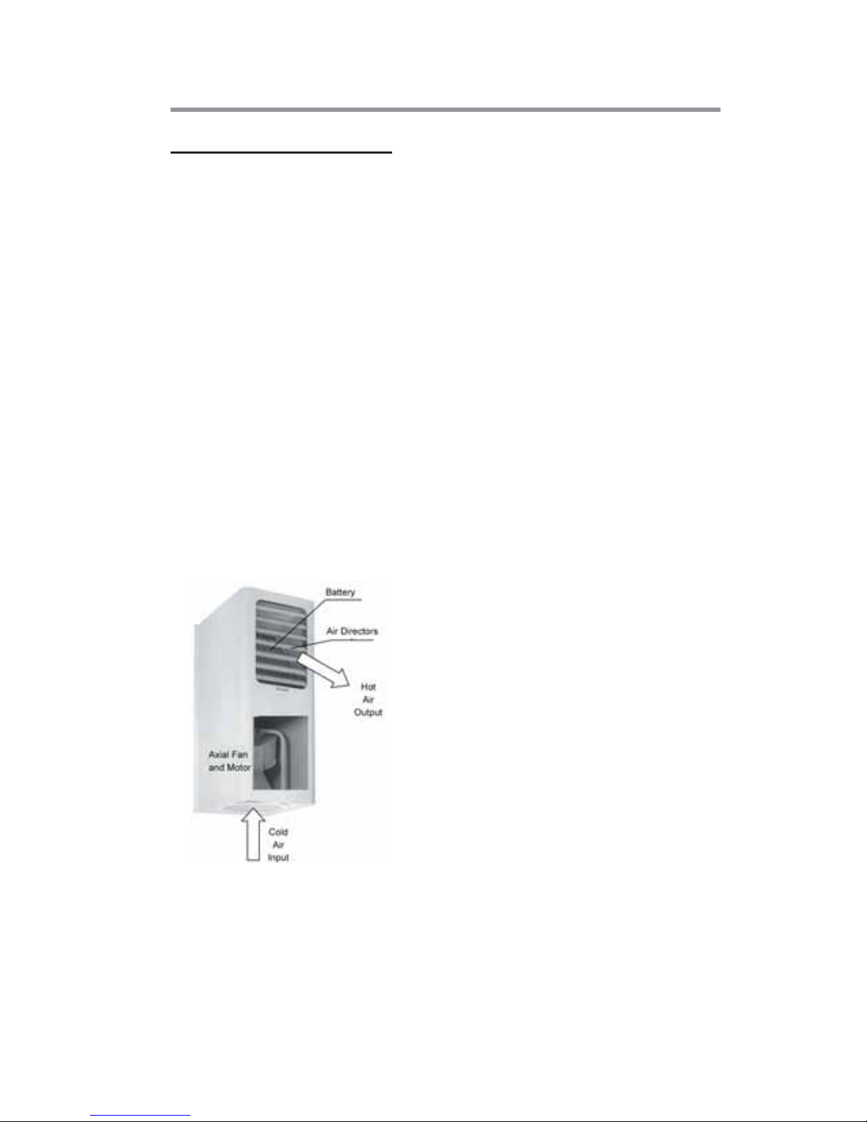
The objective of the apparatus is to heat the ambient air using water
and vapor. The apparatus consists of three main parts; (Figure 1)
1. Coil
2. Fan
3. Air Directors
Coil: Hot water or vapor circulates in the coil. It consists of
aluminum or steel fins arranged on copper or steel pipe in order
to increase the heat transfer surface.
Fan and Motor: It is located under the coil. As the fan
operates, the heat in the coil is more rapidly transferred into
ambient.
Air Directors: It helps direction of the air blown by the fan.
Figure 1: Main parts of the heater
Page 7
8
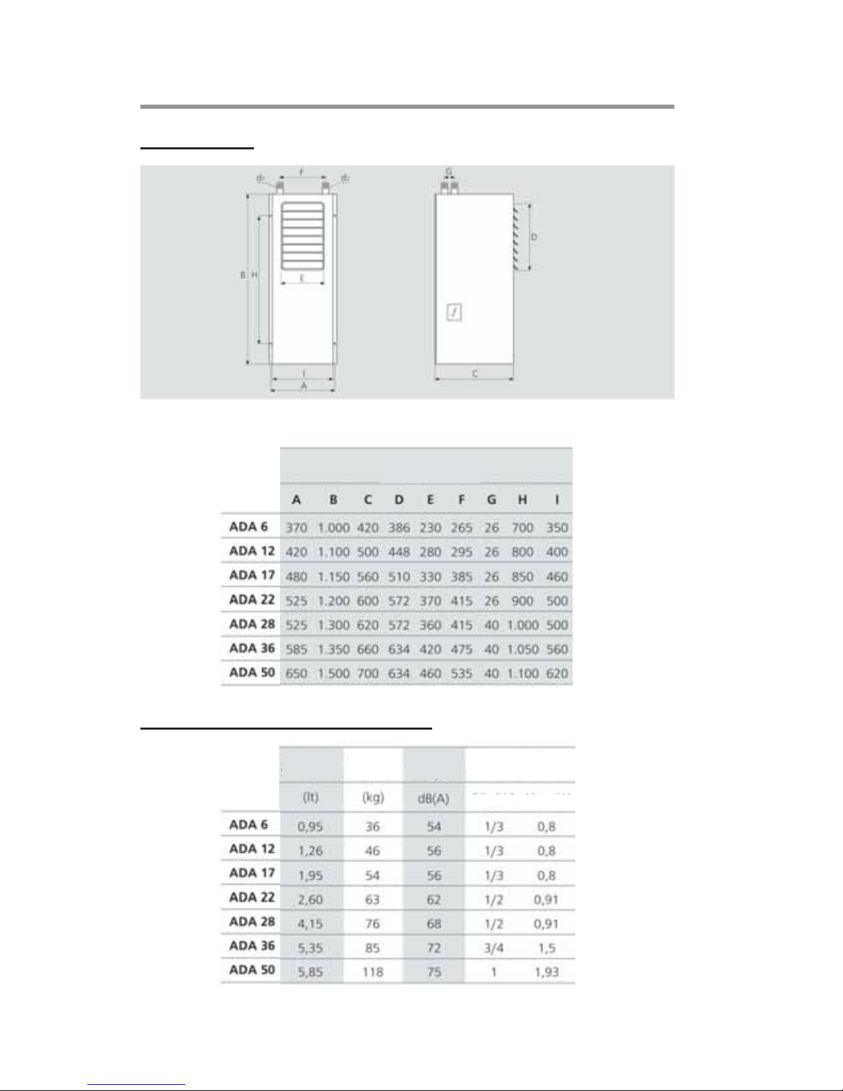
Dimensions
Dimensions
(mm)
(mm)
Dimensions
Coil
Coil
Water Vol.
Water Vol.
Sound
Sound
Level
Level
Electricity 380V,
3 phases
Working
Weight
Power (W) Current (a)
Other Technical Characteristics
Page 8
9
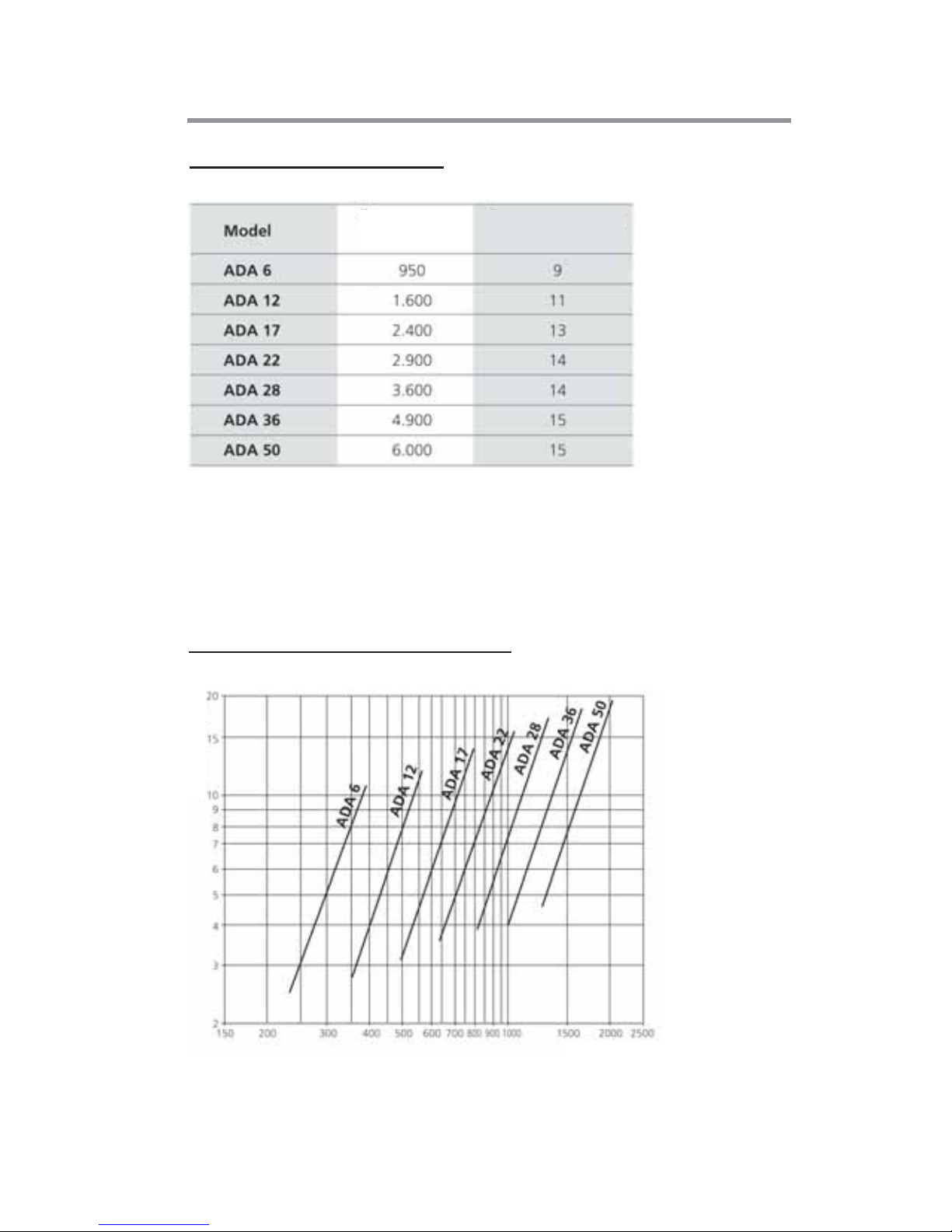
Air Flow
(m
3
/hour)
Air Throw
(meter)
Not: Throwing distances are at straight angle with the fan and at the distance
where the 0,2 meter/second air velocity is measured at the ambient temperature
of 18°C.
Water Flow (m3/hour)
Pressure Drop (Kpa)
Air Distribution Distances
Coil Water Pressure Drop Graphic
Page 9
10
Installation Rules
Location Selection and Mounting
The heater should be mounted in a closed area where it shall not
be exposed to outer effects like rain, frost. The fan section of the
unit should be accessible.
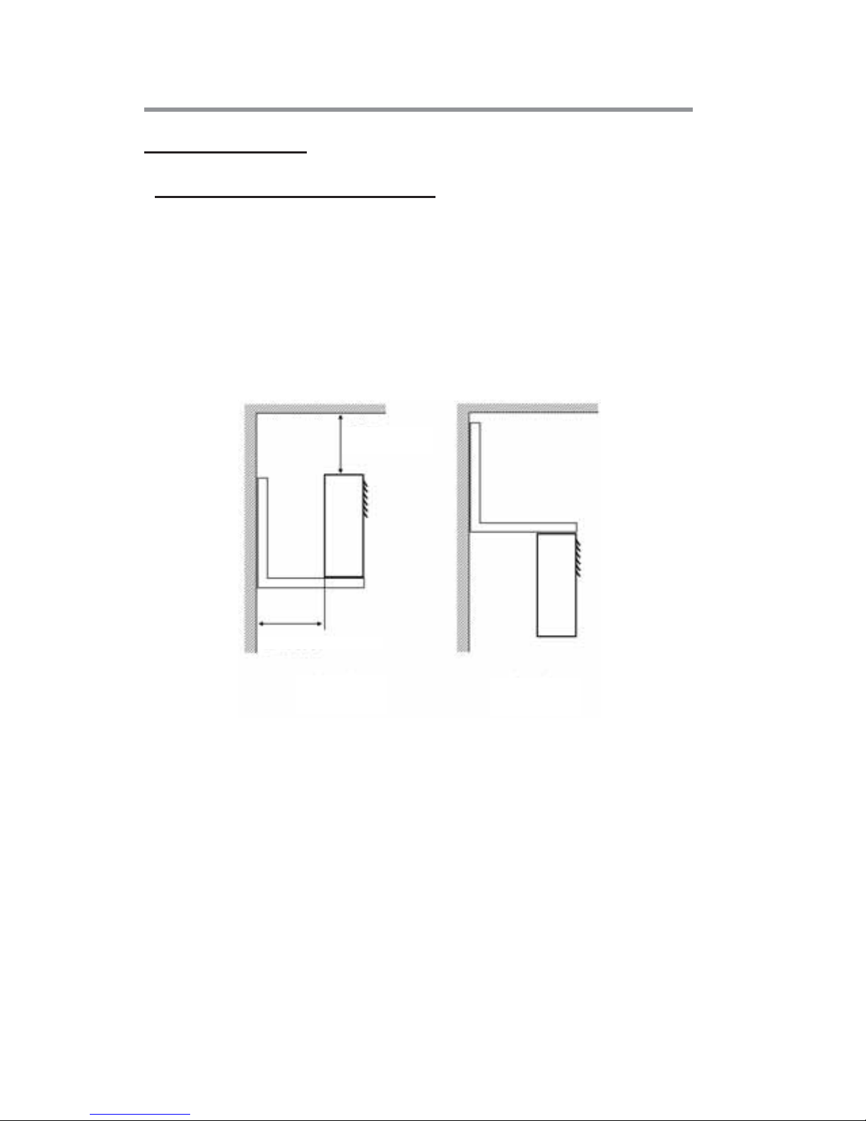
The wall-mounting or ceiling-mounting of the heater should be
performed in different ways. The examples are illustrated in Figure
2. The hanging legs can be both secured by the client or bought as
ready from Alarko.
Sufficient space should be left between the heater and wall orceiling
for that the air emission can be realized easily and the motor can
be serviced easily as required.
It is at the user’s disposal weather the heater shall be placed on the
brackets or hanged.
Generally, they are hanged. Hanging has two advantageous. 1.
Since the legs are on the apparatus, they are not visible; they do not
destroy the decorative look. 2. When it is placed, there is a possibility
that the cartoons, sags be put between the wall and the heater. But, if
it is hanged, no material can be placed between the wall and heater.
Placing the
heater
Hanging the
heater
Min.
35 cm
Figure 2: Wall-mounting alternatives for the apparatus
Min. 35 cm
Page 10
11
Thus, the possibility of them to block the fan is eliminated.
Water Pipes Installation
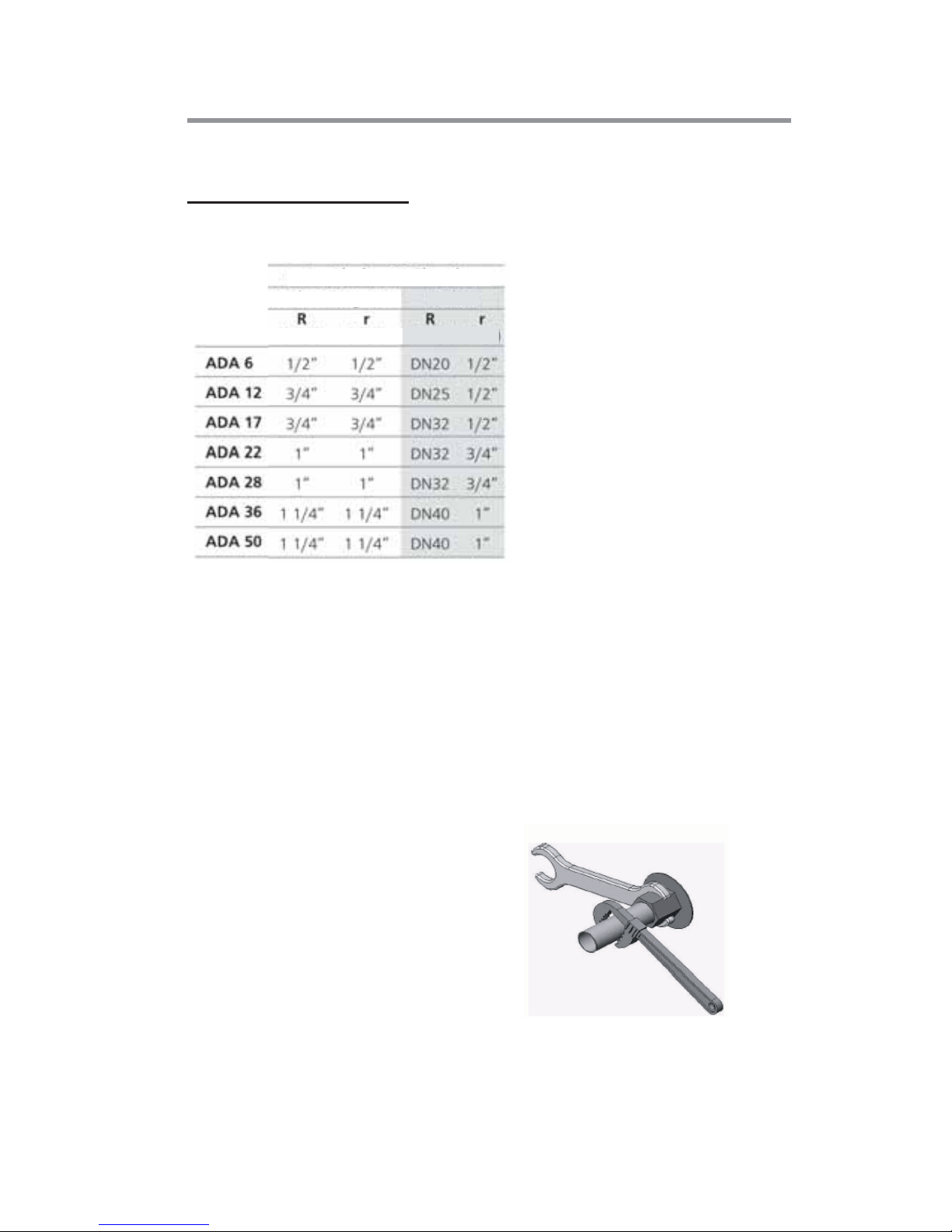
Please, find water pipe diameters we suggest in the Table 1.
Inserting valve at water inlets and outlets is advantageous.
These valves can be heat system valves or spherical valves.
Attention should be paid that the water flow ratio allowed by the
valves should be appropriate for the water flow ratio to pass in
the heater.
While the coil water pipe connections are made, attention
should be paid that the pipe connections be loose not to give
way to any force or stress. Use of flexible fixings (if possible) in
pipe connections is advantageous. After the connections are
completed, leak and stress test
should be applied.
Countertightening should be
applied as shown in Figure 3
during the pipe connection. The
inlets and outlets of the heater
are not strong enough to resist
the tightening.
Table 1
Heating Liquid Connections
Steam
(Threaded) (Threaded)
(Flanged)(Threaded)
ekil 3: Cihaza boru balants yaplrken
"kontra skma" uygulamas yaplmas
Figure 3: “Counter-tightening” as the pipe connections
are made
Hot Water
Page 11
12
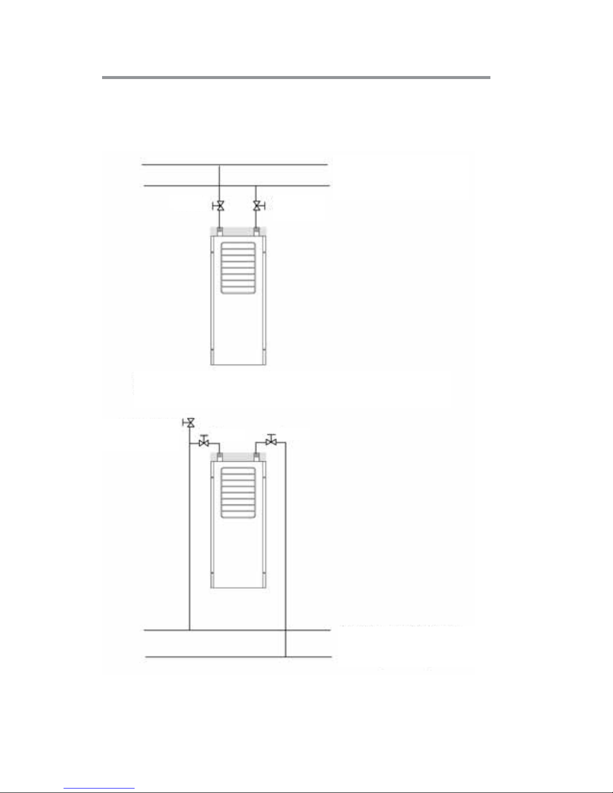
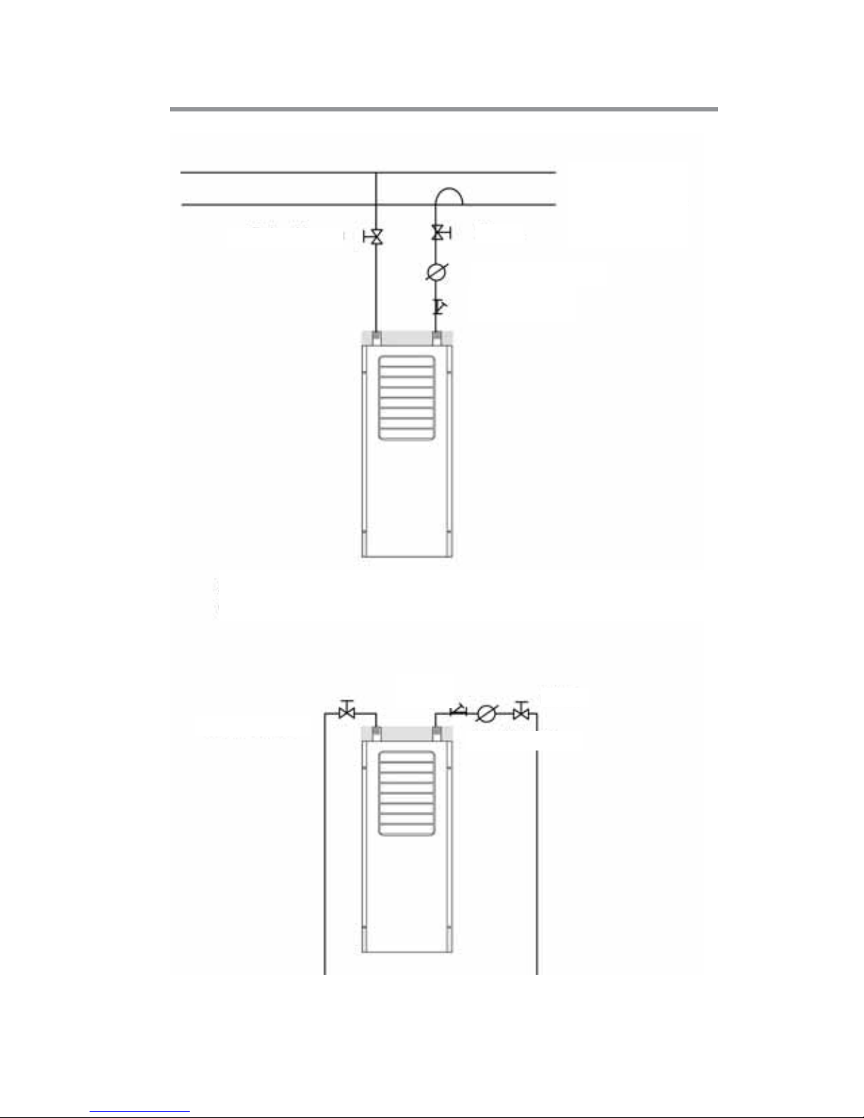
Figure 4 and 5 illustrates various alternatives for connections.
These illustrations are just suggestions; the installation should be
made by qualified personnel.
Figure 4B: Connection to hot water
installation The case when the heater is above
the main pipes
Hot water flow pipe
Hot water return pipe
Figure 4A: Connection to hot water
installation The case of the heater under the
main pipes
Hot water flow pipe
Hot water return pipe
Valve
Valve
Air Discharge
Valve (Purger)
Valve
Valve
Valve
Page 12
13
Valve
Steam Valve
Steam Pipe
Condensation
pipe
Condenstop
Figure 5A: Connection to steam installation.
The case when the heater is lower than the condensation pipe
Figure 5B: Connection to steam installation.
The case when the heater is higher than the condensation pipe
Valve
Steam Valve
Dirt
Keeper
Filter
Condenstop
Page 13

14
Electricity:
All electrical connections should be made by a qualified
electrician.
The fan motors of the heater operate with 380 V, 50 Hz power.
Page 14
15
Trouble-shooting Manual
If the unit does not operate:
Is it plugged?
Is there power in the plug?
Are the fuses OK?
Is there any mains power cut?
Does the propeller turns?
If the unit does not heat enough:
See if the coil surface is dirty or air suction is low.
If it is operated with a thermostat, see if the thermostat is wrongly adjusted.
See if there is any open door or window.
See if there air in water circuit.
There may not be enough hot water in water circuit.
See if the pipes of the heat coil are plugged.
There may be plastic bag, paper etc. stuck on the coil surface.
See if the propeller is dirty or its balance is disordered.
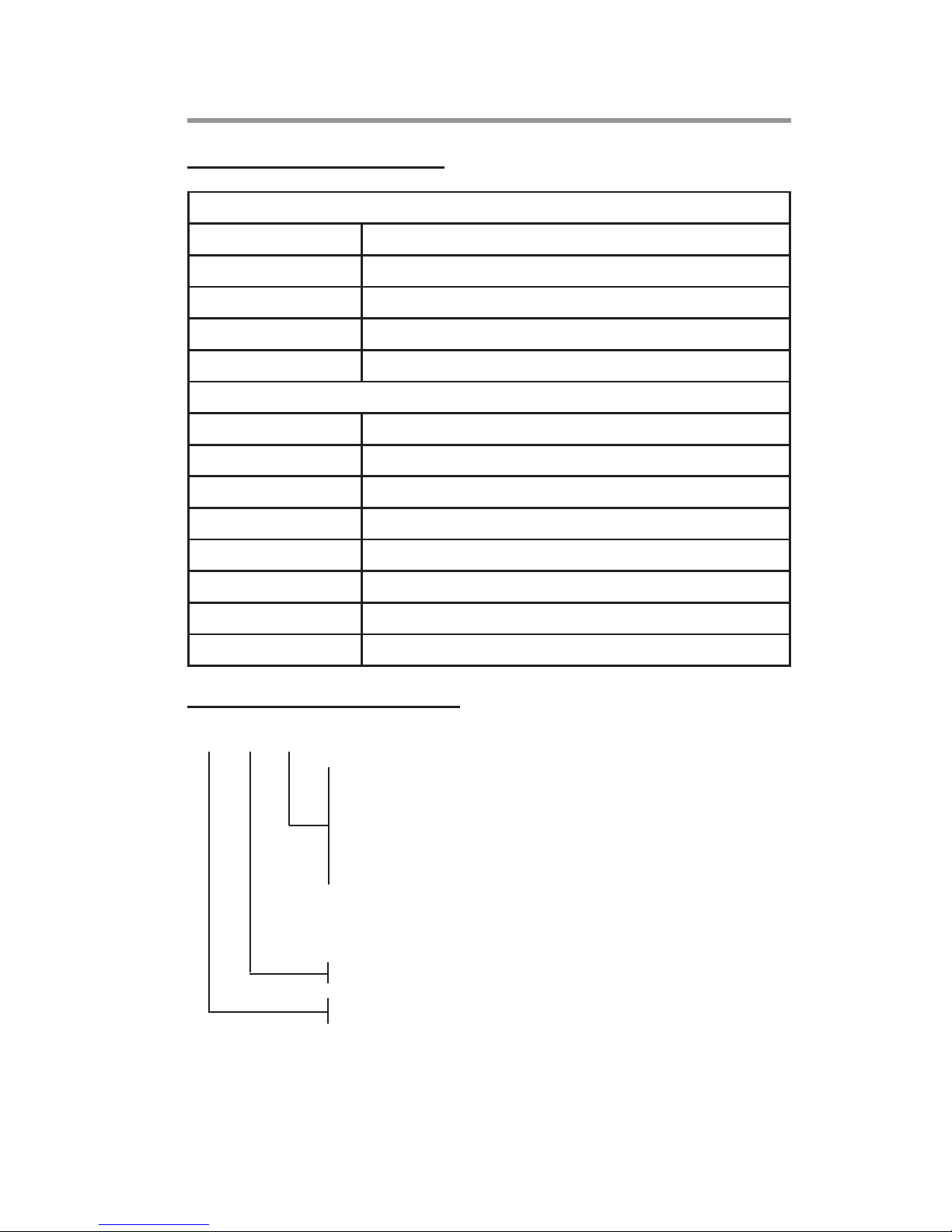
Product Ordering Notation
ADA 36 S
S (for hot water and max. 2,5 atu steam,
copper pipe - aluminum fin)
K (for red-hot water and max. 2,5 -5 atu steam,
pipe - aluminum fin)
Ç (for 5 -10 atu steam, steel pipe - steel fin)
Model
Fan Unit Heater
Page 15

: GOSB - Gebze Org. San. Bölgesi, Ş. Bilgisu Cad. 41480 Gebze-KOCAELİ
Tel: (0262) 648 60 00 - Fax: (0262) 648 60 08
: Sedat Simavi Sok. No: 48, 06550 Çankaya - ANKARA
Tel: (0312) 409 52 00 - Fax: (0312) 440 79 30
: Şehit Fethibey Cad. No : 55, Kat.13, 35210 Pasaport - İZMİR
Tel: (0232) 483 25 60 - Fax: (0232) 441 55 13
: Ziyapaşa Bulvarı Çelik Ap. No : 25/5-6, 01130 ADANA
Tel: (0322) 457 62 23 - Fax: (0322) 453 05 84
: Metin Kasapoğlu Cad. Küçükkaya Sitesi A Blok No: 1 D. 4, ANTALYA
Tel: (0242) 322 00 29 - Fax: (0242) 322 87 66
İSTANBUL
ANKARA
İZMİR
ADANA
ANTALYA
web: www.alarko-carrier.com.tr
e-posta: [email protected]
MDH: 444 0 128
 Loading...