

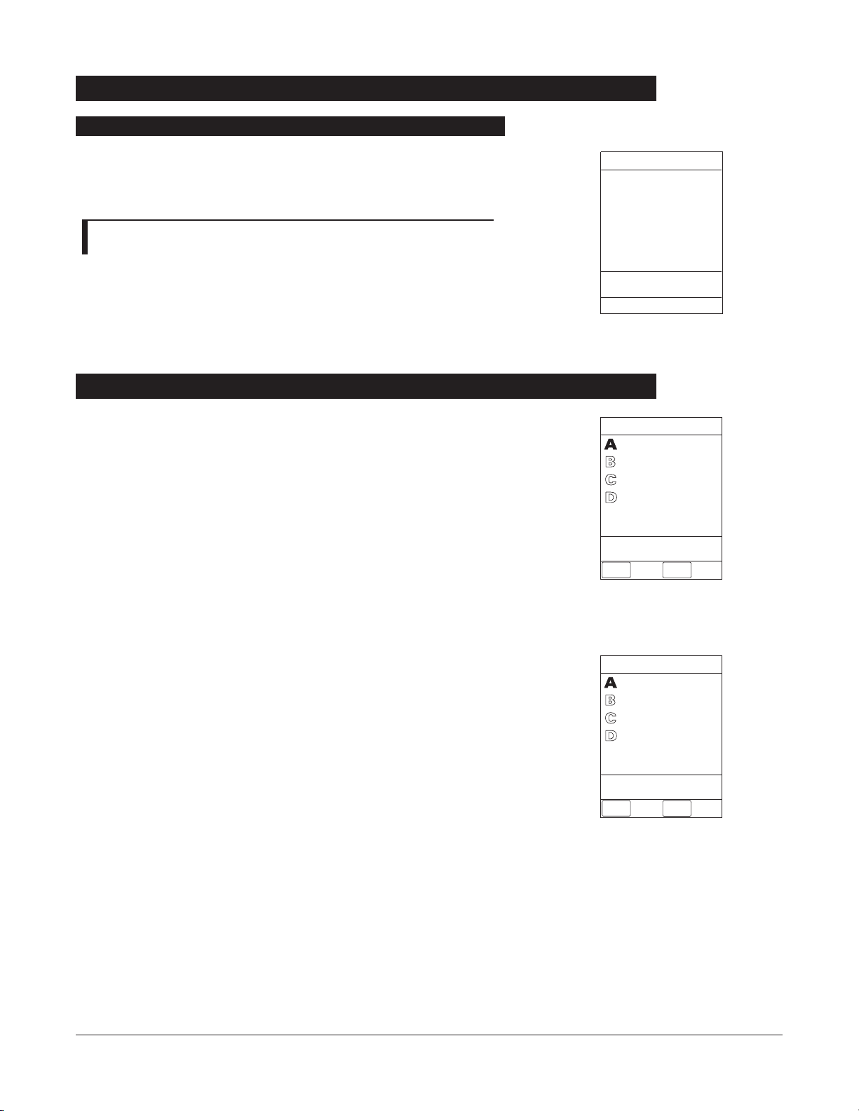
DIRECTIONS FOR USE
MEDICATION SAFETY SYSTEM
PROGRAMMING MODULE
OPTIONS
SILENCE
CLEAR
1
4
7
5
8
0
2
9
6
.
3
CANCEL
ENTER
SYSTEM
ON
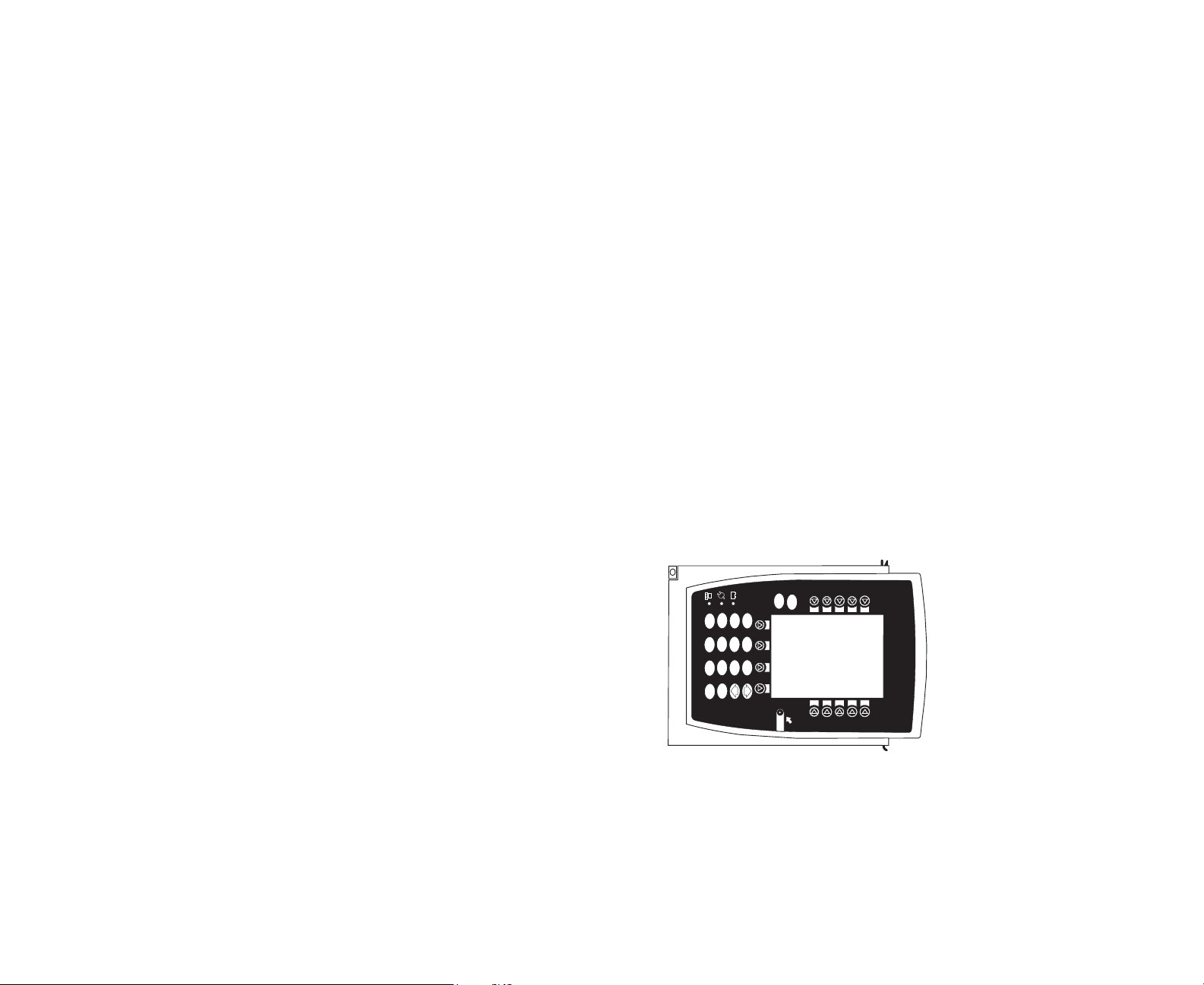
8000 Series
Medley™
8000 SERIES
PROGRAMMING MODULE


TABLE OF CONTENTS
INTRODUCTION
ABOUT THE SYSTEM . . . . . . . . . . . . . . . . . . . . . . . . . . . . . . . . . . . . . . . . . . . . . . . . . . . . . . . . . . . . . . . . . . . . . . . . . . . . . . . . . . . . . . . . . 1
FEATURES AND DEFINITIONS . . . . . . . . . . . . . . . . . . . . . . . . . . . . . . . . . . . . . . . . . . . . . . . . . . . . . . . . . . . . . . . . . . . . . . . . . . . . . . . 2
SYMBOLS . . . . . . . . . . . . . . . . . . . . . . . . . . . . . . . . . . . . . . . . . . . . . . . . . . . . . . . . . . . . . . . . . . . . . . . . . . . . . . . . . . . . . . . . . . . . . . . . . . . . . . 4
GETTING STARTED
WARNINGS AND CAUTIONS . . . . . . . . . . . . . . . . . . . . . . . . . . . . . . . . . . . . . . . . . . . . . . . . . . . . . . . . . . . . . . . . . . . . . . . . . . . . . . . . 5
CONTROLS AND INDICATORS
. . . . . . . . . . . . . . . . . . . . . . . . . . . . . . . . . . . . . . . . . . . . . . . . . . . . . . . . . . . . . . . . . . . . . . . . . . . . . . 8
INSTALLATION
. . . . . . . . . . . . . . . . . . . . . . . . . . . . . . . . . . . . . . . . . . . . . . . . . . . . . . . . . . . . . . . . . . . . . . . . . . . . . . . . . . . . . . . . . . . . . . . . 10
Unpacking Programming Module
. . . . . . . . . . . . . . . . . . . . . . . . . . . . . . . . . . . . . . . . . . . . . . . . . . . . . . . . . . . . . . . . . . . . . . . . 10
ATTACHING AND DETACHING CHANNELS
. . . . . . . . . . . . . . . . . . . . . . . . . . . . . . . . . . . . . . . . . . . . . . . . . . . . . . . . . . . . . . . . 11
Attaching Channel(s)
. . . . . . . . . . . . . . . . . . . . . . . . . . . . . . . . . . . . . . . . . . . . . . . . . . . . . . . . . . . . . . . . . . . . . . . . . . . . . . . . . . . . . 11
Detaching Channel(s)
. . . . . . . . . . . . . . . . . . . . . . . . . . . . . . . . . . . . . . . . . . . . . . . . . . . . . . . . . . . . . . . . . . . . . . . . . . . . . . . . . . . . . 11
Adding Channel(s) While System is Powered On
. . . . . . . . . . . . . . . . . . . . . . . . . . . . . . . . . . . . . . . . . . . . . . . . . . . . . . . . 12
DISPLAYS . . . . . . . . . . . . . . . . . . . . . . . . . . . . . . . . . . . . . . . . . . . . . . . . . . . . . . . . . . . . . . . . . . . . . . . . . . . . . . . . . . . . . . . . . . . . . . . . . . . . . . 12
Main Display
. . . . . . . . . . . . . . . . . . . . . . . . . . . . . . . . . . . . . . . . . . . . . . . . . . . . . . . . . . . . . . . . . . . . . . . . . . . . . . . . . . . . . . . . . . . . . . 12
Adjusting Display Contrast
. . . . . . . . . . . . . . . . . . . . . . . . . . . . . . . . . . . . . . . . . . . . . . . . . . . . . . . . . . . . . . . . . . . . . . . . . . . . . . . 13
START-UP . . . . . . . . . . . . . . . . . . . . . . . . . . . . . . . . . . . . . . . . . . . . . . . . . . . . . . . . . . . . . . . . . . . . . . . . . . . . . . . . . . . . . . . . . . . . . . . . . . . . . . 14
Powering On System
. . . . . . . . . . . . . . . . . . . . . . . . . . . . . . . . . . . . . . . . . . . . . . . . . . . . . . . . . . . . . . . . . . . . . . . . . . . . . . . . . . . . . . 14
Responding to Maintenance Reminder
. . . . . . . . . . . . . . . . . . . . . . . . . . . . . . . . . . . . . . . . . . . . . . . . . . . . . . . . . . . . . . . . . . 15
Selecting New Patient and Profile Options
. . . . . . . . . . . . . . . . . . . . . . . . . . . . . . . . . . . . . . . . . . . . . . . . . . . . . . . . . . . . . . . 15
Entering Patient ID
. . . . . . . . . . . . . . . . . . . . . . . . . . . . . . . . . . . . . . . . . . . . . . . . . . . . . . . . . . . . . . . . . . . . . . . . . . . . . . . . . . . . . . . . 18
Modifying Patient ID
. . . . . . . . . . . . . . . . . . . . . . . . . . . . . . . . . . . . . . . . . . . . . . . . . . . . . . . . . . . . . . . . . . . . . . . . . . . . . . . . . . . . . . 19
ADJUSTING AUDIO VOLUME
. . . . . . . . . . . . . . . . . . . . . . . . . . . . . . . . . . . . . . . . . . . . . . . . . . . . . . . . . . . . . . . . . . . . . . . . . . . . . . . 21
SETTING UP TIME OF DAY . . . . . . . . . . . . . . . . . . . . . . . . . . . . . . . . . . . . . . . . . . . . . . . . . . . . . . . . . . . . . . . . . . . . . . . . . . . . . . . . . . . 21
REVIEWING SYSTEM CONFIGURATION . . . . . . . . . . . . . . . . . . . . . . . . . . . . . . . . . . . . . . . . . . . . . . . . . . . . . . . . . . . . . . . . . . . . 22
REVIEWING SERIAL NUMBER . . . . . . . . . . . . . . . . . . . . . . . . . . . . . . . . . . . . . . . . . . . . . . . . . . . . . . . . . . . . . . . . . . . . . . . . . . . . . . . 23
REVIEWING SOFTWARE VERSION . . . . . . . . . . . . . . . . . . . . . . . . . . . . . . . . . . . . . . . . . . . . . . . . . . . . . . . . . . . . . . . . . . . . . . . . . . 24
VIEWING AND CLEARING GUARDRAILS®EVENT COUNTER
. . . . . . . . . . . . . . . . . . . . . . . . . . . . . . . . . . . . . . . . . . . . 25
POWERING OFF
. . . . . . . . . . . . . . . . . . . . . . . . . . . . . . . . . . . . . . . . . . . . . . . . . . . . . . . . . . . . . . . . . . . . . . . . . . . . . . . . . . . . . . . . . . . . . . . 25
Powering Off System
. . . . . . . . . . . . . . . . . . . . . . . . . . . . . . . . . . . . . . . . . . . . . . . . . . . . . . . . . . . . . . . . . . . . . . . . . . . . . . . . . . . . . 25
Powering Off Channel
. . . . . . . . . . . . . . . . . . . . . . . . . . . . . . . . . . . . . . . . . . . . . . . . . . . . . . . . . . . . . . . . . . . . . . . . . . . . . . . . . . . . 26
LOCKING/UNLOCKING TAMPER RESIST . . . . . . . . . . . . . . . . . . . . . . . . . . . . . . . . . . . . . . . . . . . . . . . . . . . . . . . . . . . . . . . . . . . . 26
COMPUTER LINK . . . . . . . . . . . . . . . . . . . . . . . . . . . . . . . . . . . . . . . . . . . . . . . . . . . . . . . . . . . . . . . . . . . . . . . . . . . . . . . . . . . . . . . . . . . . . . 27
ALARMS, ERRORS, MESSAGES
DEFINITIONS . . . . . . . . . . . . . . . . . . . . . . . . . . . . . . . . . . . . . . . . . . . . . . . . . . . . . . . . . . . . . . . . . . . . . . . . . . . . . . . . . . . . . . . . . . . . . . . . . . 29
AUDIO CHARACTERISTICS . . . . . . . . . . . . . . . . . . . . . . . . . . . . . . . . . . . . . . . . . . . . . . . . . . . . . . . . . . . . . . . . . . . . . . . . . . . . . . . . . . . 30
ALARMS . . . . . . . . . . . . . . . . . . . . . . . . . . . . . . . . . . . . . . . . . . . . . . . . . . . . . . . . . . . . . . . . . . . . . . . . . . . . . . . . . . . . . . . . . . . . . . . . . . . . . . . 31
ERRORS . . . . . . . . . . . . . . . . . . . . . . . . . . . . . . . . . . . . . . . . . . . . . . . . . . . . . . . . . . . . . . . . . . . . . . . . . . . . . . . . . . . . . . . . . . . . . . . . . . . . . . . . 32
MESSAGES
. . . . . . . . . . . . . . . . . . . . . . . . . . . . . . . . . . . . . . . . . . . . . . . . . . . . . . . . . . . . . . . . . . . . . . . . . . . . . . . . . . . . . . . . . . . . . . . . . . . .
33
MAINTENANCE
SPECIFICATIONS . . . . . . . . . . . . . . . . . . . . . . . . . . . . . . . . . . . . . . . . . . . . . . . . . . . . . . . . . . . . . . . . . . . . . . . . . . . . . . . . . . . . . . . . . . . . . . 35
SYSTEM CONFIGURABLE SETTINGS
. . . . . . . . . . . . . . . . . . . . . . . . . . . . . . . . . . . . . . . . . . . . . . . . . . . . . . . . . . . . . . . . . . . . . . . . 36
INTRODUCTION GETTING STARTED ALARMS, ERRORS,
MESSAGES
MAINTENANCE
TABLE OF CONTENTS i

ii TABLE OF CONTENTS
MAINTENANCE (Continued)
STORAGE . . . . . . . . . . . . . . . . . . . . . . . . . . . . . . . . . . . . . . . . . . . . . . . . . . . . . . . . . . . . . . . . . . . . . . . . . . . . . . . . . . . . . . . . . . . . . . . . . . . . . . 37
BATTERY CARE AND MAINTENANCE . . . . . . . . . . . . . . . . . . . . . . . . . . . . . . . . . . . . . . . . . . . . . . . . . . . . . . . . . . . . . . . . . . . . . . 37
Battery Type and Charging
. . . . . . . . . . . . . . . . . . . . . . . . . . . . . . . . . . . . . . . . . . . . . . . . . . . . . . . . . . . . . . . . . . . . . . . . . . . . . . . 37
Battery Charge
. . . . . . . . . . . . . . . . . . . . . . . . . . . . . . . . . . . . . . . . . . . . . . . . . . . . . . . . . . . . . . . . . . . . . . . . . . . . . . . . . . . . . . . . . . . . 37
Battery Care
. . . . . . . . . . . . . . . . . . . . . . . . . . . . . . . . . . . . . . . . . . . . . . . . . . . . . . . . . . . . . . . . . . . . . . . . . . . . . . . . . . . . . . . . . . . . . . . 38
Battery Cautions and Disposal
. . . . . . . . . . . . . . . . . . . . . . . . . . . . . . . . . . . . . . . . . . . . . . . . . . . . . . . . . . . . . . . . . . . . . . . . . . . . 38
CLEANING . . . . . . . . . . . . . . . . . . . . . . . . . . . . . . . . . . . . . . . . . . . . . . . . . . . . . . . . . . . . . . . . . . . . . . . . . . . . . . . . . . . . . . . . . . . . . . . . . . . . . 39
INSPECTION REQUIREMENTS . . . . . . . . . . . . . . . . . . . . . . . . . . . . . . . . . . . . . . . . . . . . . . . . . . . . . . . . . . . . . . . . . . . . . . . . . . . . . . . 40
SERVICE INFORMATION . . . . . . . . . . . . . . . . . . . . . . . . . . . . . . . . . . . . . . . . . . . . . . . . . . . . . . . . . . . . . . . . . . . . . . . . . . . . . . . . . . . . .
41
Customer Service
. . . . . . . . . . . . . . . . . . . . . . . . . . . . . . . . . . . . . . . . . . . . . . . . . . . . . . . . . . . . . . . . . . . . . . . . . . . . . . . . . . . . . . . . . 41
Technical Support
. . . . . . . . . . . . . . . . . . . . . . . . . . . . . . . . . . . . . . . . . . . . . . . . . . . . . . . . . . . . . . . . . . . . . . . . . . . . . . . . . . . . . . . . .
41
Product Return
. . . . . . . . . . . . . . . . . . . . . . . . . . . . . . . . . . . . . . . . . . . . . . . . . . . . . . . . . . . . . . . . . . . . . . . . . . . . . . . . . . . . . . . . . . . . 41
WARRANTY . . . . . . . . . . . . . . . . . . . . . . . . . . . . . . . . . . . . . . . . . . . . . . . . . . . . . . . . . . . . . . . . . . . . . . . . . . . . . . . . . . . . . . . . . . . . . . . . . . . 42

GENERAL CONTACT INFORMATION
Customer Advocacy
For clinical and technical questions, feedback, and troubleshooting assistance.
Phone, toll-free, within the United States and Canada: (800) 854-7128, Ext. 7812
E-Mail: CustomerFeedback@alarismed.com
Technical Support
For technical information related to maintenance procedures and service manual support.
For more detailed information, refer to the “Service Information” section of this document.
United States:
Phone:
(858) 458-6003
Toll-free: (800) 854-7128, Ext. 6003
Canada:
Phone, Toll-free:
Eastern: (800) 908-9918
Western: (800) 908-9919

THIS PAGE
INTENTIONALLY
LEFT BLANK

INTRODUCTION
INTRODUCTION 1
The Medley™ Medication Safety System is a modular infusion
and monitoring system intended for use in today’s growing
professional healthcare environment, for use in adult, pediatric
and neonatal care.
The Medley™ Medication Safety System consists of the
Programming Module (
8000
Series), the Guardrails
®
Safety
Software, and up to four detachable modules (or “channels”)
which provide infusion or monitoring capabilities.
The Medley™ Programming Module is the core of the Medley™
System and provides a common user interface for programming
infusions and monitoring, which helps to reduce complexity at
the point of care.
NOTE: The Medley™ Programming Module name will be changing
in the near future to Medley™ Point-of-Care Unit.
Guardrails®Safety Software for the Medley™ System brings a
new level of medication error prevention to the point of patient
care. The Guardrails
®
Safety Software features medication
dosing guidelines for up to ten patient-specific care areas,
referred to as profiles. Each profile contains a specific drug
library and channel labels, as well as instrument configurations
appropriate for the care area. Optional drug-specific Guardrails
®
Clinical Advisories provide visual messages. Dosing limits for
each drug entry may be either Guardrails
®
Hard Limits that
cannot be overridden during infusion programming or
Guardrails
®
Soft Limits that can be overridden, based on clinical
requirements.
A data set is developed and approved by the facility’s own multidisciplinary team using the Guardrails®Editor, the PC-based
authoring tool. A data set is then electronically transferred to
the Medley™ System by qualified personnel. The approved data
sets are maintained by the Guardrails
®
Editor for future updates
and reference.
Information about Guardrails
®
Alerts that occur during use is
stored within the Medley™ Programming Module, and can be
accessed using the Guardrails
®
Continuous Quality Improvement
(
CQI) Event Tracker and Guardrails
®
CQI
Event Reporter.
This document provides directions for use for the Medley™
Programming Module. Read all instructions before using the
Medley™ System. For additional operating instructions,
indications for use and contraindications, refer to the Directions
for Use for the individual system module(s).
About the System
INTRODUCTION

2 INTRODUCTION
Refer to the “Alarms, Errors, Messages” chapter of this Directions for Use for the definitions of various
alerts. Refer to the Directions for Use that applies to the attached Medley™ Module(s) for features and
definitions specific to that module.
Anesthesia Mode The Anesthesia Mode allows the anesthesiologist to access additional
drugs, in each profile, that are appropriate to anesthesiology. It also
features permanent pause.
Battery Run Time Display The Battery Run Time Display appears on the Main Display prompt bar
when the Programming Module is disconnected from
AC. If enabled,
this feature provides a visual display of the estimated remaining battery
run time under the current operating conditions, when operating on
battery.
Data Set A data set is created using the Guardrails
®
Editor authoring tool and
then electronically transferred to the Medley™ Programming Module.
A data set reflects the facility’s best-practice guidelines for
IV drug
administration and includes: profile drug libraries, clinical advisories,
instrument configurations, and channel label libraries.
Dose Checking The Always Dose Checking option causes a Guardrails
®
Soft Alert to
occur each time a dose limit is exceeded. The drug label in the Channel
Message Display provides an indicator (“
↑↑↑” or “LLL”) that the infusion
is beyond the current Guardrails
®
Soft Limit.
The Smart Dose Checking option causes an initial Guardrails
®
Soft Alert
to occur when a dose limit is exceeded. Subsequent programming
beyond the dose limit will not receive an alert. The drug label in the
Channel Message Display provides an indicator (“
↑↑↑” or “LLL”) if the
infusion is beyond the current Guardrails
®
Soft Limit.
Ease of Use To enhance safety and ease of operation, the Medley™ System provides
a full range of audio and visual alarms, errors, and messages.
Guardrails
®
Safety Software The Guardrails®Safety Software is designed to help prevent
programming errors by:
• Customizing device configurable settings to meet the need of the
selected hospital area/unit (profile).
• Comparing user programming with hospital-defined best-practice
guidelines.
• Providing a Guardrails
®
Prompt if an out-of-limits entry is made.
Features and Definitions

INTRODUCTION 3
Features and Definitions (Continued)
INTRODUCTION
Patient ID Entry An optional alphanumeric
16-character patient identifier can be
entered and displayed.
• When enabled, the
ID entry defaults to the Startup screen.
• When disabled, the
ID entry is only accessible from the System
Options screen.
Pole Clamp The Medley™ Programming Module pole clamp adapts to a wide
variety of surfaces, to provide versatility. The pole clamp features
include:
• Ergonomically designed knob.
• Accommodates diameters from
5
/8to 13/8inches (15.9 to 34.9 mm).
• Vertical or horizontal orientation, allowing it to adapt to both IV
poles and bed rails.
Profile A Profile is a unique set of system configuration settings and best-
practice guidelines for a specific patient population or patient type, and
consists of the following three components:
• Instrument configuration settings.
• A Guardrails
®
Drug Library, which includes drug names, standard
concentrations, dosing units, Guardrails
®
Limits, and optional
associated clinical advisories for both continuous and bolus dose
infusion.
• A Channel Label Library with text (alphanumeric) labels, that allows
identification of channels that are actively infusing nondrug
therapies (for example, saline or
TPN). Channel labels can also be
used to identify the route of delivery (for example, epidural).
Profile settings are established by the facility’s own multi-disciplinary
team prior to system implementation. Profile parameters are used to
create a data set, which is then electronically transferred to the
Programming Module.
System Configuration System Configurations allow system settings to be customized. If the
Profiles feature is enabled, the system settings defined for the selected
profile are automatically activated.
Tamper Resist The Tamper Resist feature provides a quick one-touch lockout of the
front panel keypad.
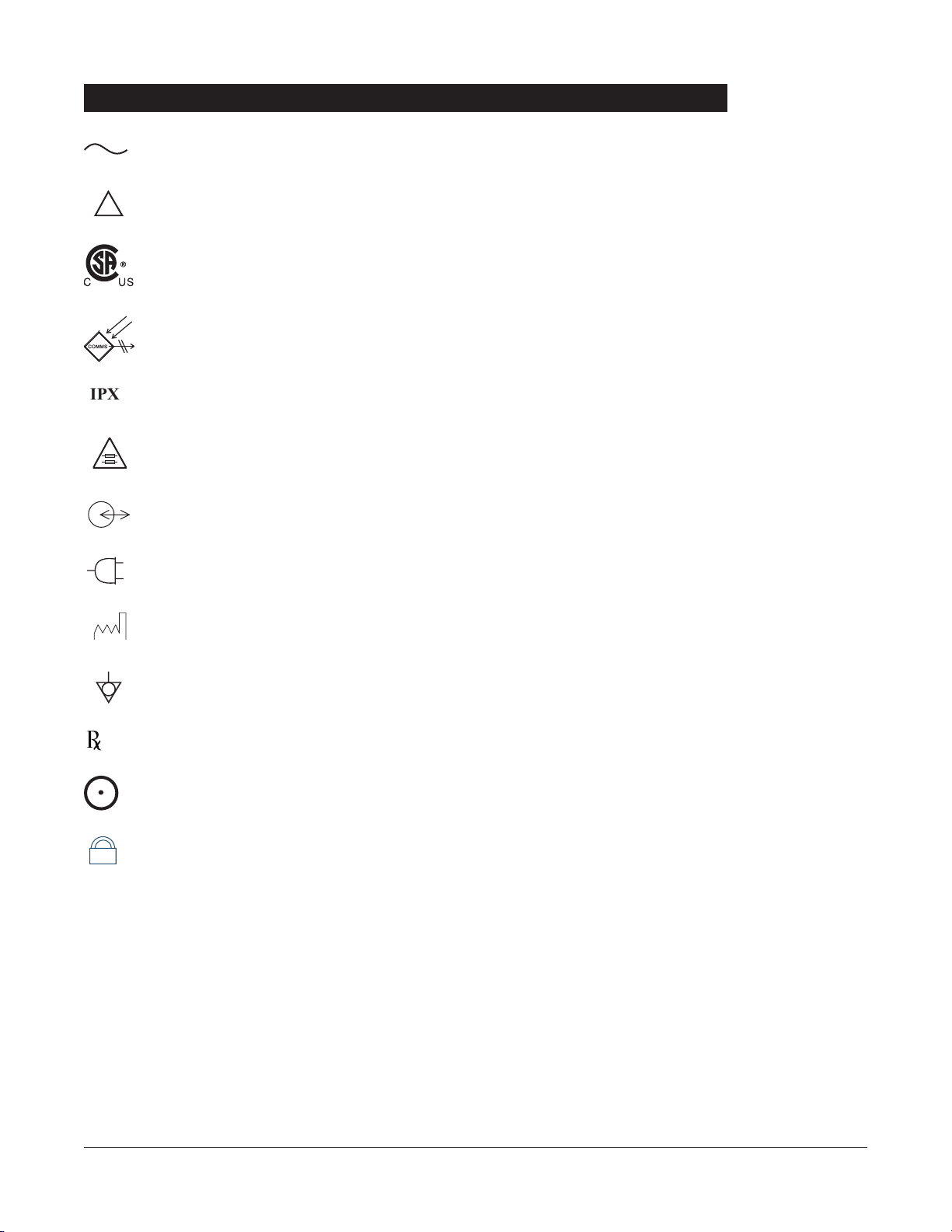
Alternating Current: Indicates that device should be attached to alternating current source,
50/
60 Hz only.
Attention: Refer to accompanying documentation.
Canadian and
U.S. Certification Mark: Products bearing this mark have been tested and
certified in accordance with applicable
U.S.
and Canadian electrical safety and performance
standards (
CSA C22.2 No.
601.1, UL 2601-1 and IEC 60601–2–24).
Communications Connector: For
RS-232 attachment.
Protection against fluid ingress: Drip Proof
Fuse Replacement: Replace fuse only with same type and rating.
IUI Connector: Inter-Unit Interface connector used to establish power and communications
between the Programming Module and attached modules.
Main Power: Connected to alternating current,
100-240 VAC.
Manufacturing Date: Number adjacent to symbol indicates the month and year of
manufacture.
Potential Equalization Conductor (if so equipped). Note: If the integrity of the
PEC or Hospital
Earth System is in question, operate the instrument using internal battery power.
CAUTION
: Federal (U.S.A.) law restricts this device to sale by or on the order of a physician.
“
SYSTEM ON”
Tamper Resist activate/deactivate switch.
4 INTRODUCTION
Symbols
+
75
IPX1
!
nly
O
MM-YYYY

NOTE: Although the Medley™ Medication Safety System is built
and tested to exacting specifications, it is not intended to replace
the supervision by medical personnel. The user should become
thoroughly familiar with the features and operation of the Medley™
System and exercise vigilance in its utilization.
GETTING STARTED
GETTING STARTED 5
GETTING STARTED
Warnings and Cautions
For WARNINGS and CAUTIONS for detachable module(s), refer to
the individual module’s Directions for Use.
To ensure proper performance of the Medley™ System and to
reduce potential injury, observe the following precautions:
When properly secured/snapped, the bottom latch provides a
very secure connection between modules. If not properly
latched, a module can be dislodged during operation.
WARNING
To ensure proper performance of the Medley™ System and to
reduce potential injury to the operator, observe the following
precautions:
• Always use a grounded, three wire receptacle. Where the
integrity of the protective earth grounding system is in doubt,
operate on internal battery.
• Disconnect from main (
AC) and battery power when
performing maintenance.
User Precautions
A warning is an alert to potential serious outcomes (death,
injury or serious adverse events) to the patient or user.
WARNING
A caution is an alert to take special care for the safe and
effective use of the device.
CAUTION
Do not use the Medley™ System in close proximity of Magnetic
Resonance Imaging (
MRI).
WARNING
O
nly
• The instrument case should only be opened by qualified
service personnel using proper grounding techniques.
Dropping/Jarring
Should an instrument be dropped or severely jarred, it should
be immediately taken out of use and inspected by qualified
service personnel, to ensure its proper function prior to reuse.
Operating Environment
Not for use in the presence of flammable anesthetics.
6 GETTING STARTED
Warnings and Cautions (Continued)
User Precautions (Continued)
Explosion hazard. Do not use in the
presence of flammable anesthetics.
DANGER
Electrical shock hazard. Do not open
case. Refer to qualified service
personnel.
WARNING

GETTING STARTED 7
GETTING STARTED
Use of accessories or cables other
than those specified may result in
degraded electromagnetic
compatibility performance of this
device.
WARNING
Warnings and Cautions (Continued)
User Precautions (Continued)
Radio Frequency Interference
Operating the system near equipment which radiates highenergy radio frequencies (electrosurgical/cauterizing
equipment, portable radios, cellular telephones, etc.) may
cause false alarm conditions. If this happens, reposition the
device away from the source of interference or turn off the
device and manually regulate the flow with the clamp and/or
monitor the vital parameters using an appropriate clinical
alternative.
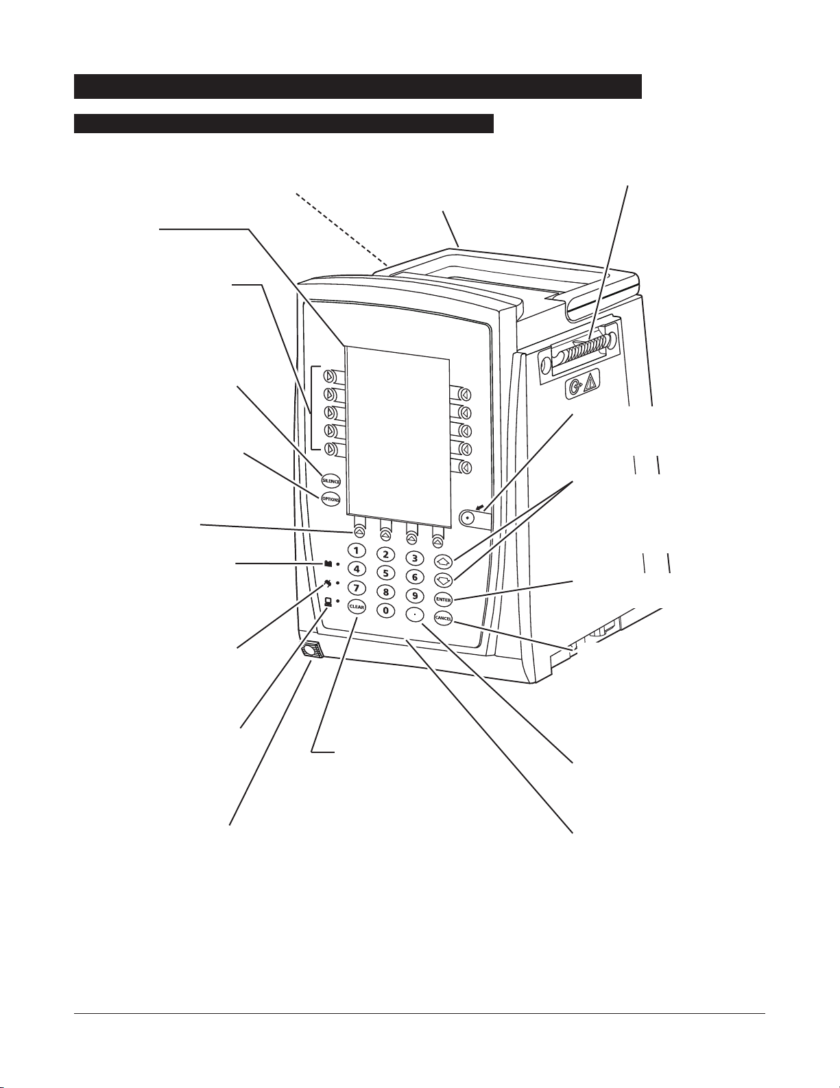
8 GETTING STARTED
IUI Connector, Left
(not visible)
SYSTEM
ON
Controls and Indicators
Front/Side View
Main Display
Soft Keys -
When pressed,
allows selection of options or
infusion parameters appearing
on Main Display adjacent to soft
key.
Silence Key -
When pressed
during an alarm, silences
audio for two minutes.
Options Key - When pressed,
allows access to available
System or Channel Options.
Soft Keys (see above).
Battery Indicator -
When
illuminated, indicates Medley™
System is operating on battery
power.
Power Indicator - When
illuminated, indicates Medley™
System is connected to an AC
power source.
Computer Monitor Mode
Indicator -
When illuminated,
indicates Medley™ System is
operating in Computer Monitor
mode.
Channel Release Latch -
When pressed, allows channel
to be removed.
Clear Key - When pressed,
clears current selected
parameter setting to “0”.
IUI Connector, Right
Handle
System On Key -
When pressed,
changes Medley™ System from
Standby to Operating mode.
Up/Down Arrows - When
pressed, will increase or decrease
parameter with each key press or
will scroll up and down when
pressed and held.
Enter Key - When pressed,
confirms current parameter entry.
Cancel Key - When pressed,
sequentially backs out of current
setup sequence.
Decimal Key - When pressed,
inserts a decimal point in numeric
data.
Numeric Keypad

GETTING STARTED 9
GETTING STARTED
Controls and Indicators (Continued)
Rear View
IUI Connector, Right IUI Connector, Left
Pole Clamp Knob
Primary Audio Speaker
Connector Plug over RJ45
Communication Data Port
Tamper Resist Switch
AC Power Cord Safety
Retainer
Power Cord Strap
Option Upgrade Panel
(for future use)
Handle
Use this bolt to reorient Pole
Clamp 90° for attachment to
a bed rail instead of a pole.

1. Remove Programming Module from its carton.
2. Check pole clamp for freedom of operation.
3. Check
AC power entry module for contamination.
4. Check for loose parts.
5. Plug module into an
AC outlet for 24 hours prior to use.
Maximum battery capacity, as well as gauge accuracy, is
reached after several charge/discharge/charge cycles. For
best results, fully charge/discharge/charge battery before
placing in use.
6. Perform Periodic Inspections (see “Inspection Requirements”
section in “Maintenance” chapter).
7. Perform check-in procedure [reference Medley™
Maintenance Software User Manual (included with
8970C,
or later) for details].
If the Programming Module is damaged, contact
ALARIS Medical
Systems for authorization to return the equipment for repair.
Instruments are tested and calibrated before they are packaged
for shipment. To ensure proper operation after shipment, it is
recommended that an incoming inspection be performed before
placing the instrument in use.
To enable the Profiles feature, a hospital-defined best-practice
data set must be uploaded to the Programming Module. Prior
to placing the Medley™ System in use, verify whether or not the
Profiles feature has been enabled (reference “Reviewing System
Configuration” section in “Getting Started” chapter).
10 GETTING STARTED
Unpacking Programming Module
Installation
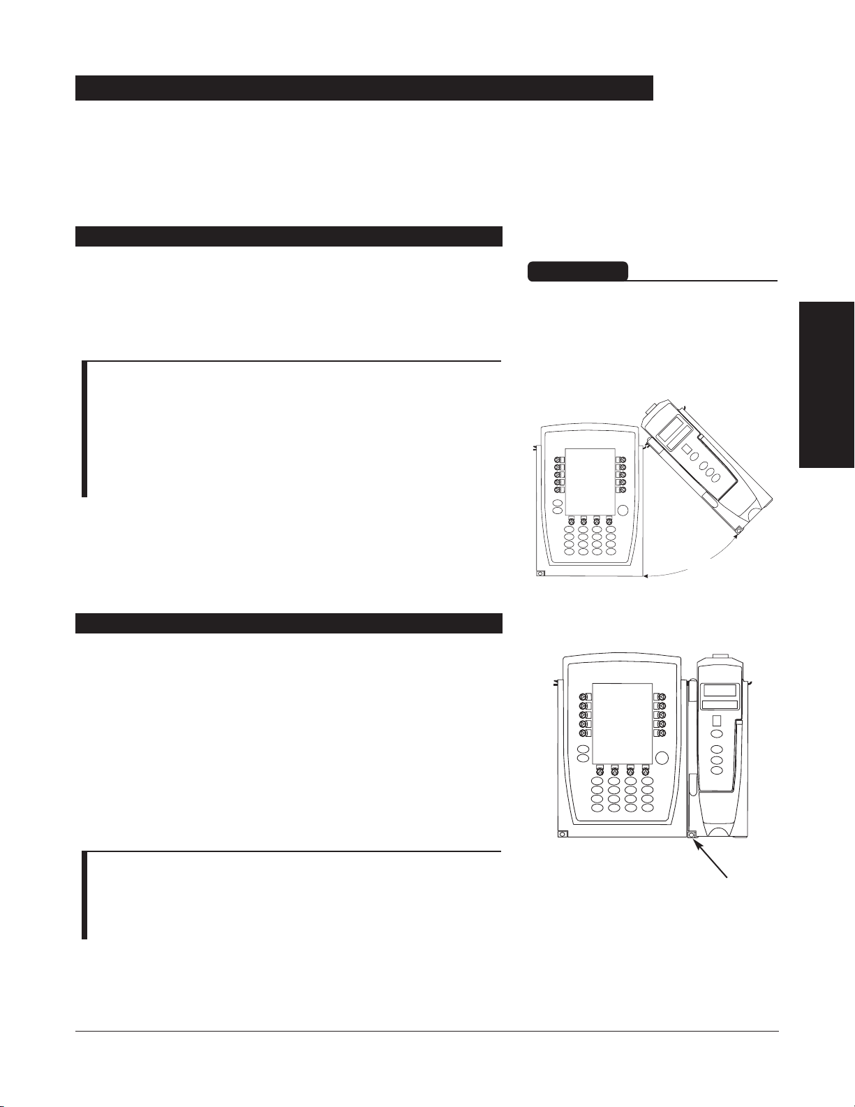
1. Position free channel at a
45°
angle, aligning IUI
Connectors.
2. Rotate free channel down against Programming Module or
attached channel, until bottom latch snaps in place.
NOTES:
• Individual hospitals may choose to permanently attach channels.
To remove permanently attached channels, contact qualified
service personnel.
• Application of adhesive tape or other materials to the sides of
the Programming Module and channels may prevent proper
latching.
Channels can be attached to either side of the Programming
Module or to either side of another channel. The process to
attach or detach is the same for either side, whether
attaching/detaching to/from a Programming Module or another
channel.
GETTING STARTED
11
GETTING STARTED
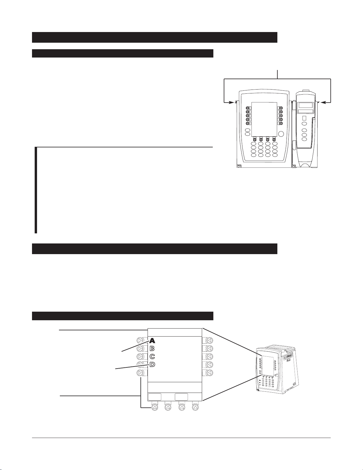
Attaching and Detaching Channels
Attaching Channel(s)
Detaching Channel(s)
1. Ensure channel(s) is powered off before detaching.
2. Push channel release latch (located directly below IUI
Connectors) and then rotate channel(s) up and away from
Programming Module or attached channel (opposite to
motion shown above) to disengage connectors.
• Medley™ System reidentifies and shows appropriate
channel identification (
A
, B, C or D), from left to right.
• Appropriate channel position(s) (A, B or C) for remaining
channel(s) appear on Main Display.
NOTE: The Medley™ Medication Safety System is designed to
operate a maximum of four channels. Channels added in excess of
four will not be recognized by the system. The channel(s) can be
attached in any position; however, when mounted on an IV pole, it
is recommended that a balanced configuration be maintained.
Release Latch
When properly secured/snapped, the
bottom latch provides a very secure
connection between modules. If not
properly latched, a module can be
dislodged during operation.
WARNING
45°
Add channel as described in “Attaching Channel(s)”.
• System tests channel, causing all
LED segments and Indicator
lights of channel displays to illuminate briefly.
• Appropriate channel identification display (A
, B, C or D)
illuminates. Channels are always labeled left to right, so if a
channel is added to left of other channels, all channels will be
reidentified. Channel reidentification does
NOT interrupt or
affect infusion or monitoring on active channels.
• Channel positions (A
, B, C or D) appear on Main Display.
NOTE: If any of the following conditions are observed, the
affected channel must be removed from use and inspected by
qualified personnel:
• LED segments are not illuminated on channel displays during
power-on test.
• Indicator lights do not illuminate.
• Appropriate channel identification (A, B, C or D) is not
displayed.
If the affected channel operates normally when it is attached via the
alternate IUI connector, it may be used until a replacement channel
can be substituted.
12 GETTING STARTED
The displays illustrated throughout this document are for
illustration purposes only. The display content will vary,
depending on configuration settings, hospital-defined data set
uploaded using the Guardrails
®
Safety Software, and many other
variables.
Attaching and Detaching Channels (Continued)
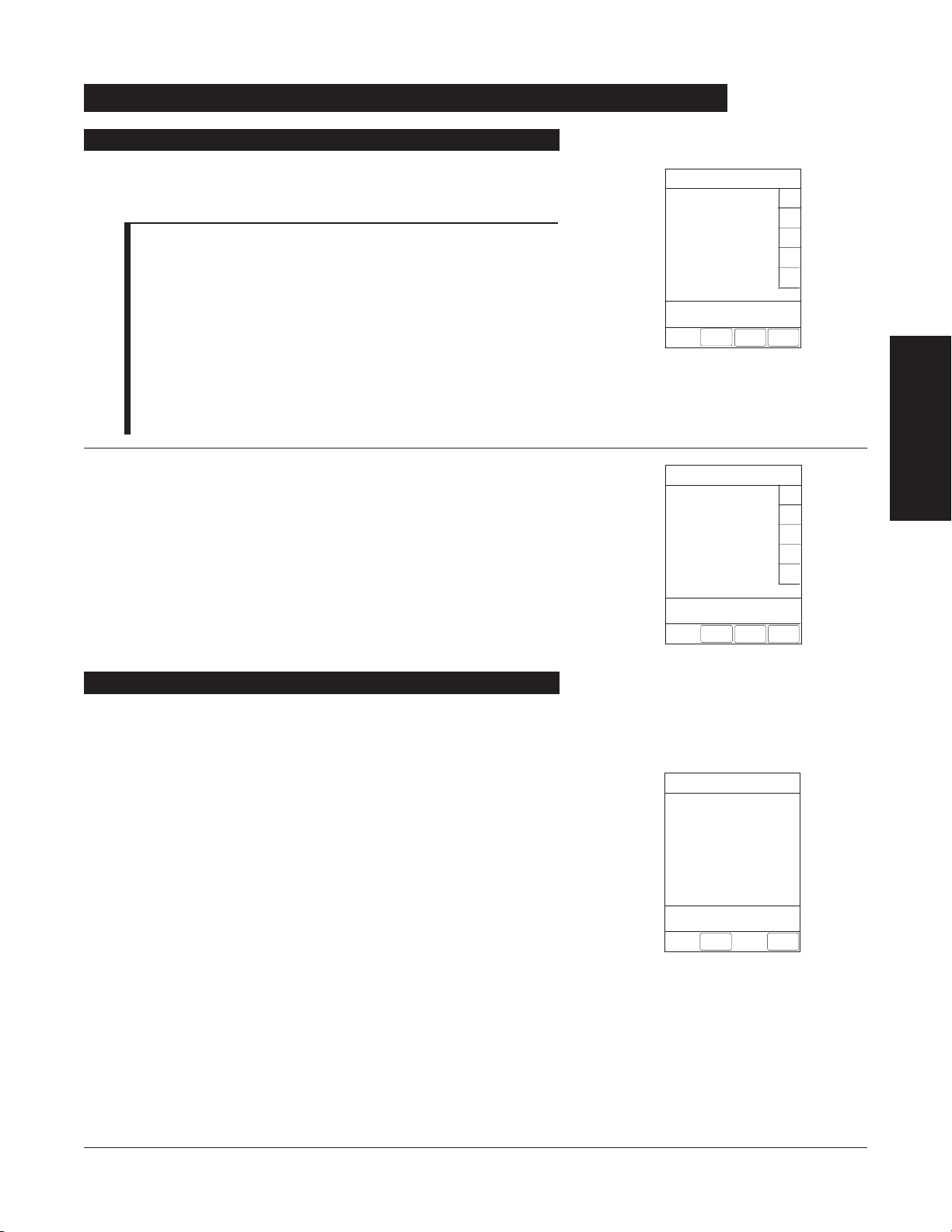
Adding Channel(s) While System is Powered On
IUI Connectors
Title Bar
Channel Status
• A solid channel letter display
indicates channel is operating.
• An outlined channel letter
display indicates channel is
attached and ready for use.
Soft Keys
SYSTEM
ON
Displays
Main Display
Midtown Hospital
Adult ICU
VTBI = 250.0 mL
VOLUME
INFUSED
AUDIO
ADJUST

Channel Selected Indicator
“Inactive” Soft Key
Nonhighlighted indicates a
nonselected soft key.
“Active” Soft Key
Highlighted indicates a selected
soft key.
Prompt Bar
Look here for user prompts.
GETTING STARTED
13
GETTING STARTED
Displays (Continued)
1. Press
OPTIONS
key.
2. Select
DDiissppllaayy CCoonnttrraasstt
soft key.
3. To adjust display for optimum viewing, use
LLiigghhtteerr//DDaarrkkeerr
soft keys.
4. To return to main screen, press
MAIN SSCREEN
soft key.
Adjusting Display Contrast
System Options
>Adjust Display to
Desired Contrast
MAIN
SCREEN
Display Contrast
Lighter
Darker
Medley
™
Medication Safety System
®
>Press START
Infusion Setup
RATE
40
mL/h
_250
mL
PAUSE
SECOND-
ARY
START
VTBI
SYSTEM
ON
Main Display (Continued)
System Options 1 of 3
Display Contrast
Patient ID
Time of Day
Power Down All Channels
Anesthesia Mode
>Select an Option or
EXIT
EXIT
DOWN
PAGE

1. Connect Programming Module to an external
AC power
source.
2. Press
SYSTEM OON
.
3. System self test begins:
• Diagnostics test causes all LED display segments and
Status Indicator lights of attached channel(s) to
illuminate briefly.
• Power Indicator illuminates.
• Appropriate channel identification (
A, B, C or D) displays
on attached channel(s).
• An Audio tone sounds.
• At completion of system-on test,
NNeeww PPaattiieenntt??
screen
appears.
• If
PM Reminder option is enabled and scheduled
preventive maintenance is due,
MAINTENANCE RREMINDER
screen appears.
NOTES:
• Previous infusion parameters are automatically cleared after eight
(
8) hours.
• If any of the following conditions are observed, the Programming
Module or the affected channel must be removed from use and
inspected by qualified personnel:
♦ LED segments are not illuminated during system-on test.
♦ Indicator lights do not illuminate.
♦ Appropriate channel identification (A, B, C or D) is not
displayed.
♦ Audio tone does not sound.
♦ Main Display does not appear backlit, appears irregular, or has
evidence of a row of pixels not functioning properly.
If the affected channel operates normally when it is attached via
an alternate
IUI connector, it may be used until a replacement
channel can be substituted.
14 GETTING STARTED
Start-Up
Powering On System

If the Preventive Maintenance (PM
) Reminder option is enabled
and the Programming Module or an attached module is due for
preventive maintenance, a
MAINTENANCE RREMINDER
message
appears at power up.
NOTES:
• If necessary, the reminder can be temporarily bypassed by
pressing the
CCOONNFFIIRRMM
soft key.
• Notify the appropriate facility personnel when a
MMAAIINNTTEENNAANNCCEE
RREEMMIINNDDEERR
occurs.
1. Remove and, if needed, replace module requiring
maintenance with a new module (reference “Attaching and
Detaching Channels” section).
2. If “system” (Programming Module and attached modules)
was powered off to replace Programming Module, reinitiate
start-up process.
OR
If an “attached module” (such as, a Pump Module) was
powered off and removed,
MAINTENANCE RREMINDER
display
reflects removal of that channel. To continue start–up
process, press
CONFIRM
soft key.
GETTING STARTED
15
GETTING STARTED
Selecting New Patient and Profile Options
Start-Up (Continued)
The option to enter and display a 16-character alphanumeric
patient identifier is always available. The instrument may be
configured to automatically display the
PPaattiieenntt
IIDD
EEnnttrryy
screen
during start up or to provide access only through the
SSyysstteemmss
OOppttiioonnss
menu.
The following procedures assume the Profiles feature is enabled.
NOTE: The display contrast can be adjusted at this time by
pressing the
DISPLAY CCONTRST
soft key and following the directions
on the screen (also see “Displays”, “Adjusting Display Contrast”
section).
Responding to Maintenance Reminder
CONFIRM
B
MAINTENANCE REMINDER
Module(s) due for routine
preventative maintenance:
MAINTENANCE REMINDER
Module(s) due for routine
B
preventative maintenance:
Module A:
CONFIRM
YYYY-MM-DD

1. Select required
NEW PPATIENT?
option.
To indicate programming is for a new patient and clear all
stored patient parameters from memory, press
YYeess
soft key.
OR
To confirm programming is for same patient and retain all
stored patient parameters, press
NNoo
soft key.
• Last used profile displays.
NOTE: If the Profiles feature is disabled, the main menu
appears.
2. Select correct profile.
To accept current profile, press
YYeess
soft key and proceed to
step
5.
• Main screen appears.
OR
To change profile, press
NNoo
soft key and continue with next
step.
• Profile selection screen appears.
3. To select a profile, press corresponding left soft key.
NOTES:
• To view additional choices, press
PPAAGGEE DDOOWWNN
soft key.
• To view system configuration settings for desired profile,
press
View
soft key for that profile.
4. To confirm profile selection, press
CONFIRM
soft key.
• Main screen appears.
5. To enter Patient
ID, if desired, see “Entering Patient ID”
section.
16 GETTING STARTED
Start-Up (Continued)
Patient ID Entry Feature Disabled
Midtown Hospital
Adult ICU
Yes
No
>Select Yes or No
Adult ICU ?
“Yes” Confirms Same
Profile
Selecting New Patient and Profile Options (Continued)
Midtown Hospital
Profiles
>Select a Profile and
Confirm
CONFIRM
PAGE
DOWN
Neonatal
Peds ICU
Neonatal ICU
Adult General Care
Adult ICU
View
1of2
View
View
View
View
Midtown Hospital
NEW PATIENT ?
“Yes” Clears Previous
Patient Data
>Select Yes or No
DISPLAY
CONTRST
Yes
No

1. Select required
NEW PPATIENT?
option.
• To indicate programming is for a new patient and clear
all stored patient parameters from memory:
a. Press
YYeess
soft key.
♦
PPaattiieenntt IIDD EEnnttrryy
screen appears.
b. If patient identifier is not required, press
CONFIRM
soft key.
OR
Enter patient identifier (reference “Entering Patient
ID
” section).
♦ Last used profile displays.
-- OR --
• To confirm programming is for same patient and retain
all stored patient parameters, press
NNoo
soft key.
♦ Last used profile displays.
NOTE: If the Profiles feature is disabled, the main menu
appears.
2. Select correct profile.
To accept current profile, press
YYeess
soft key.
• Main screen appears.
OR
To change profile, press
NNoo
soft key and continue with next
step.
• Profile selection screen appears.
GETTING STARTED
17
GETTING STARTED
Start-Up (Continued)
Selecting New Patient and Profile Options (Continued)
Midtown Hospital
Adult ICU
Yes
No
>Select Yes or No
Adult ICU ?
“Yes” Confirms Same
Profile
Patient ID Entry Feature Enabled
Midtown Hospital
Yes
No
NEW PATIENT ?
>Select Yes or No
“Yes” Clears Previous
Patient Data
DISPLAY
CONTRST
Patient ID Entry
CONFIRM
A-E
F-J
K-O
P-T
U-Y
PAGE
DOWN
A
B
C
D
E
________________
>Enter Patient ID and Press
CONFIRM
EXIT

3. To select a profile, press corresponding left soft key.
NOTES:
• To view additional choices, press
PPAAGGEE DDOOWWNN
soft key.
• To view system configuration settings for desired profile,
press
View
soft key for that profile.
4. To confirm profile selection, press
CONFIRM
soft key.
• Main screen appears.
18 GETTING STARTED
Start-Up (Continued)
Patient ID Entry Feature Enabled (Continued)
Entering Patient ID
Selecting New Patient and Profile Options (Continued)
When the Patient
ID Entry feature is disabled, the
PPaattiieenntt IDEEnnttrryy
screen can only be accessed through the
SSyysstteemmss OOppttiioonnss
menu.
To enter a patient
ID, begin with step 1 of the following
procedure.
When the Patient
ID Entry feature is enabled, the
PPaattiieenntt IDEEnnttrryy
screen appears after responding
YYeess
to
NNeeww PPaattiieenntt??
prompt.
To enter a patient
ID, begin with step 2 of the following
procedure.
1. To access
PPaattiieenntt
ID
EEnnttrryy
screen:
a. Press
OPTIONS
key.
•
SSyysstteemm OOppttiioonnss
menu appears.
b. Press
PPaattiieenntt
ID
soft key.
•
PPaattiieenntt
ID
EEnnttrryy
screen appears.
System Options 1 of 3
>Select an Option or
EXIT
PAGE
DOWN
EXIT
Display Contrast
Time of Day
Power Down All Channels
Anesthesia Mode
Patient ID
Midtown Hospital
Profiles
Adult ICU
Adult General Care
Neonatal
Peds ICU
Neonatal ICU
>Select a Profile and
Confirm
CONFIRM
1of2
View
View
View
View
View
PAGE
DOWN
2. To enter patient identifier, use numeric data entry keys
and/or alpha speed keys.
NOTES:
• An alphanumeric identifier, of up to
16
characters, can be
entered.
• Press the soft key next to a letter group to list letters in that
group. Press the soft key next to an individual letter to
enter that letter.
• To access the letter “
Z” and special characters (hyphen,
underscore, space), press the
PPAAGGEE DDOOWWNN
soft key.
• To clear an entire entry, press
CCLLEEAARR
key.
• To back up a single character at a time, press
CCAANNCCEELL
key.
3. To verify correct entry, press
CONFIRM
soft key.
• If accessed from
NNeeww PPaattiieenntt??
screen, last used profile
appears.
• If accessed from
SSyysstteemmss OOppttiioonnss
menu, main screen
appears.
• Patient
ID appears on main screen, current profile screen,
and
NNeeww PPaattiieenntt??
screen.
GETTING STARTED
19
GETTING STARTED
Entering Patient ID (Continued)
EXIT
A
B
C
D
PAGE
DOWN
>Enter Patient ID and Press
CONFIRM
E
K-O
F-J
P-T
U-Y
A-E
Patient ID Entry
123456789CD_____
CONFIRM
Start-Up (Continued)
Modifying Patient ID
1. Press
OPTIONS
key.
•
SSyysstteemm OOppttiioonnss
menu appears.
2. Press
PPaattiieenntt
ID
soft key.
•
PPaattiieenntt
ID
EEnnttrryy
screen appears.
System Options 1 of 3
>Select an Option or
EXIT
PAGE
DOWN
EXIT
Display Contrast
Time of Day
Power Down All Channels
Anesthesia Mode
Patient ID
Patient ID Entry
CONFIRM
A-E
F-J
K-O
P-T
U-Y
PAGE
DOWN
A
B
C
D
E
________________
>Enter Patient ID and Press
CONFIRM
EXIT

3. To clear entire entry, press
CLEAR
key.
OR
To back up a single character at a time, press
CANCEL
key.
4. To enter modified patient identifier, use numeric data entry
keys and/or alpha speed keys.
NOTES:
• An alphanumeric identifier, of up to
16 characters, can be
entered.
• Press the soft key next to a letter group to list letters in that
group. Press the soft key next to an individual letter to
enter that letter.
• To access the letter “
Z” and special characters (hyphen,
underscore, space), press the
PPAAGGEE DDOOWWNN
soft key.
5. To verify correct entry, press
CONFIRM
soft key.
• Patient
ID Entry verification screen appears.
6. To accept modified Patient ID, press
YYeess
soft key.
• Main screen appears with new Patient
ID.
OR
To retain original (old) Patient
ID, press
NNoo
soft key.
• Main screen appears with old Patient
ID.
20 GETTING STARTED
Start-Up (Continued)
Modifying Patient ID (Continued)
EXIT
A
B
C
D
PAGE
DOWN
>Enter Patient ID and Press
CONFIRM
E
K-O
F-J
P-T
U-Y
A-E
Patient ID Entry
________________
CONFIRM
EXIT
A
B
C
D
PAGE
DOWN
>Enter Patient ID and Press
CONFIRM
E
K-O
F-J
P-T
U-Y
A-E
Patient ID Entry
234567891EF_____
CONFIRM
>Press Yes or No
Patient ID Entry
Yes
No
Patient ID
123456789CD
will be changed to
234567891EF
Is this correct?
Patient ID Entry
A
B
C
D
E
123456789CD
>Enter Patient ID and Press
CONFIRM
EXIT
CONFIRM
PAGE
DOWN
A-E
F-J
K-O
P-T
U-Y
1. Press
AAuuddiioo AAddjjuusstt
soft key.
2. To change volume to desired level, press either
LLoouuddeerr
or
SSoofftteerr
soft key. To sample alarm loudness level,
TTeesstt
soft
key may be pressed.
3. To return to Programming Module screen, press
MAIN
SCREEN
soft key.
• After
30 seconds without a key press, Main Display
appears.
GETTING STARTED
21
GETTING STARTED
1. Press
OPTIONS
key.
2. Press
TTiimmee ooff DDaayy
soft key.
3. Press
CChhaannggee TTiimmee
soft key.
Setting Up Time of Day
Time of Day
System Options
Current time:
__:__
Change
Time
CONFIRM
Adjusting Audio Volume
Louder
>Change Setting or
Cancel
Audio Volume Adjust
Test
Softer
MAIN
SCREEN
3
VTBI = 250.0 mL
VOLUME
INFUSED
AUDIO
ADJUST
Midtown Hospital
Adult ICU
System Options
Time of Day
Current time:
09:00
CONFIRM
Change
Time

22 GETTING STARTED
4. Enter current Time of Day.
5. Press
CCoonnffiirrmm
soft key.
NOTE: The format is a 24-hour clock (military time).
1. Press
OPTIONS
key.
2. Press
PAGE DDOWN
soft key.
3. Press
SSyysstteemm CCoonnffiigguurraattiioonn
soft key.
4. Select
PPrrooggrraammmmiinngg MMoodduullee
.
5. To review various system configuration settings, press
PAGE
UP
and
PAGE DDOWN
soft keys.
6. To return to main screen, press
CANCEL
key or
EXIT
soft key.
Reviewing System Configuration
Factory Default:
Yes
System Config - Module 1 of 2
Programming Module
Pump Module
SPO2 Module
>Press CANCEL or EXIT
EXIT
Shared Infusion Settings
PAGE
DOWN
Setting Up Time of Day (Continued)
>Press CANCEL or EXIT
PAGE
DOWN
EXIT
System Config - PM 1 of 2
Alarm Audio:
Profile 1
Battery Meter:
Disabled
Clock Setup:
09:00
Dose Checking: ALWAYS
Anesthesia Mode:
Disabled
EXIT
PAGE
UP
System Config - PM 2 of 2
Max Pt. weight:
100 kg
Profiles:
Disabled
Disabled
Enabled
Tamper resist:
PM reminder:
Enabled
Patient ID Entry:
>Press CANCEL or EXIT
System Options
Time of Day
Current time:
14:30
CONFIRM
Change
Time

1. Press
OPTIONS
key.
2. Press
PPaaggee DDoowwnn
soft key.
3. Press
SSeerriiaall NNuummbbeerrss
soft key.
• Serial numbers for Programming Module and all
attached modules display.
NOTE: “nnnn-nnnnnnnn” in the illustrated display
represents a serial number.
4. To return to main screen, press
EXIT
soft key.
GETTING STARTED
23
GETTING STARTED
Reviewing Serial Number
System Options 2 of 3
PAGE
UP
Guardrails Event Counter
System Configuration
>Select an Option or
EXIT
EXIT
Software Versions
Serial Numbers
Battery Runtime
PAGE
DOWN
System Options 1 of 3
>Select an Option or
EXIT
PAGE
DOWN
EXIT
Display Contrast
Time of Day
Power Down All Channels
Anesthesia Mode
Patient ID
PM:
>Press CANCEL or EXIT

1. Press
OPTIONS
key.
2. Press
PAGE DDOWN
soft key.
3. Press
SSooffttwwaarree VVeerrssiioonnss
soft key.
4. To review software version information, press
VViieeww
soft key
next to desired channel.
OR
To return to main screen, press
EXIT
soft key
5. To return to previous screen, press
EXIT
soft key.
NOTE: “nn.nn” in the illustrated display represents a software
version.
24 GETTING STARTED
Reviewing Software Version
Software Rev. Review
APM:
Module A:
Module B:
Module C:
Module D:
View
View
View
View
View
>Select an Option or
EXIT
EXIT
EXIT
>Press CANCEL or EXIT
Software Rev. Review
Module Software: A
Main processor:
nn.nn
nn.nn
nn.nn
Main boot block:
Keyboard:
System Options 1 of 3
>Select an Option or
EXIT
PAGE
DOWN
EXIT
Display Contrast
Time of Day
Power Down All Channels
Anesthesia Mode
Patient ID
System Options 2 of 3
Battery Runtime
System Configuration
Serial Numbers
Software Versions
Guardrails Event Counter
>Select an Option or
EXIT
PAGE
EXIT
UP
PAGE
DOWN

1. Press
OPTIONS
key.
2. Press
PAGE DDOWN
soft key.
3. Press
GGuuaarrddrraaiillss EEvveenntt CCoouunntteerr
soft key.
4. To clear
event counter information, press
CLEAR
key and
then
EXIT
soft key.
OR
To retain
event counter information and return to main
screen, press
EXIT
soft key.
GETTING STARTED
25
GETTING STARTED
1. Press
OPTIONS
key.
2. Press
PPoowweerr DDoowwnn AAllll CChhaannnneellss
soft key.
3. Press
YYeess
soft key.
• During power off sequence, Main Display flashes
POWERING DDOWN
.
Powering Off
Powering Off System
System Options 1 of 3
>Select an Option or
EXIT
PAGE
DOWN
EXIT
Display Contrast
Time of Day
Power Down All Channels
Anesthesia Mode
Patient ID
Viewing and Clearing Guardrails®Event Counter
System Options 2 of 3
PAGE
UP
Guardrails Event Counter
System Configuration
>Select an Option or
EXIT
EXIT
Software Versions
Serial Numbers
Battery Runtime
PAGE
DOWN
System Options
Power Down
All Channels?
>Press Yes or No
Yes
No
Press and hold
CHANNEL OOFF
key until a beep is heard
(approximately
1.5 seconds) and then release to initiate power
down.
NOTE: To interrupt the power down sequence, quickly press any
one of the numeric keys on the Programming Module.
• During power off sequence, Main Display flashes
PPoowweerriinngg
DDoowwnn
.
• Once all attached channels are powered off, Programming
Module automatically powers down.
26 GETTING STARTED
1. Initiate operation of desired channels.
2. Press and hold Tamper Resist Switch, on back of
Programming Module, for three to four seconds. An
advisory tone and a three-second
PANEL LLOCKED
prompt on
Main Display confirm activation. When Tamper Resist is
active, keypad panel is locked; however, clinician may:
• Silence key for audio alarm.
• View volume(s) infused.
• View and test audio alarm setting.
• View selected parameters on SpO
2
Module.
Any other key press will result in a visual
PANEL LLOCKED
prompt and, if
KKeeyy CClliicckk AAuuddiioo
is enabled, an illegal
key–press audio advisory.
3. To unlock keypad panel, press and hold Tamper Resist
Switch for three to four seconds. A three-second
PANEL
UNLOCKED
prompt on Main Display and, if
KKeeyy CClliicckk AAuuddiioo
is enabled, an advisory tone confirms Tamper Resist is off.
Locking/Unlocking Tamper Resist
PANEL UNLOCKED
VTBI = 250.0 mL
VOLUME
INFUSED
AUDIO
ADJUST
Midtown Hospital
Adult ICU
Powering Off Channel
Powering Down
Powering Off (Continued)
Midtown Hospital
Adult ICU
VTBI = 250.0 mL
PANEL LOCKED
VOLUME
INFUSED
AUDIO
ADJUST

GETTING STARTED 27
GETTING STARTED
The optional Computer Link feature allows a hospital computer
to interact with the instrument. The computer cannot start or
stop the instrument, set the rate, or make any change in status.
If the feature is off, the computer cannot communicate with the
instrument.
The Computer Link option is available in the Maintenance Mode.
The computer interface uses a three wire RS-232 signal definition
through an
RJ45 type connector. The table to the right shows
the pin definition. Do not connect anything to the unused
pins.
Qualified service personnel can turn the Computer Link feature
on or off.
NOTE: To assure continued electromagnetic compatibility
performance, the communications cable which attaches to the
instrument should be a category 5 type cable, no longer than
3 meters.
Pin NNumber
4
5
7
Description
Ground
RS-232 TxD (Out of
Programming Module)
RS-232 RxD (Into
Programming Module)
Computer Link
Only systems that have been tested
and certified in compliance to
IEC 601–1/EN 60601–1 standard
should be connected to the Medley™
System Computer/ Connections port.
CAUTION
Use of accessories or cables other
than those specified may result in
degraded electromagnetic
compatibility performance of this
device.
CAUTION

28 GETTING STARTED
THIS PAGE
INTENTIONALLY
LEFT BLANK

Advisory A sequence of audio and/or visual signals indicating the operating status
of the Medley™ Medication Safety System. The audio may be silenced
for approximately two minutes by pressing the
SILENCE
key.
Alarm An audio and visual signal that a potentially unsafe condition is present.
Immediate action is required. The audio may be silenced for
approximately two minutes by pressing the
SILENCE
key.
Error An audio and/or visual signal that a failure has been detected.
Immediate action is required.
Guardrails
®
Alert A visual message to help reduce programming errors by indicating a
Guardrails
®
Limit (“soft” or “hard”) has been exceeded. A response is
required before programming can continue.
Guardrails
®
Clinical Advisory A visual message when a designated drug is selected, to remind clinician
of specific hospital standards of practice when programming an
IV
medication. A specific clinical advisory can be associated with a selected
drug within any of the patient care profiles.
Maintenance Reminder A visual message that, when enabled, appears at module startup when
scheduled preventive maintenance is due/overdue for any part of the
Medley™ System (Programming Module or attached module).
Prompt A visual message, appearing on the bottom line of the Main Display or in
the Channel Message Display. The message may be accompanied by an
audio signal that can be silenced for twelve seconds by pressing the
SILENCE
key.
To enhance safety and ease of operation, the Medley™ System provides a full range of audio and visual
alarms, errors, and messages.
ALARMS, ERRORS, MESSAGES
ALARMS, ERRORS, MESSAGES 29
ALARMS, ERRORS,
MESSAGES
Definitions

Advisory
Alarm
Error (Hardware Detected)
Error (Software Detected)
Illegal Key Press
Key Click
Prompt
SpO
2
Alarm
Switchover
One short beep every two seconds
Choice of three alarm audio profiles,
selectable in System Configuration
Pairs of long beeps
Pairs of long beeps
Two short beeps
One short beep
One short beep every two seconds
Unique alarm pattern.
Six short beeps: secondary switching
to primary. Two short beeps: bolus
switching to continuous.
Variable volume; can be silenced for
two minutes.
Variable volume; can be silenced for
two minutes.
Fixed maximum decibel volume;
cannot be silenced.
Fixed maximum decibel volume; can
be silenced for two minutes.
Variable volume; cannot be silenced.
Fixed minimum volume; can be
silenced and disabled in System
Configuration.
Variable volume; can be silenced.
Different sound than other alarms.
Variable volume; can be silenced and
disabled in System Configuration.
30 ALARMS, ERRORS, MESSAGES
Audio Characteristics
The Programming Module and Main Display provide various types of alert information. The characteristics
of the accompanying audio sounds are as follows:
Type Sound Notes

Battery Discharged
Channel Disconnected
Very Low Battery <5 minutes to
system shutdown
Operation of all channels stopped
due to insufficient battery charge.
Channel(s) disconnected while in
operation or have a communication
problem.
Battery has five minutes or less of
power at current power
consumption rate before operation
stops.
Connect AC power cord to power
source; alarm will be silenced. Press
RESTART key on Pump Module to
continue operation of paused
channels.
To silence alarm and clear message
from screen, press
CONFIRM soft key.
Reattach module, if desired,
ensuring it is securely “clicked” into
place at Channel Release Latch. If
alarm is still present, replace channel
with an operational instrument.
Connect AC power cord to power
source; alarm will be silenced.
ALARMS, ERRORS, MESSAGES 31
ALARMS, ERRORS,
MESSAGES
Alarms
Alarm Meaning Response

Channel Error
Defective Battery
Hardware Detected Error
Missing Battery
Power Supply Error
System Error
Error detected. Operation stops on
affected channel.
Defective battery detected.
Error detected on Programming
Module. Operation stops on all
channels.
Battery detected as not present or
not connected.
Power supply system malfunction
detected.
Error detected on Programming
Module. Operation continues on all
channels.
To silence alarm and continue
operation of unaffected channels,
press
CONFIRM soft key . Replace
channel with an operational
instrument, as required. Service by
qualified personnel is required.
To power down system, press
SYSTEM OFF soft key; or to continue
temporary operation while an
operational Programming Module
can be located, press
SILENCE key.
Service by qualified personnel is
required.
Press
SYSTEM ON key to power down
system. Replace Programming
Module with an operational system.
Service by qualified personnel is
required.
To power down system, press
SYSTEM OFF soft key; or to continue
temporary operation while an
operational Programming Module
can be located, press
SILENCE key.
Service by qualified personnel is
required.
Disconnect AC power immediately.
To power down system, press
SYSTEM OFF soft key; or to continue
operation under battery power while
an operational Programming
Module can be located, press
SILENCE key. Service by qualified
personnel is required.
To power down system, press
SYSTEM OFF soft key; or to continue
temporary operation while an
operational Programming Module
can be located, press
SILENCE key.
Service by qualified personnel is
required.
32 ALARMS, ERRORS, MESSAGES
Errors
Error Meaning Response

Battery Run Time = X.X hours
Low Battery
Panel Locked
Panel Unlocked
Powering Down
Replace Battery
AC power cord is disconnected from
power source. Approximate
remaining battery run time under
current power consumption rate is
displayed.
Low battery threshold sensed;
remaining battery run time is
limited.
Tamper Resist feature is active and
key was pressed.
Tamper Resist feature deactivated.
Last channel powering off. System
shuts off in indicated number of
seconds.
Occurs at System On. Battery has
less than 50% of original capacity.
None. Connect AC power cord to
power source as soon as possible.
Connect AC power cord to power
source; alarm will be silenced.
If appropriate, deactivate Tamper
Resist feature using Tamper Resist
Control on back of Programming
Module.
None.
Press any key, except
SYSTEM ON key,
to cancel power down sequence.
Press either
SYSTEM OFF or CONFIRM
soft key to continue normal
operation with reduced battery
capacity. Service by qualified
personnel is required.
ALARMS, ERRORS, MESSAGES 33
ALARMS, ERRORS,
MESSAGES
Messages
Message Meaning Response

THIS PAGE
INTENTIONALLY
LEFT BLANK
34 ALARMS, ERRORS, MESSAGES

Battery OOperation
: Battery run time is a function of the number of channels attached and channel activity.
With a new, fully charged battery, the system will operate as follows before a "
BATTERY
DISCHARGED
" message occurs:
• 8 hours with 1 Pump Module infusing at 25 mL/h
• 4 hours with 4 Pump Modules infusing at 25 mL/h
• 6 hours with 1 active SpO
2
Module
• 8 hours with 1 Syringe Module infusing at 5 mL/h
• 4 hours with 4 Syringe Modules infusing at 5 mL/h
Communication DData PPort
: RS-232 with a RJ45 connector.
Dimensions
: 6.9"W x 8.8"H x 9"D (including pole clamp)
Electric CClassification
: Class 1, Internally Powered Equipment
NOTE: Refer to module specific Directions for Use for shock protection type and
defibrillation-proof rating information.
Electronic MMemory
: System configuration parameters stored in volatile memory will be retained for at least 6
months by the internal backup lithium battery. Additionally, channel specific parameters
are stored for 8 hours by the Programming Module and then automatically purged by
the system.
Environmental CConditions
: Operating
Storage/Transport
Temperature Range: 41 to 104°F -4 to 140°F
(5 to 40°C) (-20 to 60°C)
Relative Humidity: 20 to 90% 5 to 85%
(Avoid prolonged exposure Noncondensing Noncondensing
to relative humidity >85%)
Atmospheric Pressure: 525 to 4560 mmHg 375 to 760 mmHg
(700 to 6080 hPa) (500 to 1013 hPa)
Equipment OOrientation
: To ensure proper operation, the instrument must remain in an upright position.
Fluid IIngress PProtection
: IPX1, Drip Proof
Leakage CCurrent
: Less than 100 microamps
Power RRequirements
: 100 - 240V ~, 50/60 Hz, 150 VA MAX (See Notes 1 and 2)
Weight
: 7.2 lbs
The Medley™ System Technical Service Manual is available from
ALARIS Medical Systems. It includes
routine service schedules, interconnect diagrams, component parts lists and descriptions, test procedures,
and other technical information, to assist qualified service personnel in repair and maintenance of the
instrument’s repairable components. Maintenance procedures are intended to be performed only by
qualified personnel, using the service manual and Medley™ Maintenance Software.
MAINTENANCE
35
MAINTENANCE
MAINTENANCE
Specifications

NOTES:
1. Power Cords; North America:
To ensure correct polarity and grounding reliability, use power cords that incorporate a NEMA 5-15P (125V) or
NEMA 6-15P (250V) plug only.
2. Power Cords; International:
Use only cords that comply with IEC 60245, or IEC 60227, designation #53 and local electrical codes and/or
regulations.
3. Compliance to Standards:
The Medley™ Medication Safety System has been assessed and complies with the following standards:
UL 2601–1, including A1 and A2; CSA C22.2 No. 601.1, including A1 and A2; IEC/EN 60601–2–24;
IEC/EN 60601–1–2 and AAMI ID26.
36 MAINTENANCE36 MAINTENANCE
Specifications (Continued)
System Configurable Settings
Profile 1, 2 or 3
Enabled - Disabled
Enabled - Disabled
Set date and time
Always, Smart (only with
Profiles feature)
Enabled - Disabled
0.1 - 500 kg
Enabled - Disabled
Enabled - Disabled
Enabled - Disabled
Enabled - Disabled
Feature
Alarm Audio Profile
Anesthesia Mode
Battery Meter Display
Clock Setup (Date and Time)
Dose Checking
Key Click Audio
Max Patient Weight
Patient ID Entry
Preventive Maintenance (PM)
Reminder
Profiles
Tamper Resist
Default Setting Options
Profile 1
Disabled
Disabled
N/A
Always
Enabled
500 kg
Disabled
Enabled
Disabled
Disabled
If the configuration settings need to be changed from the
"Factory Default" settings, refer to the applicable Technical
Service Manual or contact
ALARIS Medical Systems, Technical
Support, for technical, troubleshooting, and preventive
maintenance information.
NOTE: With the Profiles feature enabled, the settings are
configured independently for each profile. A hospital-defined,
best-practice data set must be uploaded to enable the Profiles
feature. Date and Time is a system setting and is the same in all
profiles.

The Medley™ Programming Module is equipped with a 12 volt,
4200
mAh nickel metal hydride battery. The battery is charging
whenever the instrument is plugged into an
AC receptacle. The
life expectancy of the battery is dependent on the amount of
use, the depth of discharge, and the state of the charge that is
maintained. Generally, the battery will have the longest life
(recommended replacement =
2 years) if the instrument is
plugged in and battery use is infrequent. Frequent use of
battery power and insufficient battery charge cycles will
significantly decrease the life of the battery.
The quality of the battery is also a significant factor in
determining battery life and runtime. The battery cannot be
repaired and should not be opened. Replace the battery with
the same type, size and voltage rating. Use of any other brand
may yield poor performance and is not recommended.
Batteries should be charged in a room with a temperature
between
50 - 80.6
°F (
10 - 27°C), to minimize charge time and
maximize battery life.
Plug the Programming Module into an
AC outlet during storage,
to ensure a fully charged battery when needed.
(
AC indicator light) will be on whenever the Programming
Module is plugged in.
MAINTENANCE 37
MAINTENANCE
Battery Care and Maintenance
Battery Type and Charging
Storage
Battery Charge
• The Medley™ Programming Module is shipped with the
battery in a discharged condition.
• Before the Programming Module is released for use, it should
be plugged into a hospital grade
AC outlet and the battery
charged for at least eight hours. This will ensure proper
battery operation when the Medley™ System is first set up for
patient use.
• Whenever possible, leave the power cord connected to an
external
AC power source while operating the instrument.

The battery capacity should be checked at least once every six
months. Refer to the Medley™ System Technical Service Manual
for test and replacement procedures.
If the Programming Module is to be stored at temperatures in
excess of
86°F
(30°C) for one or more months, the battery should
be removed and placed in an environment of
50
– 86°F
(10 – 30
°C).
If the batteries are to be stored for more than one year, they
should be charged at least once per year to prevent leakage and
deterioration in performance due to self-discharge.
When the battery is first being put into use, or has been out of
use for one or more months, it will not have full capacity due to
deactivation of reactants.
Restore such batteries to original performance by repeating one
or two cycles of fully charging and fully discharging.
Some temporary reduction in capacity might become apparent if
the battery is partially discharged repeatedly. Doing one or two
cycles of full discharge and full charge can restore full
performance.
38 MAINTENANCE38 MAINTENANCE
Battery Care and Maintenance (Continued)
Battery Care
Battery Cautions and Disposal
Battery replacement should be performed by qualified service
personnel while the instrument is not in use.
DO NOT open, incinerate or short
circuit. Worn–out batteries must be
disposed of properly, according to
local regulations.
CAUTION

DO NOT spray cleaning fluids directly onto the instrument or
immerse the instrument in fluids.
DO NOT use solutions containing phosphoric acid (Foamy
Q&A*), aromatic solvents (naphtha, paint thinner,
etc.), chlorinated solvents* (Trichloroethane,
MEK,
Toluene, etc.), ammonia, acetone, benzene, xylene or
alcohol, other than as specified below.
DO NOT use hard or pointed objects to clean any part of the
instrument.
Acceptable cleaning solutions are:
Warm water
Mild detergent (
such as, Manu-Klenz)
10% bleach solution (1 part bleach to 9 parts water)
Compublend II
Envirocide
2% Glutaraldehyde in water
Hydrogen Peroxide
3%
70%
Isopropyl Alcohol
2%
Phenols in water (O-Syl 1:128, Pheno-Cen 1:256, Vesphene
)
10%
Providone Iodine (Betadine)
Quaternaries
1:512
WEX-CIDE
NOTE: All recommended solutions must be diluted per the
Manufacturer’s recommendation.
1. Keep instrument upright and do not allow any part of
instrument to become saturated with or submersed in fluid
during cleaning operation.
2. Use a soft cloth dampened with warm water and a mild
nonabrasive cleaning solution to clean all exposed surfaces.
For sanitizing or antibacterial treatment, use 10% bleach
solution and water.
NOTE: A soft-bristled brush may be used to clean hard to
reach and narrow areas.
3. Use a soft cloth dampened with water to rinse off cleaning
solution.
* Excluding 10% bleach solution in water.
MAINTENANCE 39
MAINTENANCE
Cleaning
Turn the instrument off and unplug
the power cord from the
AC power
source before cleaning. Do not spray
fluids directly onto the rear case of
the instrument. Do not steam
autoclave, EtO sterilize, immerse the
instrument or allow fluids to enter
the instrument case. Failure to follow
these instructions may result in an
electrical hazard.
WARNING
The solutions/solvents identified as
NOT
to be used can damage the
surfaces of the instrument.
CAUTION

To ensure the system remains in good operating condition, both
regular and periodic inspections are required.
RReegguullaarr iinnssppeeccttiioonnss
consist of a visual inspection for damage
and cleanliness, and performing the procedure described in the
“Start-Up” section of this Directions for Use before each usage
of the instrument. Regular inspections must be performed by
the hospital/facility and if any damage is found, service is
required.
RREEGGUULLAARR IINNSSPPEECCTTIIOONNSS
PROCEDURE FREQUENCY
INSPECT FOR DAMAGE:
Exterior Surface Each usage
Pole Clamp Each usage
Power Cord Each usage
Keypad Each usage
CLEANING As required
Start-Up Each usage
1. Exterior Surfaces - examine for overall condition and verify:
• No damage, cracks or deformities.
• Case is clean and free from
IV solution residue.
• Labels and markings are legible.
• No tape or other foreign material is on sides of case;
anything of this nature could prevent proper latching of
channels.
•
IUI
Connectors have not been damaged.
2. Pole Clamp
Pole Clamp should be secure and functioning.
3. Power Cord Assembly - examine for:
• Signs of damage, cuts or deformities in cord. If
damaged, replace entire cord.
• Integrity of hospital-grade power plug. Attempt to
wiggle blades, to verify they are secure. If any damage is
suspected, replace entire cord.
4. Keypad
Check membrane switches for damage.
PPeerriiooddiicc iinnssppeeccttiioonnss
of the hardware are required. For detailed
instructions on performing periodic inspections and
maintenance, refer to the Medley™ Medication Safety System
Technical Service Manual and supplemental service bulletins, and
Medley™ Maintenance Software User Manual.
40 MAINTENANCE40 MAINTENANCE
Inspection Requirements
Failure to perform these inspections
may result in improper instrument
operation.
WARNING
Periodic inspections should only be
performed by qualified service
personnel.
CAUTION

Customer Service
Information or assistance may be obtained by calling one of the
following Customer Service numbers:
United States:
Canada:
(800) 482-4822
(800) 387-8309
NOTE: If the instrument shows evidence of damage in transit,
notify the carrier’s agent immediately. Do not return damaged
equipment to the factory before the carrier’s agent has authorized
repairs.
If the instrument fails to respond as described in this document
and the cause cannot be determined, do not use the instrument.
Contact qualified
ALARIS
Medical Systems service personnel.
MAINTENANCE 41
MAINTENANCE
Service Information
Technical support, service information, applications, and
manuals may be obtained by contacting an ALARIS Medical
Systems representative.
United States:
Canada:
Eastern
Western
When submitting any request for service, include:
• Model number
• a description of difficulty experienced
• instrument settings
• administration set/lot number
• solution(s) used
• message displayed at time of difficulty
Instruments returned from the service
depot to your facility may be set to
factory defaults and not have a
hospital-defined data set loaded.
Biomedical personnel in the facility
are responsible for checking-in the
instrument and ensuring the current
hospital-approved data set is loaded.
WARNING
(800) 854-7128, extension 6003
(800) 908-9918
(800) 908-9919
Technical Support
Product Return
If it is necessary to return the instrument for service, obtain a
return authorization number prior to shipment. Carefully
package the instrument (preferably in the original packaging),
reference the return authorization information, and return it to
the appropriate service or distribution center.
ALARIS Medical
Systems does not assume any responsibility for loss of, or
damage to, returned instruments while in transit.

ALARIS Medical Systems, Inc., (hereinafter referred to as “ALARIS Medical Systems”) warrants that:
A. Each new
ALARIS
Medical Systems
®
Medley™ Programming Module is free from defects in material
and workmanship under normal use and service for a period of one (
1) year from the date of
delivery by
ALARIS Medical Systems to the original purchaser.
B. The battery and each new accessory is free from defects in material and workmanship under
normal use and service for a period of ninety (
90) days from the date of delivery by ALARIS Medical
Systems to the original purchaser.
If any product requires service during the applicable warranty period, the purchaser should
communicate directly with the relevant account representative to determine the appropriate repair
facility. Except as provided otherwise in this warranty, repair or replacement will be carried out at
ALARIS Medical Systems’ expense. The product requiring service should be returned promptly,
properly packaged and postage prepaid by purchaser. Loss or damage in return shipment to the
repair facility shall be at purchaser’s risk.
In no event shall ALARIS Medical Systems be liable for any incidental, indirect or consequential
damages in connection with the purchase or use of any
ALARIS Medical Systems
®
Product. This
warranty shall apply solely to the original purchaser. This warranty shall not apply to any subsequent
owner or holder of the product. Furthermore, this warranty shall not apply to, and
ALARIS
Medical
Systems shall not be responsible for, any loss or damage arising in connection with the purchase or
use of any
ALARIS Medical Systems
®
Product which has been:
(a) repaired by anyone other than an authorized
ALARIS Medical Systems Service Representative;
(b) altered in any way so as to affect, in
ALARIS Medical Systems’ judgment, the product’s stability or
reliability;
(c) subjected to misuse or negligence or accident, or which has had the product’s serial or lot number
altered, effaced or removed;
or
(d) improperly maintained or used in any manner other than in accordance with the written
instructions furnished by
ALARIS Medical Systems.
This warranty is in lieu of all other warranties, express or implied, and of all other obligations or
liabilities of
ALARIS Medical Systems, and ALARIS Medical Systems does not give or grant, directly or
indirectly, the authority to any representative or other person to assume on behalf of
ALARIS Medical
Systems any other liability in connection with the sale or use of
ALARIS Medical Systems
®
Products.
ALARIS MEDICAL SYSTEMS DISCLAIMS ALL OTHER WARRANTIES, EXPRESS OR IMPLIED, INCLUDING ANY WARRANTY
OF MERCHANTABILITY OR OF FITNESS FOR A PARTICULAR PURPOSE OR APPLICATION.
See packing inserts for international warranty, if applicable.
42 MAINTENANCE42 MAINTENANCE
WARRANTY


ALARIS®, ALARIS Medical Systems®, Flo-Stop®, Guardrails®, and Medley™ are trademarks and registered trademarks of ALARIS Medical Systems, Inc.
All other trademarks belong to their respective owners.
US Pat. Nos. 5,601,445; 5,713,856; 5,781,442; 5,800,387; 5,836,910; 5,941,846; AU Patent Nos. 693,662; 703,178; 703,203; 719,254; 728,366;
AT 0,225,158; BE Brevet Belge No. 0,225,158; CA Patented/Breveté 1,258,212; 2,026,518; CH +0,225,158; DE D.B.P. No. P3686558.3;
FR Brevet No. 0,225,158; GB Patent No. 0,225,158; IT Brevettato Vol. R.A. No. 0,225,158; JP Patent No. 1,816,872 ;
NL Ned. Octrooi No. 0,225,158; SE Sv. pat. nr 0,225,158; TW Patent No. NI–107963. Other Patents Pending
147026-006 Copyright© 2003 ALARIS Medical Systems, Inc. All Rights Reserved
ALARIS Medical Systems, Inc.
10221 Wateridge Circle
San Diego, California 92121 U.S.A.
Mail:
P.O. Box 85335
San Diego, California 92186-5335 U.S.A.
 Loading...