

Page 1
EN
SMI2_2016.05_0113_EN
SMI2
RS485 Display
User guide
akYtec GmbH · Vahrenwalder Str. 269 A · 30179 Hannover · Germany · Tel.: +49 (0) 511 16 59 672-0 · www.akytec.de
Page 2

1
Contents
1
Safety guidelines ............................................................................................................................................ 2
2 Intended use ................................................................................................................................................... 3
3 Specification ................................................................................................................................................... 4
4 Functional description ................................................................................................................................... 5
5 Installation and commissioning .................................................................................................................... 6
5.1 Installation ................................................................................................................................................ 6
5.2 Programming ........................................................................................................................................... 6
5.3 Configuration ........................................................................................................................................... 6
5.4 Configuration check ................................................................................................................................. 7
5.5 “Factory settings” mode ........................................................................................................................... 7
6 Operation ......................................................................................................................................................... 8
6.1 Slave mode .............................................................................................................................................. 8
6.2 Master mode ............................................................................................................................................ 8
6.3 Operating parameters .............................................................................................................................. 8
6.4 Alarm logic ............................................................................................................................................... 8
6.5 Error display ............................................................................................................................................. 9
7 Maintenance .................................................................................................................................................. 10
8 Transportation and storage ......................................................................................................................... 11
9 Scope of delivery .......................................................................................................................................... 12
Appendix A Dimensions ................................................................................................................................... 13
Appendix B Electrical connection ................................................................................................................... 14
Appendix C Communication protocol ............................................................................................................. 15
Appendix D Functions and data transfer ........................................................................................................ 16
akYtec GmbH · Vahrenwalder Str. 269 A · 30179 Hannover · Germany · Tel.: +49 (0) 511 16 59 672-0 · www.akytec.de
Page 3

2
Safety guidelines
1 Safety guidelines
Please read through the user guide carefully before commissioning the device. Damages that arise from
non-observance of the guidelines in the user guide shall be devoid of any liability.
– The device may only be used in the manner described in this user guide.
– No technical modifications may be made to the device.
– The device may not be used if the environmental conditions (temperature, humidity etc.) are not within
the limits indicated in the specification.
– The device may not be used in explosive areas and there may be no chemically active substances in the
atmosphere.
– The device should only be cleaned with a damp cloth. No abrasives or solvent-based cleaners should be
used.
Non-observance of the safety guidelines may result in damage to the device and injury to users
.
akYtec GmbH · Vahrenwalder Str. 269 A · 30179 Hannover · Germany · Tel.: +49 (0) 511 16 59 672-0 · www.akytec.de
Page 4

3
Intended use
2 Intended use
The device is intended for use in a RS485 network and supports the protocols Modbus RTU, Modbus ASCII
and akYtec. It can operate either as a slave or a master.
The field of application of the device includes the control and monitoring of industrial processes. The device
can be used in automated systems as a primary or secondary display.
The device may only be operated
– properly installed and
– in accordance with the specification.
Improper use
– The SMI2 may not be used for medical devices that sustain, monitor or otherwise affect human life
or health.
– The device may not be used in potentially explosive environment.
– The device may not be used in an atmosphere with chemically active agents.
akYtec GmbH · Vahrenwalder Str. 269 A · 30179 Hannover · Germany · Tel.: +49 (0) 511 16 59 672-0 · www.akytec.de
Page 5
4
Power supply
12 / 24 (10.5…30) V DC
Power consumption, max.
1.5 W
Protocol
Modbus RTU/ASCII, akYtec
Interface
RS485 (2-wire bus)
Baud rate
2.4…115.2 kBit/s
Display
LED, 7-segment display, 4-digit
Character height
14 mm
Display colour
red
IP Code
front IP65, rear IP20
Dimensions
48 x 26 x 65 mm
Weight
approx. 30 g
Protection class
III
Ambient temperature
-25…+55 °C
Storage temperature
-40…+70 °C
Humidity
up to 80% (non-condensing)
Galvanic isolation
yes
Specification
3 Specification
Table 3.1 Specification
akYtec GmbH · Vahrenwalder Str. 269 A · 30179 Hannover · Germany · Tel.: +49 (0) 511 16 59 672-0 · www.akytec.de
Page 6
5
PS
Display
SMI2
Converter
TTL
↔RS485
Micro-
8 8 8 8
RESET
RS485
controller
10.5...30 V DC
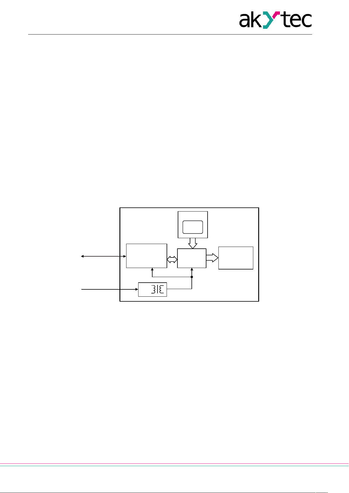
Functional description
4 Functional description
A 4-digit, 7-segment LED display (red) with 14 mm character height displays data received from the RS485
network, error messages and/or configuration parameters of the device.
The secondary voltage source with galvanic isolation guarantees a stable power supply to the device and
offers protection against polarity reversal.
The RESET button is positioned on the cylindrical surface of the device. The button enables to retrieve the
configuration parameters and to restore factory settings, if necessary.
The device has the following functions:
– receiving data from a master device in the slave mode
– querying data from a slave device in the master mode
– processing received data according to the set parameters
– displaying transmitted value
– displaying transmitted value of a type Int or Word with the set number of decimal points
– optional flashing function
– displaying errors if the data transfer is faulty or the received value cannot be displayed (see 6.5)
– displaying configuration parameters of the device
– modifying configuration parameters according to data received from the master
PS – Power supply
Fig. 1 Block diagram
akYtec GmbH · Vahrenwalder Str. 269 A · 30179 Hannover · Germany · Tel.: +49 (0) 511 16 59 672-0 · www.akytec.de
Page 7
6
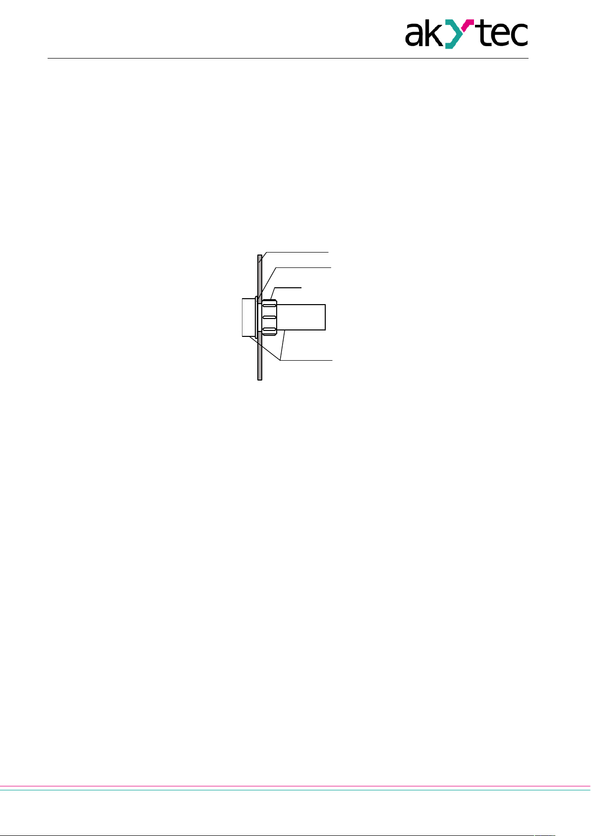
Switch panel
Gasket
Nut
Enclosure
Installation and commissioning
5 Installation and commissioning
5.1 Installation
The SMI2 is designed for switch panel mounting in a borehole of Ø22.5 mm (see Appendix A for dimensions).
Carefully position the supplied gasket on the display rear surface. Insert the cylindrical part of the device into
the borehole and tighten the nut from the rear side of the switch panel. Connect the device to the auxiliary
voltage and signal cables in accordance with Appendix B.
The factory settings can be changed before assembly if necessary (see Appendix D.3). For this purpose the
device must be connected to the RS485 interface of the programming device (PC) and to the auxiliary power
supply. For further details see 5.3.
Fig. 2 Mounting
5.2 Programming
The display may only be programmed in the RS485 network with the communications protocol Modbus
RTU/ASCII or akYtec in the slave mode. The protocol type is specified in the parameter Protocol type (t.Pro)
(see Table D3).
The configuration software „Konfigurator SMI2“ allows to configure the device via the akYtec protocol. The
CD with the configuration software is supplied with the device. Further steps are given in 5.3.
The parameters are divided into two main groups: the configuration parameters and transmitted data.
The configuration parameters are device information, network parameters and operating parameters. The
latter determine how the device processes the received information.
The configuration parameters are constants and are saved in the permanent memory (Table D3).
The transmitted data are variable data exchanged between the master and slave. These are not saved (Table D4).
Each parameter has a name consisting of Latin letters (up to four), which can be separated by points.
5.3 Configuration
Required steps for configuration:
– Connect a USB/RS485 or RS232/RS485 converter (not supplied) to the PC
– Connect the display to the 24 V DC power supply and to the RS485 terminals of the converter according
– Switch on auxiliary voltage
– Install and start SMI2 configuration software
– In the menu select “Device -> Port configuration…“ and set the parameters to the device factory settings
to Fig. B1
(see 5.5)
akYtec GmbH · Vahrenwalder Str. 269 A · 30179 Hannover · Germany · Tel.: +49 (0) 511 16 59 672-0 · www.akytec.de
Page 8

7
►
Installation and commissioning
– Check connection with the device (menu “Device -> Check connection”)
– A new device can be configured immediately.
As soon as the parameter Protocol type (t.Pro) is changed and saved, the communication with the device is
interrupted. To enable the SMI2 configuration software to communicate with the device again, the “Factory
settings” mode must be temporarily activated.
5.4 Configuration check
After the RESET button is pressed for a short time, the display extinguishes for 3 seconds, and all current
parameters of the device are then displayed.
The parameters are presented in the following way:
– Parameter name (2 seconds),
– Parameter value (2 seconds),
– Pause (1 second),
– Next parameter.
The display order corresponds to the register number from the Table D3, column 2.
The RESET button must be pressed for a short time again to terminate the display of parameters.
5.5 “Factory settings” mode
In this mode the device works within the factory settings, whereby the parameters configured by the user are
saved and not overwritten. This function can be useful if the device must be configured and its network
parameters are unknown.
To activate this mode, press the RESET button for more than 2 s. The flashing word Fact is displayed and
the device accepts the factory settings (see Appendix D.1).
To disable the mode, the RESET button must be pressed again for more than 2 s or the command APLY
must be sent by the master. The flashing word Fact then fades out and the device resumes the user parameters. The factory settings are effective as long as Fact is displayed.
If the network parameters are queried in this mode, the values of the saved
user network parameters are returned, not the factory setting.
NOTICE
akYtec GmbH · Vahrenwalder Str. 269 A · 30179 Hannover · Germany · Tel.: +49 (0) 511 16 59 672-0 · www.akytec.de
Page 9
8
►
Parameter dP
Display
Factor
0
----
1 1
----.
1
2
---.-
10-1
3
--.--
10-2
4
- .---
10-3
Operation
6 Operation
The operating mode is automatically enabled as soon as the device is supplied with power.
The device supports master and slave modes. The mode can be set in the parameter dEv.r (see Table D3).
The factory setting is 0 (slave).
6.1 Slave mode
In the slave mode the SMI2 receives the data from the master and processes it in accordance with the operating parameters. The results are shown on the display.
6.2 Master mode
To enable the master mode, the parameter dEv.r must be set to 1. To do this the “Factory settings” mode
must be temporarily activated (see 5.5).
In the master mode the SMI2 sends requests to the slave device in the set cycle (parameter SLA.P). The
following parameters must be configured:
– SLA.A - Address of the slave in the network
– SLA.r - Register number for the request
– SLA.P - Query cycle with increment of 100 ms, standard value – 10 (= 1 s)
– SLA.F - Modbus reading function (0x0003 or 0x0004)
The transmitted values are displayed in the same way in both modes in accordance with the set operating
parameters.
The master mode supports only the protocol Modbus RTU/ASCII
NOTICE
6.3 Operating parameters
The complete parameter list is provided in the Table D3.
The data type (Int, Word, Float, String, Image) for the data transmission is set in the parameter dAtA.
For data types Int and Word the transmitted values are displayed with the set decimal point position (parameter dP).
Table 6.1 Decimal point position
The transmitted value is displayed with or without flashing, depending on whether the value lies within or
outside the alarm limits, and the set alarm logic. The flashing interval is set in the parameter PF.
The device cannot be programmed in the master mode. To do this the “Factory
settings” mode must be temporarily activated (see 5.5).
6.4 Alarm logic
Any exceedance of the alarm limits is displayed by flashing LEDs in accordance with the alarm logic.
∩-Logic (parameter AL.t = 1) − the display flashes if the current value lies within the interval
(Т – Δ) < t < (T + Δ),
whereby T − is the setpoint of the monitored process value (parameter C.SP) and Δ − is the hysteresis (parameter HYST).
akYtec GmbH · Vahrenwalder Str. 269 A · 30179 Hannover · Germany · Tel.: +49 (0) 511 16 59 672-0 · www.akytec.de
Page 10

9
Display
Cause
|- - |
There is no data packet within the defined time (parameter t.out).
dt.LL
Transmitted value is too small, e.g. the number is smaller than -999
dt.hh
Transmitted value is too high, e.g. the number is larger than 9999
►
Operation
U-Logic (parameter AL.t = 2) − the display flashes if the current value lies outside the interval
(Т – Δ) < t < (T + Δ).
If the parameter AL.t = 0, the function is deactivated.
For the String (dAtA = 3) and Image (dAtA = 4) data types alarm logic is not implemented.
6.5 Error display
Table 6.2 Error display
NOTICE
When using string type data, non-representable symbols are displayed as spaces.
akYtec GmbH · Vahrenwalder Str. 269 A · 30179 Hannover · Germany · Tel.: +49 (0) 511 16 59 672-0 · www.akytec.de
Page 11

10
Maintenance
7 Maintenance
The maintenance includes:
– cleaning the housing and the terminals from dust, dirt and debris
– checking the fastening of the device
– checking the wiring (connecting leads, fastenings, mechanical damage)
The device should be cleaned with a damp cloth only. No abrasives or solvent-containing cleaners may be
used.
The safety guidelines in Section 1 must be observed when carrying out maintenance.
akYtec GmbH · Vahrenwalder Str. 269 A · 30179 Hannover · Germany · Tel.: +49 (0) 511 16 59 672-0 · www.akytec.de
Page 12

11
►
The device may have been damaged during transportation.
Report the transport damage immediately to the shipper and akYtec GmbH!
Transportation and storage
8 Transportation and storage
Pack the device in such a way as to protect it reliably against impact for storage and transportation. The
original packaging provides optimum protection.
If the device is not taken immediately after delivery into operation, it must be carefully stored at a protected
location. The device should not be stored in an atmosphere with chemically active substances.
Permitted storage temperature: -40…+70 °C
NOTICE
Check the device for transport damage and completeness!
akYtec GmbH · Vahrenwalder Str. 269 A · 30179 Hannover · Germany · Tel.: +49 (0) 511 16 59 672-0 · www.akytec.de
Page 13

12
Scope of delivery
9 Scope of delivery
– SMI2 1
– Gasket 1
– Mounting nut 1
– User guide 1
– CD with configuration software 1
akYtec GmbH · Vahrenwalder Str. 269 A · 30179 Hannover · Germany · Tel.: +49 (0) 511 16 59 672-0 · www.akytec.de
Page 14
13
RESET
26
48
10
65
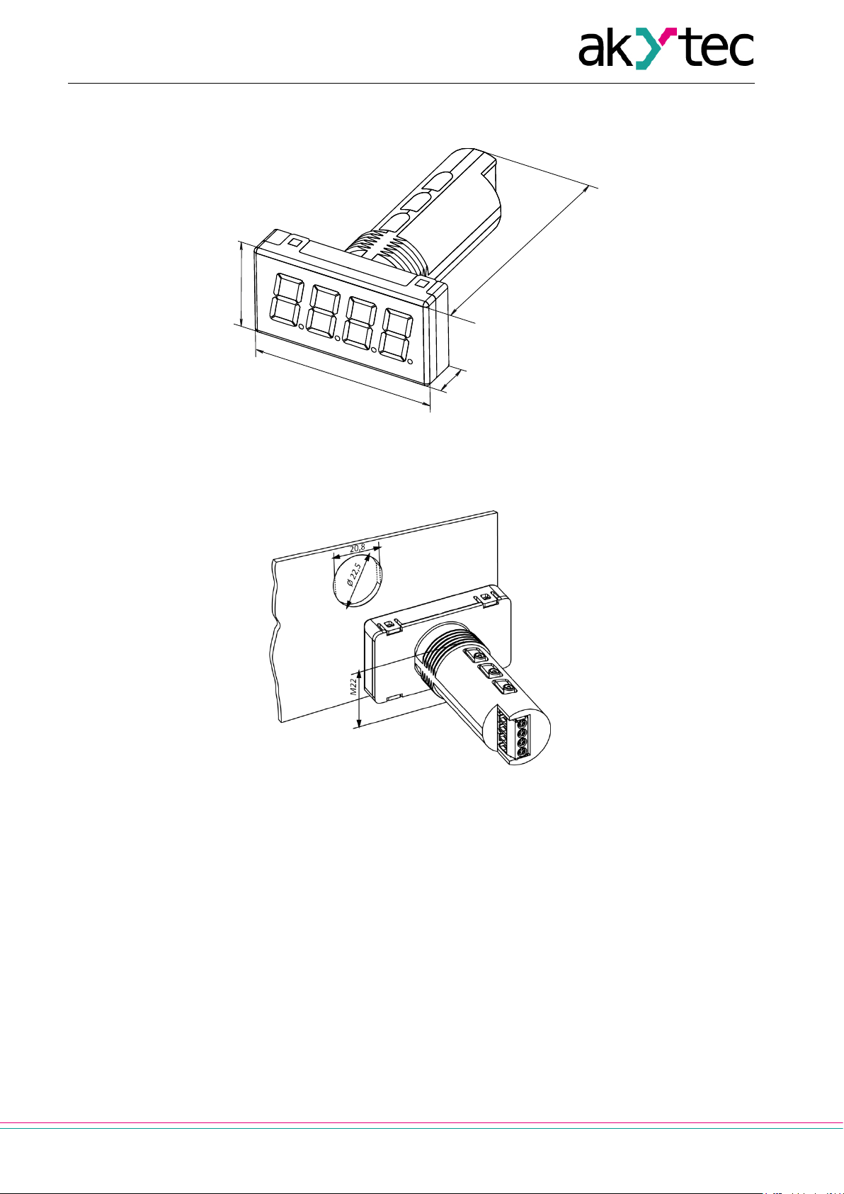
Appendix A Dimensions
Appendix A Dimensions
Fig. A1
To prevent the device spinning, the borehole in the front panel must correspond to the dimensions in Fig. A2.
Fig. A2
akYtec GmbH · Vahrenwalder Str. 269 A · 30179 Hannover · Germany · Tel.: +49 (0) 511 16 59 672-0 · www.akytec.de
Page 15

14
1
2
3
4
24 V DC
+
B/-
А/+
-
RS485
SMI2
Appendix B Electrical connection
Appendix B Electrical connection
Fig. B1
akYtec GmbH · Vahrenwalder Str. 269 A · 30179 Hannover · Germany · Tel.: +49 (0) 511 16 59 672-0 · www.akytec.de
Page 16

15
Appendix C Communication protocol
Appendix C Communication protocol
The device supports the following protocols: Modbus RTU, Modbus ASCII and akYtec. The protocol akYtec
is an internal protocol and is used by the configuration software.
C.1 Addressing
The device receives an individual address so that it can be addressed selectively.
The broadcast address is a reserved address that can be used to address all devices.
The individual addresses are from 1 to 247; the address 0 is reserved as a broadcast address.
If the device has the address 0, it is addressed with every address, but does not send a response.
The device address is set in the parameter Addr. The factory setting is 16.
C.2 Master
Every participant may send messages. However, these are normally initiated by the master and answered by
an addressed slave.
A PLC or a PC with an RS232/485 converter and/or USB/RS485 converter can serve as a master in the
RS485 network.
There may only be one master in a RS485 network.
akYtec GmbH · Vahrenwalder Str. 269 A · 30179 Hannover · Germany · Tel.: +49 (0) 511 16 59 672-0 · www.akytec.de
Page 17

16
Address
Function code
Checksum
12
17
ZZ
Address
Function code
Data length (byte)
Data
Checksum
12
17
14
SMI2 VX.YY
ZZ
Appendix D Functions and data transfer
Appendix D Functions and data transfer
The following functions are supported in the Modbus protocol:
– 03, 04 (read registers) – read one or more registers;
– 06 (write single register) – write one register;
– 16 (write multiple registers) – write block of registers;
– 17 (report server ID) – read the device name and the firmware version.
Example. Function 17 (Report Server ID)
This function is used to read the device name and the firmware version. The example with the device address 12 is shown in Tables D1 and D2
Table D1 Format of the request (Master -> Slave)
Table D2 Format of the response (Slave -> Master)
Comments
The values X and YY are set by the manufacturer.
akYtec GmbH · Vahrenwalder Str. 269 A · 30179 Hannover · Germany · Tel.: +49 (0) 511 16 59 672-0 · www.akytec.de
Page 18
17
Register
no. (dec)
Device information
Device name
0-1
SMI2
Char[8]
read only
Firmware version
2-3
X.YY
Char[4]
read only
Network parameters
Baud rate
4
0 – 2.4 kBd
byte
read/write
Data bits
Len
5
7 8 byte
read/write
Parity
6
0 - none
byte
read/write
Stop bits
Sbit
7
1 – one
byte
read/write
Response delay
rS.dL
8
0…45…255 ms
byte
read/write
Time-out
t.out
9
0…600 s
UInt16
read/write
Device address
Addr
10
Modbus: 1…16…247
UInt16
read/write
Protocol
11
0 – Modbus ASCII
2 – akYtec
byte
read/write
Address bits
A.Len
12
8 – 8 bit
byte
read/write
Last error code
13
0…255
always 0
byte
read only
see Table D5
Broadband offset
Ad.Ad
16
0…1000…65535
UInt16
(2 bytes)
read/write
Master/Slave mode
dEv.r
40
0 – Slave
byte
read/write
Slave address *)
SLA.A
41
1…16…247
UInt16
read/write
Start address *)
SLA.r
42
0…65535
UInt16
read/write
Query cycle*)
SLA.P
43
0…10…255
byte
read/write
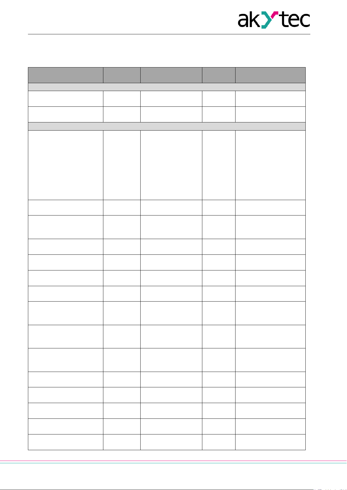
Appendix D Functions and data transfer
D.1 Parameters
Comment: Default values are printed in bold.
Table D3 Configuration parameters
dEv
vEr
bPS
PrtY
Parameter
Values Data type Comment
1 – 4.8 kBd
2 – 9.6 kBd
3 – 14.4 kBd
4 – 19.2 kBd
5 – 28.8 kBd
6 – 38.4 kBd
7 – 57.6 kBd
8 – 115.2 kBd
1 - even
2 - odd
(8 bytes)
(8 bytes)
not displayed
t.Pro
(only akYtec protocol)
n.Err
2 – two
(2 bytes)
akYtec: 0…16…2047
(2 bytes)
1 – Modbus RTU
11 – 11 bit
At switch on -
not displayed
1 – Master
(2 bytes)
(2 bytes)
akYtec GmbH · Vahrenwalder Str. 269 A · 30179 Hannover · Germany · Tel.: +49 (0) 511 16 59 672-0 · www.akytec.de
x100 ms
Page 19

18
Modbus function *)
SLA.F
44
3 – 0x0003
4 – 0x0004
byte
read/write
Operating parameters
Data type
17
0 – Int
byte
read/write
Decimal point position
18
0 (- - - -)
4 (-.- - -)
byte
read/write
Flash interval
PF
19
200 … 9999 ms
UInt16
(2 bytes)
read/write
Alarm logic
20
0 – off
2 – U-Logic
byte
read/write
Setpoint
C.SP
21-22
-999 … 0.0 … +9999
Single
(8 bytes)
read/write
Hysteresis (Δ)
HYST
23-24
0 … 10.0 … 9999
Single
(8 bytes)
read/write
Register
Status byte
14
0 … 255
byte
Read only
Data type Int value
val.I
25
-32768 … 0 … 32767
Int16
read/write
Data type Word value
val.W
26
0 … 65535
UInt16
read/write
Data type Float value
27-28
0.0
Single
read/write
Data type String value
29-32
see **)
Char [8]
read/write
Data type Image value
33-34
see **)
Char [4]
read/write
Display mode for data type
35
0 – flashing off
byte
read/write
Actual state of the display
O.Str
36-37
see ***)
Char [4]
read only
Standard display mode
O.mod
38
0×00 – flashing off
byte
read only
Command
15
0x81
byte
Save changed parame-
Appendix D Functions and data transfer
dAtA
1 – Word
2 – Float
3 – String[8]
4 – Image
dP
1 (- - - -.)
2 (- - -.-)
3 (- -.- -)
AL.t
1 – ∩-Logic
Table D4 Transmitted data
Comment: not displayed during the Configuration check (see 5.4).
Parameter
Stat
val.F
val.S
val.P
String and Image
ind.M
segments
no. (dec)
Values Data type Comment
default – (- - - -)
default – ( )
1 – flashing on
0×ВB – flashing on
(2 bytes)
(2 bytes)
(8 bytes)
(8 bytes)
(4 bytes)
(4 bytes)
Bit 0 – EEPROM error
Bit 1 – Parameter error
Aply
akYtec GmbH · Vahrenwalder Str. 269 A · 30179 Hannover · Germany · Tel.: +49 (0) 511 16 59 672-0 · www.akytec.de
default – 0
ters
Page 20
19
0
Error-free frame transmission
1
Illegal function
2
Set decimal point position larger than 4
3
Write access to read-only memory
33
Framing error
39
Incorrect checksum
40
Descriptor not found
49
Actual memory area smaller than indicated
Segment
Bit
A 7 B
6
D 4 E 3 F 2 G 1 DP
0
Appendix D Functions and data transfer
Comments
*) Available only in master mode
**) The display supports the following characters:
Figures 0 … 9;
Upper and lower case letters of the Latin alphabet;
Symbols " ", "_", "–", "."
Examples: 1) char[8] = "A.B.C.D"; 2) char[8] = "ABCD"; 3) char[8] = "ABCD."
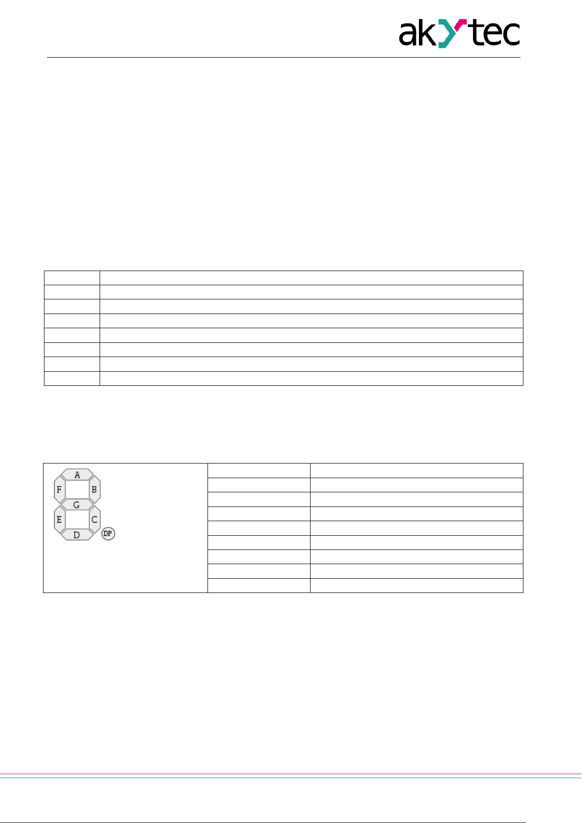
***) 4 bytes data shows the status of each display segment. The first byte is reserved for the first digit
from the right. The allocation of bits for the individual segments is described in Table D6.
D.2 Error codes
Table D5
D.3 Segment addressing
Table D6
C 5
akYtec GmbH · Vahrenwalder Str. 269 A · 30179 Hannover · Germany · Tel.: +49 (0) 511 16 59 672-0 · www.akytec.de
Page 21
20
ASCII-
– .
– .
0 1 2 3 4 5 6 7 8 9
0 1 2 3 4 5 6 7 8
9
A B C D E F G H I J K L M N
O
A b C d E F G H i J K L M N
O
P Q R S T U V W X Y Z
_
P Q R S t U V W X Y Z
_
a b c d e f g h i j k l m n
o
a b c d E F G h i J K L M n
o
p q r s t u v w x y z
P Q r S t U V W X Y Z
Device address:
0x64 (100)
Function code:
0x10 (16)
Starting address:
0x1D (29)
Number of registers:
0x02 (2)
Data length (byte):
0x04 (4)
Data:
0x57(W) 0x4F(O) 0x52(R) 0x44(D)
CRC:
0xC0 0x07
Device address:
0x64 (100)
Function code:
0x10 (16)
Starting address:
0x1D (29)
Number of registers:
0x04 (4)
Data length (byte):
0x08 (8)
Data:
0x57(W) 0x2E(.) 0x4F(O) 0x2E(.) 0x52(R) 0x2E(.) 0x44(D) 0x2E(.)
CRC:
0x90 0x31
Appendix D Functions and data transfer
D.4 Symbol presentation
Table D7 ASCII code and the symbol presentation
Code
.0 .1 .2 .3 .4 .5 .6 .7 .8 .9 .A .B .C .D .E .F
2.
3.
4.
5.
6.
7.
D.5 Examples
Example 1
The device with the address 100 should display the text WORD.
Request:
64 10 00 1D 00 02 04 57 4F 52 44 C0 07
Example 2
The device with the address 100 should display the text W.O.R.D..
Request:
64 10 00 1D 00 04 08 57 2E 4F 2E 52 2E 44 2E 90 31
akYtec GmbH · Vahrenwalder Str. 269 A · 30179 Hannover · Germany · Tel.: +49 (0) 511 16 59 672-0 · www.akytec.de
 Loading...