

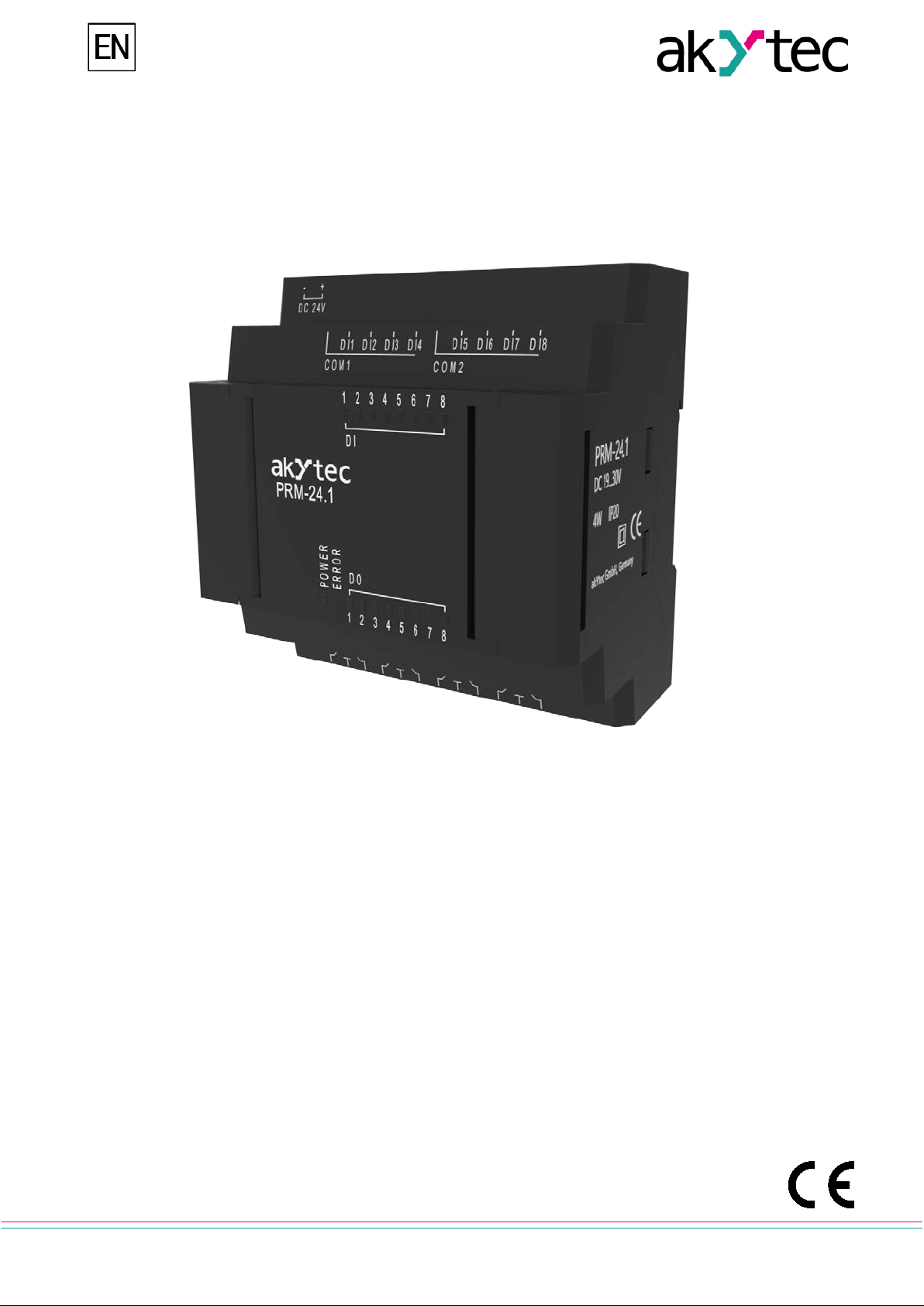
PRM
Extension module
User guide
PRM_2018.03_0276_EN
© All rights reserved
Subject to technical changes and misprints
akYtec GmbH · Vahrenwalder Str. 269 A · 30179 Hannover · Germany · Tel.: +49 (0) 511 16 59 672-0 · www.akytec.de

1
Contents
1. Overview .......................................................................................................................................................... 2
2. Specifications ................................................................................................................................................. 3
2.1 Environmental conditions .......................................................................................................................... 4
2.2 Galvanic isolation ...................................................................................................................................... 4
3. Safety ............................................................................................................................................................... 5
3.1 Intended use .............................................................................................................................................. 5
4. Mounting ......................................................................................................................................................... 6
4.1 Intended use .............................................................................................................................................. 6
4.2 Internal bus ................................................................................................................................................ 6
4.3 Wiring ........................................................................................................................................................ 7
4.4 Quick replacement .................................................................................................................................... 8
5. Configuration .................................................................................................................................................. 9
5.1 Firmware update ..................................................................................................................................... 10
6. Maintenance .................................................................................................................................................. 11
7. Transportation and storage ......................................................................................................................... 12
8. Scope of delivery .......................................................................................................................................... 13
Appendix A Dimensions ................................................................................................................................... 14
akYtec GmbH · Vahrenwalder Str. 269 A · 30179 Hannover · Germany · Tel.: +49 (0) 511 16 59 672-0 · www.akytec.de
2
►
Each PRM module is powered independently of the basic device. The basic device and the
modules may have different supply voltages.
PRM-230.1
POWER
ERROR
1 21 2
- +
3 4 5 6 7 8 9 10 11 12
13 14 15 16 17 18 19 20 21 22 23 24
DC 24V AC 230V
L N
COM 1 COM 2
DI1 DI2 DI3 DI4 DI5 DI6 DI7 DI8
DI
1 2 3 4 5 6 7 8
1 2 3 4 5 6 7 8
DO
DO1 DO2 DO3 DO4 DO5 DO6 DO7 DO8
Digital inputsPower supply
Digital outputs
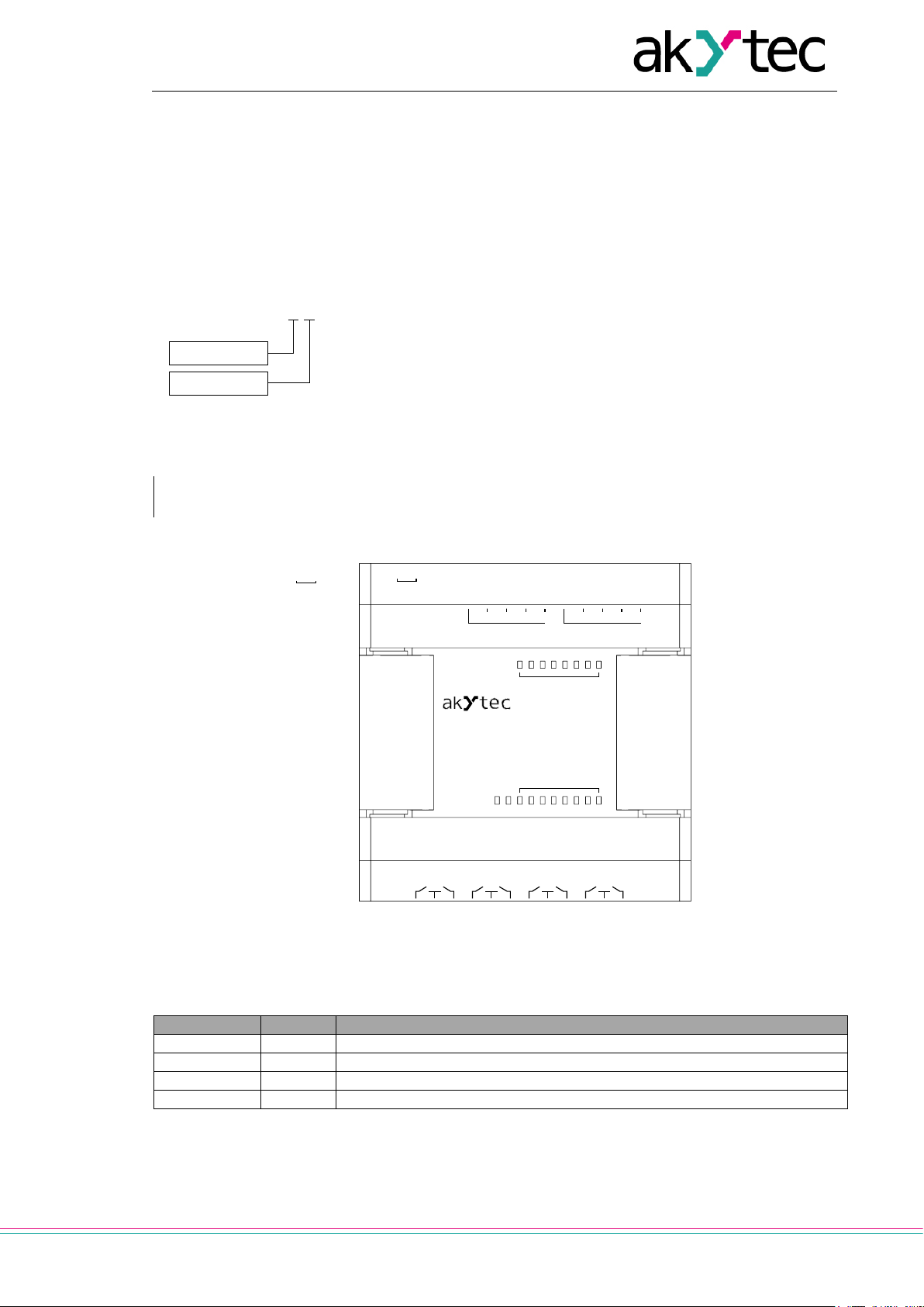
Indicator
Color
Description
POWER
green
Lights if the power supply is on
ERROR
red
Flashes if the communication with the basic device is interrupted
DI1…DI8
yellow
Indicates the state of the input (lights = on)
DO1…DO8
yellow
Indicates the state of the output (lights = on)
PRM-X.1
Supply voltage
I/O
Overview
1. Overview
PRM extension module provides additional inputs and outputs for the basic device PR200. The
module inputs and outputs can be controlled by PR200 as its own I/Os.
The module is a passive device and cannot be used without connection with the basic device over
internal bus.
The module is manufactured in several modifications, differing by the supply voltage. All modifications are designed in a plastic enclosure for DIN rail mounting.
Ordering code:
NOTICE
Supply voltage
230 - 230 (94…264) V AC
24 - 24 (19…30) V DC
I/O
1 - 8 DI, 8 DO
Ordering example:
PRM-230.1 – extension module with 230 VAC supply voltage, 8 230 VAC digital inputs and 8 relay
outputs.
Table 1.1 LED indicators
Fig. 1.1
akYtec GmbH · Vahrenwalder Str. 269 A · 30179 Hannover · Germany · Tel.: +49 (0) 511 16 59 672-0 · www.akytec.de
3
Device
PRM-230.1
PRM-24.1
230 (94…264) V AC;
50 (47…63) Hz
Power consumption, max
8 VA
4 W
Galvanic isolation
2830 V
1780 V
Appliance class
II
Digital inputs 8 8
Digital outputs 8 8
Internal bus
Frequency
2.25 MHz
Packet rate (each 16 bit)
4000 packet/s
Max. module number
2
LEDs
18
Dimensions (with terminal blocks)
88 x 108 x 58 mm
Mounting
DIN rail (35 mm)
Weight
approx. 250 g
IP class
IP20
Device
PRM-230.1
PRM-24.1
Switch contact
Input voltage
230 V AC
24 V DC
Input voltage, max
264 V AC
30 V DC
159…264 V (0.75…1.5
Logical 0
0…40 V (0…0.5 mA)
-3…+5 V (0…1 mA)
Pulse length, min
50 ms
2 ms
Response time, max
100 ms
30 ms
Galvanic isolation
in groups of 4 (1-4, 5-8)
Test voltage between groups
1780 V
Test voltage against other circuits
2830 V
Device
PRM-230.1
PRM-24.1
Type
Relay (NO)
Switching capacity AC
5 A, 250 V (resistive load)
Switching capacity DC
3 A, 30 V
Minimum load current
10 mA (at 5 V DC)
Service life, electrical
5 A, 250 V AC (resistive load)
100,000 switching cycles
3 A, 30 V DC
200,000 switching cycles
Galvanic isolation
in groups of 2 (1-2, 3-4, 5-6, 7-8)
Test voltage between groups
1780 V
Test voltage against other circuits
2830 V
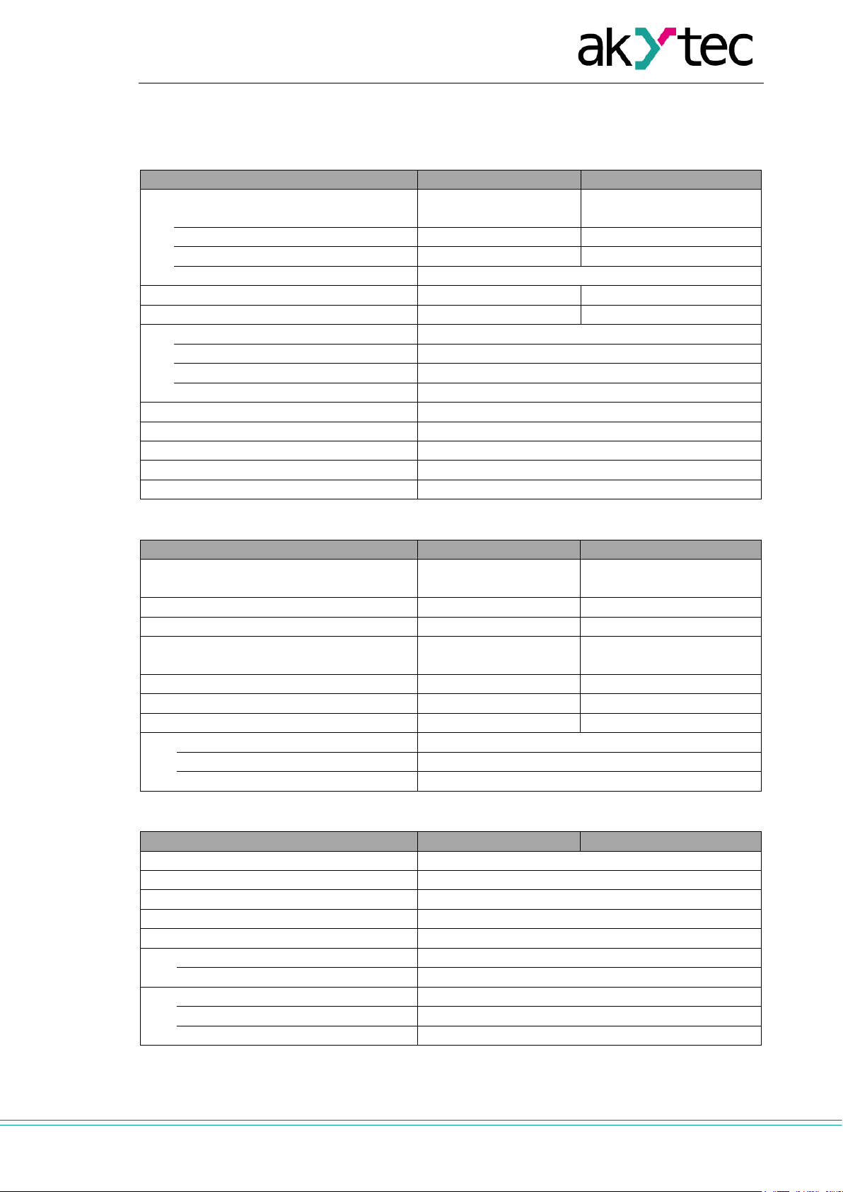
Specifications
2. Specifications
Table 2.1 General specification
Power supply
Table 2.2 Digital inputs
Input signal Switch contact
24 (19…30) V DC
PNP with open collector
Logical 1
Table 2.3 Digital outputs
mA)
15…30 V (5 mA)
akYtec GmbH · Vahrenwalder Str. 269 A · 30179 Hannover · Germany · Tel.: +49 (0) 511 16 59 672-0 · www.akytec.de
4
Conditions
Permissible range
Ambient operating temperature
-20…+55°C
Storage temperature
-25…+55°C
Relative humidity
up to 80% (at +25°C, non-condensing)
Altitude
up to 2000 m above sea level
EMC immunity
conforms to IEC 61000-6-2
EMC emission
conforms to IEC 61000-6-4
a)
230V AC
DI1...DI4 DI5...DI8
2830 V 2830 V 2830 V
1780V
1780V
2830 V 2830 V
DO1 DO2 DO7 DO8
Internal bus Internal bus
b)
24V DC
DI1...DI4 DI5...DI8
2830 V 2830 V 2830 V
1780V
1780V
2830 V 2830 V
DO1 DO2 DO7 DO8
Internal bus Internal bus
Specifications
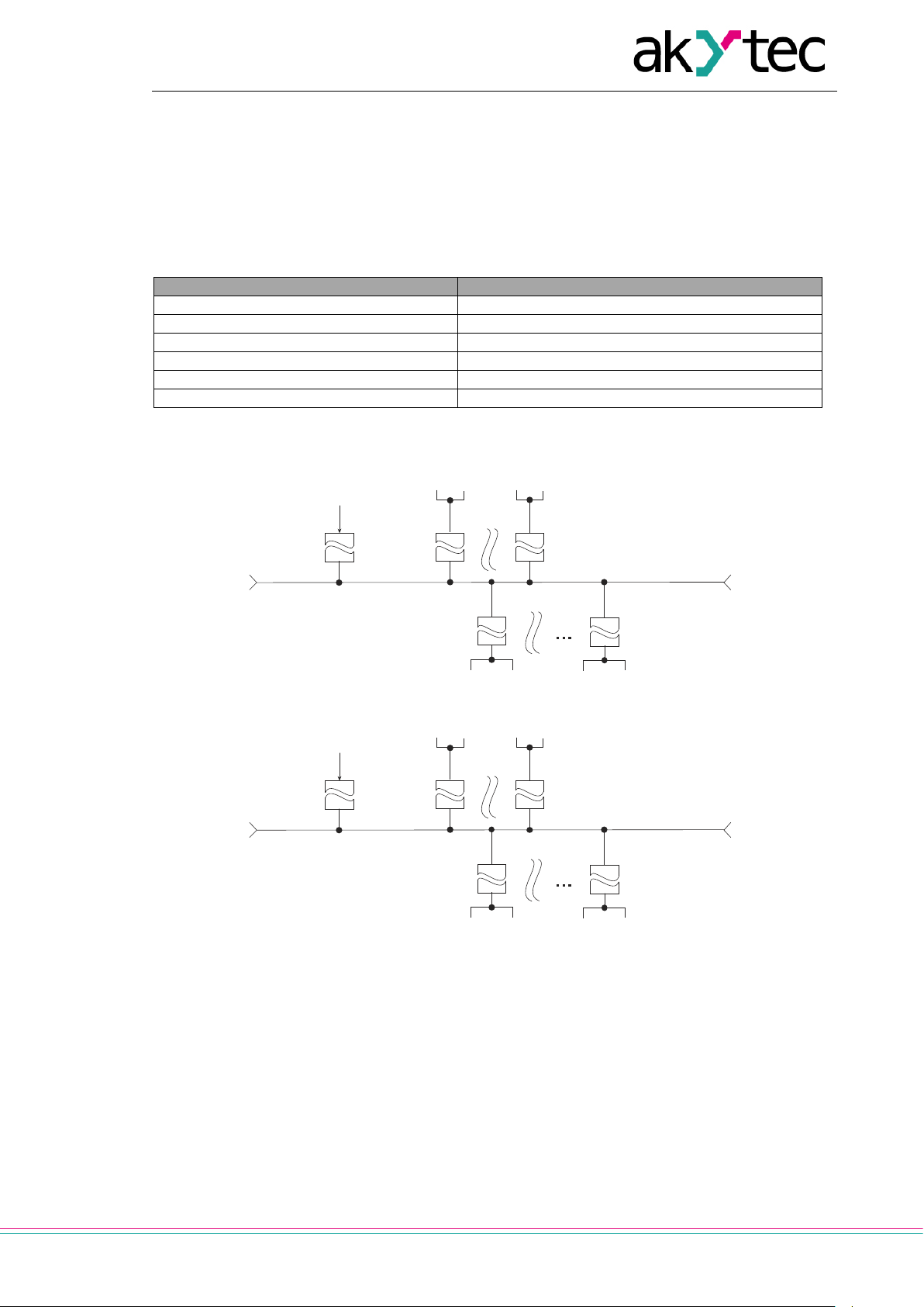
2.1 Environmental conditions
The device is designed for natural convection cooling. It should be taken into account when choosing the installation site.
The following environment conditions must be observed:
− clean, dry and controlled environment, low dust level
− closed non-hazardous areas, free of corrosive or flammable gases
Table 2.4
2.2 Galvanic isolation
akYtec GmbH · Vahrenwalder Str. 269 A · 30179 Hannover · Germany · Tel.: +49 (0) 511 16 59 672-0 · www.akytec.de
Fig. 2.1 Galvanic isolation PRM-230 (a) and PRM-24 (b)

5
DANGER
DANGER indicates an imminently hazardous situation which, if not avoided, will result in
death or serious injury.
WARNING indicates a potentially hazardous situation which, if not avoide d, could result in
CAUTION indicates a potentially hazardous situation which, if not avoided, could result in
minor or moderate injury.
►
NOTICE indicates a potentially harmful situation which, if not avoided, may result in damage of the product itself or of adjacent objects.
Safety
3. Safety
Explanation of the symbols and keywords used:
WARNING
CAUTION
NOTICE
death or serious injury.
3.1 Intended use
Extension modules of PRM series have been designed and built solely for the intended use described in this manual, and may only be used accordingly. The technical specifications contained in
this manual must be observed.
The module may be operated only in properly installed condition.
Improper use
Any other use is considered improper. Especially to note:
– This device should not be used for medical devices which receive, control or otherwise affect
human life or physical health.
– The device should not be used in an explosive environment.
– The device should not be used in an atmosphere with chemically active substance.
akYtec GmbH · Vahrenwalder Str. 269 A · 30179 Hannover · Germany · Tel.: +49 (0) 511 16 59 672-0 · www.akytec.de

6
DANGER
WARNING
Improper installation can cause seriou s or minor injuries or device damage.
Ensure that the mains voltage matches the voltage marked on the nameplate!
Do not feed any external devices from the p ower contacts of the device.
►
It is necessary to observe the polarity while connecting 24V power sources. Improper
connection can damage the device.
►
Supply voltage for 24 VDC models may not exceed 30 V. Higher voltage can damage the
device.
►
►
►
Removing of the terminal blocks may be performed only after powering off the device and
all connected equipment.
►
Before switching on, make sure that the device was stored at the specified ambient temperature (-20 ... +55 °C) for at least 30 minutes.
Mounting
4. Mounting
The extension module PRM is designed for DIN rail mounting. For the dimension drawing see Appendix A.
The safety precautions from the section 4.1 and the operating conditions from the section 2.1 must
be observed.
After mounting on the DIN rail, first the internal bus connection should be implemented (see 4.2 ‘Internal bus’), then the power supply and the external devices should be connected to the module
terminal blocks (see 4.3 ‘Wiring’).
For device quick replacement see 4.4.
4.1 Intended use
The device must be powered off before connecting to internal bus or I/O devices.
Installation must be performed only by fully qualified personnel.
WARNING
NOTICE
Ensure that the device is provided with i ts own power supply line and electric fuse!
NOTICE
If the supply voltage is lower than 19 V DC, the device cannot operate properly but will not be damaged.
NOTICE Signal cables should be routed separately or screened from the supply cables.
NOTICE
Shielded cable should be used for the signal lines to ensure the EMC precautions.
NOTICE
NOTICE
4.2 Internal bus
A high-speed internal bus that connects PR200 to PRM modules provides the same high-speed
performance of the module I/Os that of the built-in I/Os of the basic device. This allows reading the
module input vales and writing the module output values within one cycle of the program running
on PR200.
The PRM modules are con nec ted to PR2 00 in seri es . Maximum two modules can be connected
(Fig. 4.1). To implement the internal bus, connect PRM to PR200, using the 4.5 cm flat cable included to the module.
PRM has two connectors marked ‘EXT’ located under the right and left covers on the device front.
The connector under the left cover is used to connect the 1st PRM to PR200 or the 2nd PRM to the
akYtec GmbH · Vahrenwalder Str. 269 A · 30179 Hannover · Germany · Tel.: +49 (0) 511 16 59 672-0 · www.akytec.de

7
AC230V L /
DC24V -
AC230V N /
DC24V +
3
COM1
Common minus pole DI1...DI4
15
DO2
Digital output DO2
4
DI1
Digital input DI1
16
DO3
Digital output DO3
5
DI2
Digital input DI2
17 - Common contact DO3...DO4
6
DI3
Digital input DI3
18
DO4
Digital output DO4
7
DI4
Digital input DI4
19
DO5
Digital output DO5
8
COM2
Common minus pole DI5...DI8
20 - Common contact DO5...DO6
9
DI5
Digital input DI5
21
DO6
Digital output DO6
10
DI6
Digital input DI6
22
DO7
Digital output DO7
11
DI7
Digital input DI7
23 - Common contact DO7...DO8
12
DI8
Digital input DI8
24
DO8
Digital output DO8
Mounting
1st one. The connector under the right cover is used to connect PR200 to the 1st PRM or the 1st
PRM to the 2nd one.
To enable control by PR200, the module should be added to the PR200 configuration in the programming software ALP (see 5 ‘Configuration’).
Fig. 4.1
When connected, the flat cable should be placed in a special recess under the cover to enable
PRM to be pushed close to PR200.
Fig. 4.2
4.3 Wiring
The safety precautions from the section 4.1 must be observed.
Terminal assignment is given in Table 4.1. Electrical connections for inputs and outputs are given
in Fig. 4.3…4.5. Maximum conductor cross-section is 0.75 mm².
Table 4.1 Terminal assignment
№ Designation Function № Designation Function
1
2
Power supply AC / DC * 13 DO1 Digital output DO1
Power supp ly AC / DC * 14 - Common contact DO1...DO2
* Depending on the device modification (PRM-230 or PRM-24)
akYtec GmbH · Vahrenwalder Str. 269 A · 30179 Hannover · Germany · Tel.: +49 (0) 511 16 59 672-0 · www.akytec.de

8
►
PRM-230 (230 V AC)
ated on the same phase. Different phases are not allowed.
13 14 15 16 17 18 19 20 21 22 23 24
Mounting
Fig. 4.3 Connection of switch contacts to digital inputs: a) PRM-24, b) PRM-23
a b
NOTICE
The digital inputs are divided into two groups , each of four inputs. All inputs must be oper-
Fig. 4.4 Connection of 3-wire sensors to PNP transistor inputs (PRM-230 only)
For PRM-24, it is allowed to connect sensors with switch contacts and transistor outputs within the
same input group. One voltage source can be used for two input groups.
Fig. 4.5 Relay outputs
4.4 Quick replacement
PRM is equipped with plug-in terminal blocks which
enable quick replacement of the device without disconnecting the existing wiring (Fig. 4.6).
To replace the device:
− power off all connected lines including power supply
− remove all detachable parts of the terminal blocks
− replace PRM
− connect detach abl e par ts with exis tin g wirin g to the
device
akYtec GmbH · Vahrenwalder Str. 269 A · 30179 Hannover · Germany · Tel.: +49 (0) 511 16 59 672-0 · www.akytec.de
Fig. 4.6 Quick replacement

9
Configuration
5. Configuration
To add a module to the basic device configuration:
– open a PR200 project in ALP programming software
– open the tool ‘Device configuration’
– select the item ‘Extension modules’
– add PRM module using the context menu (Fig. 5.1)
Fig. 5.1
The PRM counting number, when counting from left to right from PR200, determines the slot number in the configuration (Fig. 4.1). The module next to PR200 should be added to the configuration
first to be assigned to the slot 1. The next added module is always assigned to the slot 2. If there is
no module assigned to the slot 1, it is impossible to assign the module to the slot 2.
The data exchange between PR200 and PRM at the slot 2 is carried out through PRM at the slot 1.
If PRM at the slot 1 is powered off, the data exchange between PR200 and PRM at the slot 2 is interrupted.
You can remove PRM from the project only after disconnecting all the variables connected to its
inputs and outputs.
You can change the position of PRM in the configuration using the context menu.
The project can be transferred to P200 irrespective of whether the modules are connected or not.
When a module is added to configuration, additional inputs I1…I8
and outputs O1…O8 with the module number in brackets appear in
the workspace (Fig. 5.2).
The inputs from I6 (1) to I8 (1) are the inputs 6…8 of the module at
the slot 1.
The inputs from I1 (2) to I2 (2) are the inputs 1, 2 of the module at
the slot 2
When have been added to the project, the module is ready for operation. The following optional settings can be made:
Fig. 5.2
1. Status – a parameter to witch a Boolean variable in the project can be assigned. The value of
the parameter is:
akYtec GmbH · Vahrenwalder Str. 269 A · 30179 Hannover · Germany · Tel.: +49 (0) 511 16 59 672-0 · www.akytec.de

10
►
NOTICE
It is not recommended to use the contact bounce suppression for input signals with a frequency above 90 Hz and a duty cycle of 50% or less. A useful signal can be missed.
Configuration
– TRUE, if the communication with PRM is established and the modification of PRM matches
the one specified in the project
– FALSE, if the communication with the module is lost or the modification of PRM does not
match the one specified in the project
2. Output safe state – the parameter can be set for each output using the item ‘Outputs \ Digi-
tal’ in the configuration tree. The parameter defines the safe output state if communication with
PR200 has been interrupted.
3. Debouncing filter – the parameter is available only for inputs of PRM-24. It can be set for
each input using the item ‘Inputs \ Digital’ in the configuration tree. The parameter defines the
input filter time for contact bounce suppression and can be set in the range of 0…255 ms.
5.1 Firmware update
When communication between akYtec ALP software and PR200 with PRM(s) connected is established, you can check all devices for firmware update. If a firmware update is available, it will be
prompted to install it on the basic device and the modules.
akYtec GmbH · Vahrenwalder Str. 269 A · 30179 Hannover · Germany · Tel.: +49 (0) 511 16 59 672-0 · www.akytec.de

11
Maintenance
6. Maintenance
The maintenance includes:
− cleaning of the housing and terminal blocks from dust, dirt and debris
− check the device fastening
− checking the wiring (connecting leads, fastenings, mechanical damage)
The device should be cleaned with a damp cloth only. No abrasives or solvent-containing cleaners
may be used. The safety information in section 3 must be observed when carrying out maintenance.
akYtec GmbH · Vahrenwalder Str. 269 A · 30179 Hannover · Germany · Tel.: +49 (0) 511 16 59 672-0 · www.akytec.de

12
►
The device may have been damaged during transportati o n.
Report the transport damage immediately to the shipper and akYtec GmbH!
Transportation and storage
7. Transportation and storage
Pack the device in such a way as to protect it reliably against impact for storage and transportation.
The original packaging provides optimum protection.
If the device is not taken immediately after delivery into operation, it must be carefully stored at a
protected location. The device should not be stored in an atmosphere with chemically active substances.
Permitted storage temperature: -25...+ 55 °C
NOTICE
Check the device for transport damage and completeness!
akYtec GmbH · Vahrenwalder Str. 269 A · 30179 Hannover · Germany · Tel.: +49 (0) 511 16 59 672-0 · www.akytec.de

13
Scope of delivery
8. Scope of delivery
– PRM 1
– Short guide 1
– Connecting cable 1
– Terminal blocks (set) 1
akYtec GmbH · Vahrenwalder Str. 269 A · 30179 Hannover · Germany · Tel.: +49 (0) 511 16 59 672-0 · www.akytec.de

14
88
58
90
Appendix A Dimensions
Appendix A Dimensions
Fig A.1
akYtec GmbH · Vahrenwalder Str. 269 A · 30179 Hannover · Germany · Tel.: +49 (0) 511 16 59 672-0 · www.akytec.de
 Loading...