

Page 1
akYtec GmbH · Vahrenwalder Str. 269 A · 30179 Hannover · Germany · Tel.: +49 (0) 511 16 59 672-0 · www.akytec.de
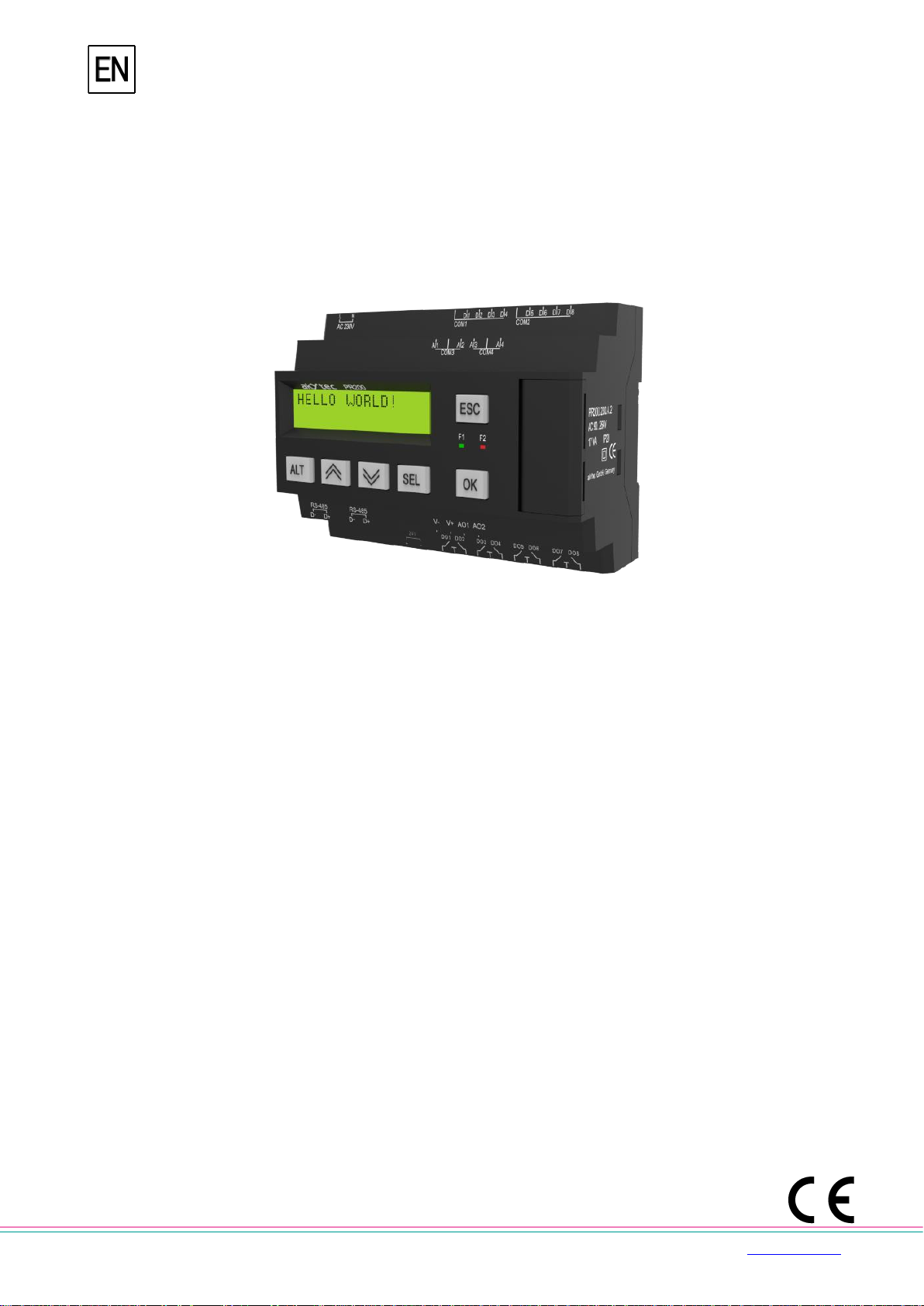
PR200
Programmable relay
User guide
PR200_2021.01_0309_EN
© All rights reserved
Subject to technical changes and misprints
Page 2

akYtec GmbH · Vahrenwalder Str. 269 A · 30179 Hannover · Germany · Tel.: +49 (0) 511 16 59 672-0 · www.akytec.de
1
Contents
Contents ................................................................................................................................................................. 1
Introduction ............................................................................................................................................................ 2
1 Overview ........................................................................................................................................................ 3
1.1 Intended use .............................................................................................................................................. 4
1.2 Ordering key .............................................................................................................................................. 4
2 Specifications ................................................................................................................................................ 5
2.1 Environmental conditions ....................................................................................................................... 7
3 Installation ..................................................................................................................................................... 8
3.1 Mounting .................................................................................................................................................... 8
3.2 Wiring ......................................................................................................................................................... 8
3.2.1 Inputs ................................................................................................................................................ 9
3.2.2 Outputs ........................................................................................................................................... 10
3.2.3 Terminal assignment ..................................................................................................................... 10
3.3 Quick replacement.................................................................................................................................. 11
4 Hardware resources ................................................................................................................................... 12
4.1 Analog inputs AI1…AI4 .......................................................................................................................... 12
4.1.1 Analog mode .................................................................................................................................. 13
4.1.2 Digital mode.................................................................................................................................... 14
4.1.3 Analog input filtering ..................................................................................................................... 14
4.2 Analog outputs AO1, AO2 ..................................................................................................................... 14
4.3 RS485 interface ....................................................................................................................................... 15
4.3.1 Slave mode ..................................................................................................................................... 15
4.3.2 Master mode ................................................................................................................................... 17
4.4 Service modes ........................................................................................................................................ 19
5 Operation ..................................................................................................................................................... 21
5.1 Error mode .............................................................................................................................................. 21
5.2 System menu .......................................................................................................................................... 21
5.2.1 Display navigation ......................................................................................................................... 22
5.2.2 Menu structure ............................................................................................................................... 23
5.3 Display programming ............................................................................................................................. 24
6 Maintenance ................................................................................................................................................ 26
7 Transportation and storage ....................................................................................................................... 27
8 Scope of delivery ........................................................................................................................................ 28
Appendix А. Dimensions .................................................................................................................................. 29
Appendix B. Terminal layouts .......................................................................................................................... 30
Appendix C. Galvanic isolation ........................................................................................................................ 33
Appendix D. Circuit diagrams .......................................................................................................................... 35
Appendix E. Calibration .................................................................................................................................... 36
E.1 General .................................................................................................................................................... 36
E.2 Input ......................................................................................................................................................... 36
E.3 Output 4-20 mA ....................................................................................................................................... 37
E.4 Output 0-10 V .......................................................................................................................................... 37
Appendix F. Battery replacement .................................................................................................................... 39
Appendix G. Interface card installation ........................................................................................................... 41
Page 3

Introduction
akYtec GmbH · Vahrenwalder Str. 269 A · 30179 Hannover · Germany Tel.: +49 (0) 511 16 59 672-0 · www.akytec.de
2
Introduction
This manual describes the functions, configuration, operating instructions, programming and
troubleshooting of the multifunctional programmable relay PR200 (hereinafter referred to as
PR200, device, or relay).
Terms and abbreviations
ALP – programming software akYtec ALP for programming PR series relays, based on
Function Block Diagram (FBD) programming language
ADC – analog-digital converter
DAC – digital-analog converter
Display element – program element used to display information on the device display
Modbus – application layer messaging protocol for client/server communication between
devices connected on different types of buses or networks, originally published by
Modicon (now Schneider Electric), currently supported by an independent organization
Modbus-IDA (www.modbus.org).
Project – user application created in ALP software that also includes the device
configuration
RAM – random access memory, volatile part of the device memory
Retain memory – non-volatile device memory for retain variables
Retain variable – type of variable that keeps its value after device restart (power off/on
cycle)
ROM – read-only memory, non-volatile part of the device memory
Symbols and key words
DANGER
DANGER indicates an imminent dangerous situation that will result in death or serious
injuries if not prevented.
WARNING
WARNING indicates a potentially dangerous situation that could result in death or serious
injuries.
CAUTION
CAUTION indicates a potentially dangerous situation that could result in minor injuries.
NOTICE
NOTICE indicates a potentially dangerous situation that could result in damage to
property.
NOTE
NOTE indicates helpful tips and recommendations, as well as information for efficient and
trouble-free operation.
Page 4
Overview
akYtec GmbH · Vahrenwalder Str. 269 A · 30179 Hannover · Germany Tel.: +49 (0) 511 16 59 672-0 · www.akytec.de
3
1 Overview
The programmable relay PR200 is a small controller. User program is created as a function
plan with the ALP programming software, which is available for download for free. The ALP
project includes the program as well as the device configuration. Dynamically allocated
memory enables to create complicated programs with many functional blocks, display
elements and advanced display management.
The PR200 enables the following basic functions:
output control according to input statuses and program logic
configuration using ALP software or function buttons
comprehensive display programming
2 programmable LEDs
master and / or slave in Modbus network
Real-time clock
expandable with I/O modules
The relay is available in several versions, for DC and AC voltage, equipped with only digital
or a combination of digital and analog inputs and outputs. The analog inputs can be
configured as analog or as digital. The relay can be expanded with additional I/O modules.
Optional are up to two RS485 interfaces for connection to Modbus networks available.
The device is designed in a plastic enclosure for DIN rail mounting. The enclosure has 3-
level stepped form for distributor installation. Plug-in terminal blocks enable quick and easy
replacement of the device.
Front view:
two-line 32-character alphanumeric LCD display
two LEDs: F1 (green) and F2 (red), program-controlled
6 function buttons for system menu and display navigation
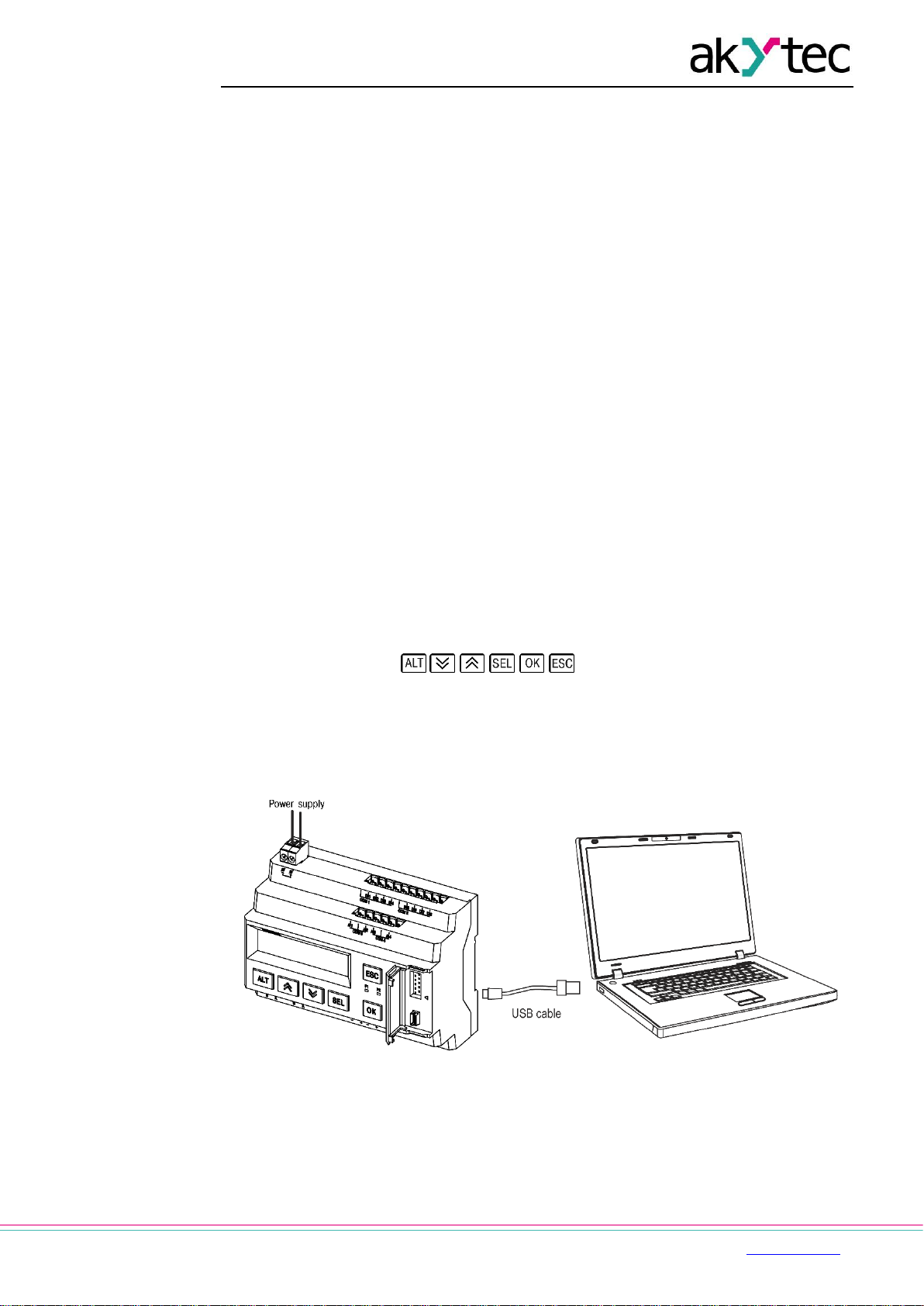
Under the interface cover (to the right):
EXT: 10 pole connector for extension modules
PRG: mini-USB socket for PC connection. USB A-plug to micro B-plug connection
cable is in the package included.
Fig. 1.1 Connection to PC (open interface cover)
Page 5
Overview
akYtec GmbH · Vahrenwalder Str. 269 A · 30179 Hannover · Germany Tel.: +49 (0) 511 16 59 672-0 · www.akytec.de
4
1.1 Intended use
Programmable relays of PR200 series have been designed and built solely for the intended
use described in this manual, and may only be used accordingly. The technical
specifications contained in this manual must be observed. Only by akYtec GmbH
recommended extension modules may be connected to the relay.
The relay may be operated only in properly installed condition.
Improper use
Any other use is considered improper. Especially to note:
– This device should not be used for medical devices which receive, control or
otherwise affect human life or physical health.
– The device should not be used in an explosive environment.
– The device should not be used in an atmosphere with chemically active substance.
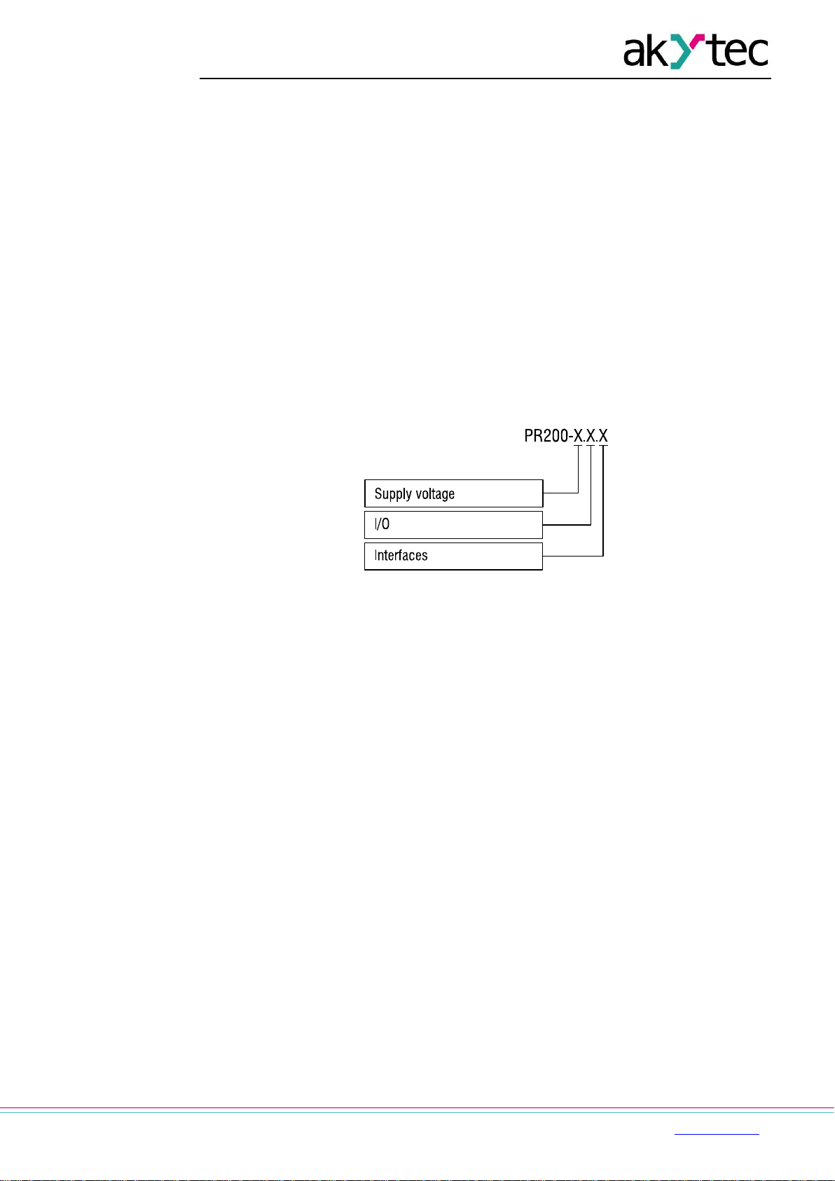
1.2 Ordering key
The relay PR200 can be ordered in various designs depending on the required supply
voltage, number and type of inputs, outputs and interfaces:
Supply voltage
230 - 230 (94…264) V AC
24 - 24 (19…30) V DC
I/O
1 - 8 DI, 6 DO
2 - 8 DI, 4 AI, 8 DO, 2 AO (4-20 mA)
4 - 8 DI, 4 AI, 8 DO, 2 AO (0-10 V)
RS485 interfaces
0 - none *
1 - 1 *
2 - 2
* The models .0 and .1 can be upgraded later by installing up to two interface cards (app. G).
Ordering code for the interface card: PR-IC485
Page 6
Specifications
akYtec GmbH · Vahrenwalder Str. 269 A · 30179 Hannover · Germany Tel.: +49 (0) 511 16 59 672-0 · www.akytec.de
5
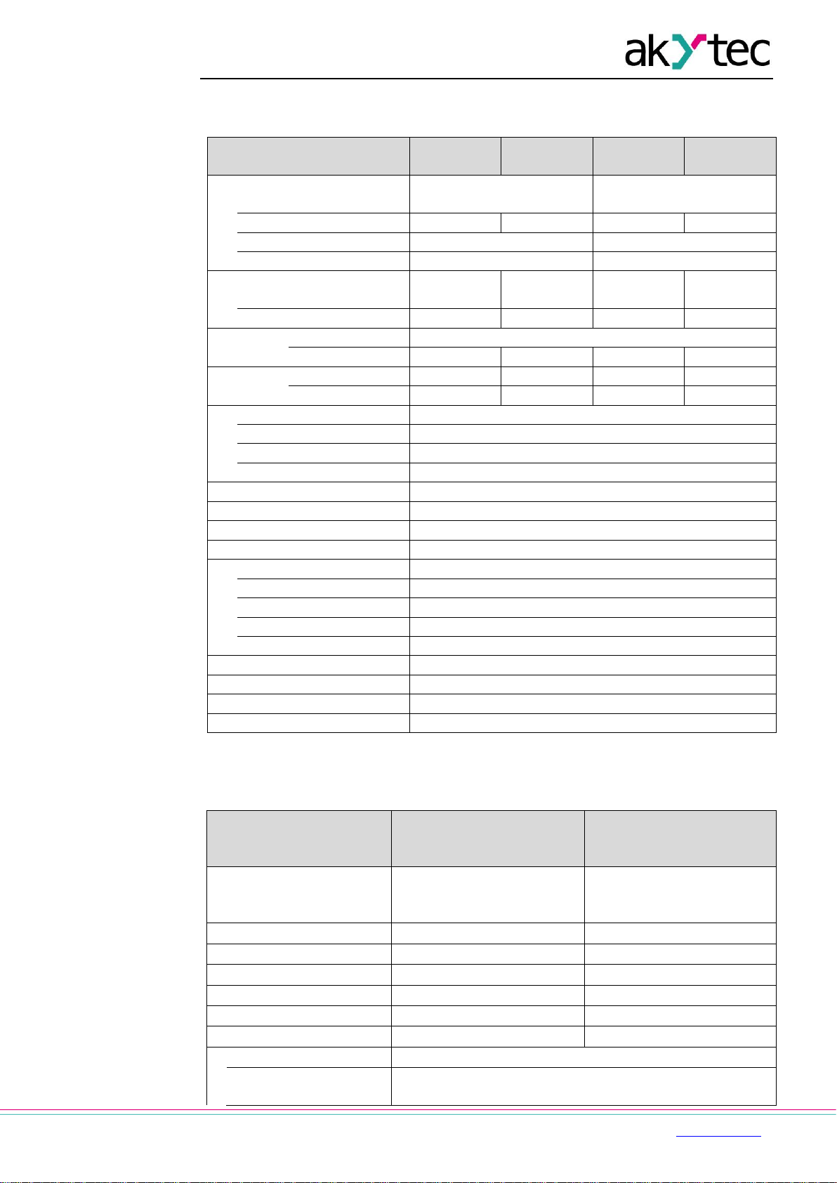
2 Specifications
Table 2.1 General specification
Device
230.1.x
230.2.x
230.4.x
24.1.x
24.2.x
24.4.x
Power supply
230 (94…264) V AC;
50 (47…63) Hz
24 (19…30) V DC
Power consumption, max
10 VA
17 VA
10 W
10 W
Galvanic isolation
2830 V
1780 V
Appliance class
II
III
Integrated voltage source
-
24±3 V DC
100 mA
-
-
Galvanic isolation
-
1780 V - -
Inputs
Digital
8
Analog * - 4 - 4
Outputs
Digital (relay)
6 8 6
8
Analog - 2 - 2
Programming
Software
akYtec ALP
Interface
Mini USB 2.0
Program cycle, min
1 ms
Function buttons
6
LEDs
F1 (green), F2 (red), programmable
LCD display
2x 16 digits, backlight adjustable
Language
English
RS485 interface **
2-pole plug-in terminal block
Protocols
Modbus RTU/ASCII (master/slave)
Baud rate
9.6…115.2 kbit/s
Interface card
PR-IC485 (max. 2)
Galvanic isolation
1500 V
Dimensions
123 x 108 x 58 mm (with terminal blocks)
Mounting
DIN rail (35 mm)
Weight
approx. 350 g
IP code
IP20
* Analog inputs AI1…AI4 can also be configured as digital inputs
** For x.x.1 and x.x.2 models only
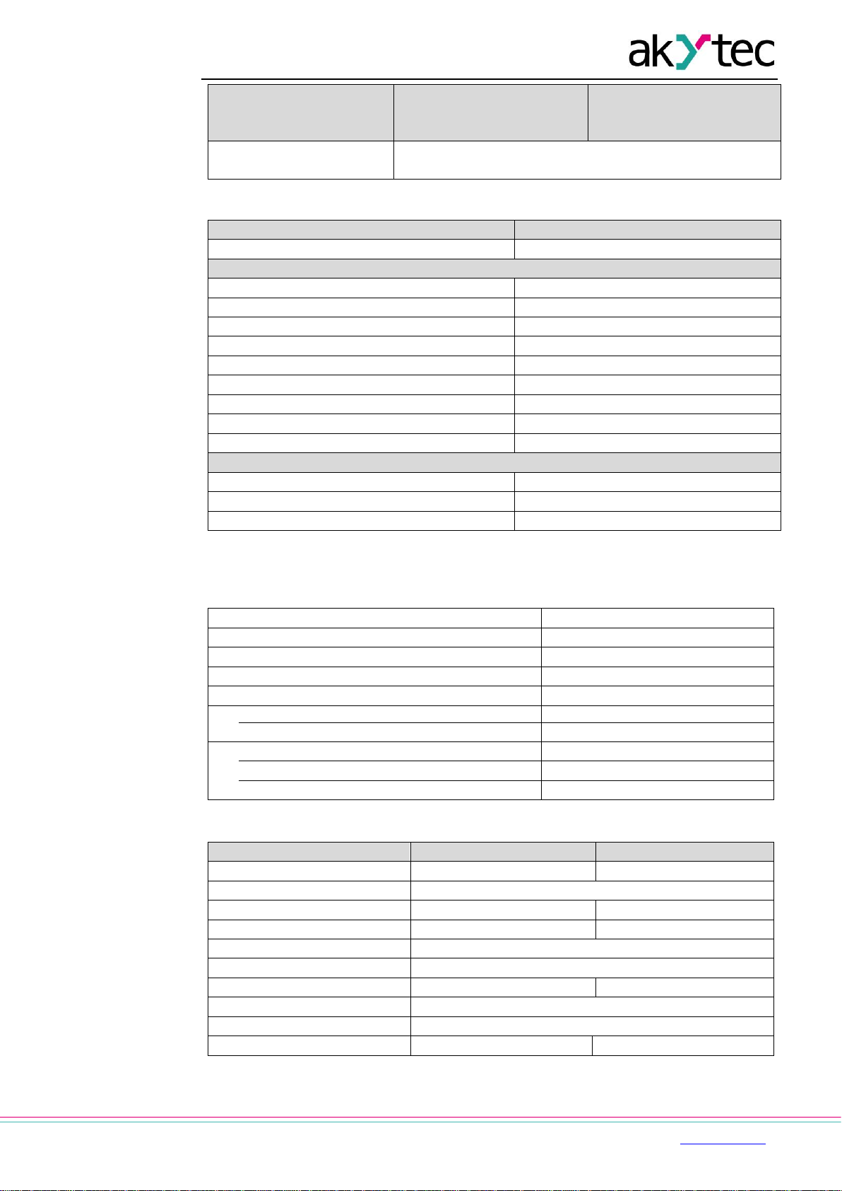
Table 2.2 Digital inputs
Device
230.1.x
230.2.x
230.4.x
24.1.x
24.2.x
24.4.x
Input signal
Switch contact
Switch contact
PNP with open collector
Digital signals -3…+30 VDC
Input voltage
230 V AC
24 V DC
Input voltage, max
264 V AC
30 V DC
Logical 1
159…264 V (0.75…1.5 mA)
15…30 V (5 mA)
Logical 0
0…40 V (0…0.5 mA)
-3…+5 V (0…1 mA)
Pulse length, min
50 ms
2 ms
Response time, max
100 ms
30 ms
Galvanic isolation
in groups of 4 (1-4, 5-8)
Test voltage between
input groups
1780 V
Page 7
Specifications
akYtec GmbH · Vahrenwalder Str. 269 A · 30179 Hannover · Germany Tel.: +49 (0) 511 16 59 672-0 · www.akytec.de
6
Device
230.1.x
230.2.x
230.4.x
24.1.x
24.2.x
24.4.x
Test voltage against
other circuits
2830 V
Table 2.3 Analog inputs
Device
x.2.x, x.4.x
Galvanic isolation
none
Analog mode
Input signal
0-10 V, 4-20 mA, 0-4000 ohm
Input voltage *
-36…+36 V
Input resistance (0-10 V)
61 kohm
Input resistance (4-20 mA)
121 ohm
Basic error
±0.5%
Temperature influence
±0.05%/10°C
Resolution
2.7 mV / 6 µA
ADC resolution
12 bit
Sampling time for 4 inputs, max
10 ms
Digital mode
Logic 1 **
0…10 V, adjustable
Logic 0 **
0…10 V, adjustable
Current at input voltage 15…30 V, max
5 mA
* If the voltage at one input is below -0.5 V, the accuracy for all inputs cannot be guaranteed.
** Parameter can be set in ALP Property Box using the option Input mode = digital.
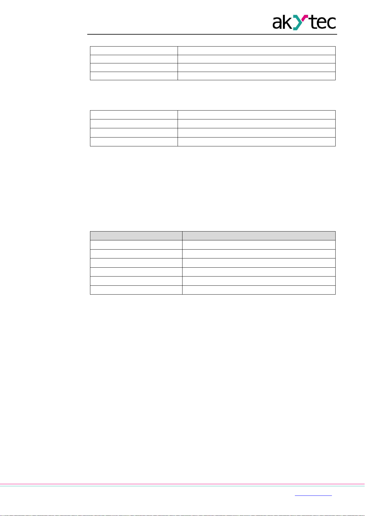
Table 2.4 Digital outputs
Type
relay (NO)
Switching capacity AC
5 A, 250 V (resistive load)
Switching capacity DC
3 A, 30 V
Minimum load current
10 mA (at 5 V DC)
Service life, electrical
3 A, 30 V DC
200,000 switching cycles
5 A, 250 V AC (resistive load)
100,000 switching cycles
Galvanic isolation
in groups of 2 (1-2, 3-4, 5-6, 7-8)
Test voltage between output groups
1780 V
Test voltage against other circuits
2830 V
Table 2.5 Analog outputs
Device
x.2.x
x.4.x
Auxiliary voltage
12…30 V DC
12…30 V DC
Quantity
2
Output signal
4-20 mA
0-10 V
Output load, max
1 kohm
2 kohm
Basic error, max
±0.5%
Temperature influence
±0.05%/10°C
Inductive load, max
50 µH
-
Signal conversion time
100 ms
DAC resolution
10 bit
Galvanic isolation
2830 V, individual
2830 V, in group
Page 8
Specifications
akYtec GmbH · Vahrenwalder Str. 269 A · 30179 Hannover · Germany Tel.: +49 (0) 511 16 59 672-0 · www.akytec.de
7
Table 2.6 Memory
ROM memory
128 kB
RAM memory
32 kB
Retain memory
1016 Byte
Network variable memory *
128 Byte
* The limitation applies only to the slave mode, in which all network variables are
automatically declared as retain.
Table 2.7 Real-time clock
Accuracy
±3 s/day (25°C)
Correction
-2.75…+5.5 min/month
Backup, min
8 years
Backup battery
CR2032
2.1 Environmental conditions
The device is designed for natural convection cooling. It should be taken into account when
choosing the installation site.
The following environment conditions must be observed:
clean, dry and controlled environment, low dust level
closed non-hazardous areas, free of corrosive or flammable gases
Table 2.8
Conditions
Permissible range
Ambient operating temperature
-20…+55°C
Storage temperature
-25…+55°C
Relative humidity
up to 80% (at +25°C, non-condensing)
Altitude
up to 2000 m above sea level
EMC immunity
conforms to IEC 61000-6-2
EMC emission
conforms to IEC 61000-6-4
Page 9
Installation
akYtec GmbH · Vahrenwalder Str. 269 A · 30179 Hannover · Germany Tel.: +49 (0) 511 16 59 672-0 · www.akytec.de
8
3 Installation
The relay is designed for DIN rail mounting. The environmental conditions from the section
2.1 must be observed. For the dimension drawing see Appendix. A
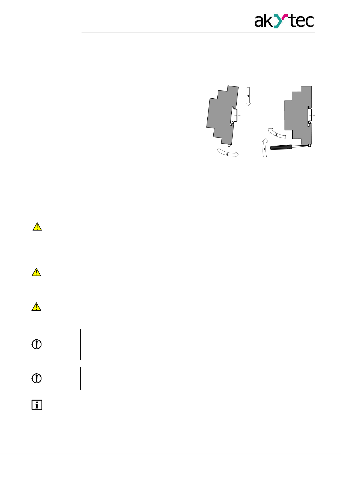
3.1 Mounting
Align the upper slide of the DIN rail
mounting groove with the DIN rail and
push it onto the rail.
Wire external connections in
accordance with sec. 3.2 using plug-in
terminal blocks (included).
Removal:
Take off the terminal blocks without
disconnecting the wires.
Insert a screwdriver into the eyelet of
the slide interlock, push it down and
remove the relay from the rail.
Fig. 3.1
3.2 Wiring
WARNING
Electric shock could kill or seriously injure.
All electrical connections must be performed by a fully qualified electrician.
Ensure that the mains voltage matches the voltage marked on the nameplate.
Ensure that the device is provided with its own power supply line and electric fuse.
Do not feed any external devices from the power contacts of the device.
Remove the terminal blocks only after powering off the device and all connected
equipment.
WARNING
The device must be powered off before connecting to peripheral devices, internal
bus or PC. Switch on the power supply only after the wiring of the device has been
completed.
WARNING
The program runs after transferring it to the relay. It is recommended to transfer the
program before wiring the relay.
Otherwise ensure that all peripheral devices are disconnected from relay outputs
before transferring the program.
NOTICE
Supply voltage for 24 VDC models may not exceed 30 V. Higher voltage can damage
the device.
If the supply voltage is lower than 19 V DC, the device cannot operate properly but
will not be damaged.
NOTICE
Signal cables should be routed separately or screened from the supply cables.
Shielded cable should be used for the signal lines to ensure compliance with the
EMC requirements.
NOTE
Before powering on, make sure that the device was stored at the specified ambient
temperature (-20 ... +55 °C) for at least 30 minutes.
─ For terminal assignment, see Tables 3.1, 3.2
─ For I/O electrical connections, see Fig. 3.2…3.7
─ For terminal blocks layouts, see app. B
Page 10
Installation
akYtec GmbH · Vahrenwalder Str. 269 A · 30179 Hannover · Germany Tel.: +49 (0) 511 16 59 672-0 · www.akytec.de
9
─ Maximum conductor cross-section is 0.75 mm²
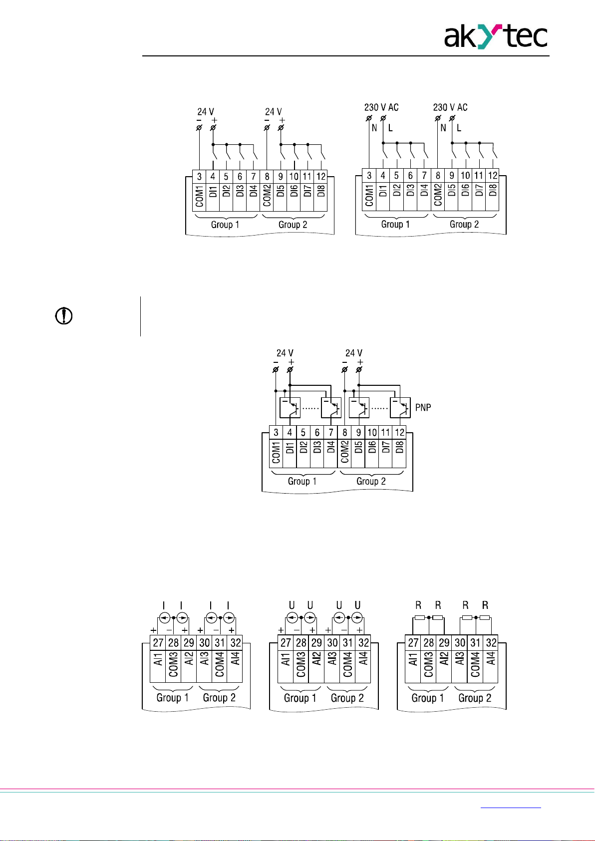
3.2.1 Inputs
a b
Fig. 3.2 Connection of switch contacts to digital inputs: a) 24.x.x, b) 230.x.x
NOTICE
230.x.x models
The digital inputs are divided into two groups, each of four inputs. All inputs must
be operated on the same phase. Different phases are not allowed.
Fig. 3.3 Connection of 3-wire sensors with PNP transistor outputs to digital inputs (24.x.x
only)
For 24.x.x models, it is permissible to connect sensors with switch contacts and transistor
outputs to digital inputs within the same input group.
If the galvanic isolation between inputs groups is not required, a common power supply,
including the integrated 24 VDC voltage source, can be used for both groups.
a b c
Fig. 3.4 Analog inputs: a) 4-20 mA, b) 0-10 V, c) 0-4000 ohm
Different sensors can be connected within a group. For example, AI1 can be configured as
digital and AI2 as analog 4-20 mA.
Page 11

Installation
akYtec GmbH · Vahrenwalder Str. 269 A · 30179 Hannover · Germany Tel.: +49 (0) 511 16 59 672-0 · www.akytec.de
10
3.2.2 Outputs
Fig. 3.5 Relay outputs
Fig. 3.6 Analog outputs 4-20 mA (x.2.x)
Fig. 3.7 Analog outputs 0-10 V (x.4.x)
NOTICE
The output voltage of an external voltage source may not exceed 30 V. Higher
voltage can damage the device.
For voltage supply of analog outputs 4-20 mA or 0-10 V, the integrated voltage source can
be used.
3.2.3 Terminal assignment
For terminal layouts see App. B.
Table 3.1 Terminal assignment
No.
Marking
Description
1
AC230V L / DC24V-
AC / DC power supply *
2
AC230V N / DC24V+
AC / DC power supply *
3
COM1
DI1...DI4 common contact
4
DI1
DI1 digital input
5
DI2
DI2 digital input
6
DI3
DI3 digital input
7
DI4
DI4 digital input
8
COM2
DI5...DI8 common contact
9
DI5
DI5 digital input
10
DI6
DI6 digital input
11
DI7
DI7 digital input
12
DI8
DI8 digital input
13
OUT 24V+
24 VDC integrated voltage source **
14
OUT 24V-
24 VDC integrated voltage source **
15
DO1
DO1 digital output
16
-
DO1...DO2 common contact
17
DO2
DO2 digital output
Page 12
Installation
akYtec GmbH · Vahrenwalder Str. 269 A · 30179 Hannover · Germany Tel.: +49 (0) 511 16 59 672-0 · www.akytec.de
11
No.
Marking
Description
18
DO3
DO3 digital output
19
-
DO3...DO4 common contact
20
DO4
DO4 digital output
21
DO5
DO5 digital output
22
-
DO5...DO6 common contact
23
DO6
DO6 digital output
24
DO7
DO7 digital output
25
-
DO7...DO8 common contact
26
DO8
DO8 digital output
27
AI1
AI1 analog input
28
COM3
AI1...AI2 common contact
29
AI2
AI2 analog input
30
AI3
AI3 analog input
31
COM4
AI3...AI4 common contact
32
AI4
Analog input AI4
33
RS-485 D-
RS485 Interface 1-
34
RS-485 D+
RS485 Interface 1+
35
RS-485 D-
RS485 Interface 2-
36
RS-485 D+
RS485 Interface 2+
37…40
see Table 3.2
* Depending on device model (230.x.x or 24.x.x)
** 230.x.x model only
Table 3.2 Terminals 37-40
No.
Marking
Description
x.2.2
37
АО1-
AO1 analog output (4-20 mA)
38
АО1+
39
АО2-
AO2 analog output (4-20 mA)
40
АО2+
x.4.2
37
V-
-24 VDC external voltage supply
38
V+
+24 VDC external voltage supply
39
АО1
AO1 analog output (0-10 V)
40
АО2
AO2 analog output (0-10 V)
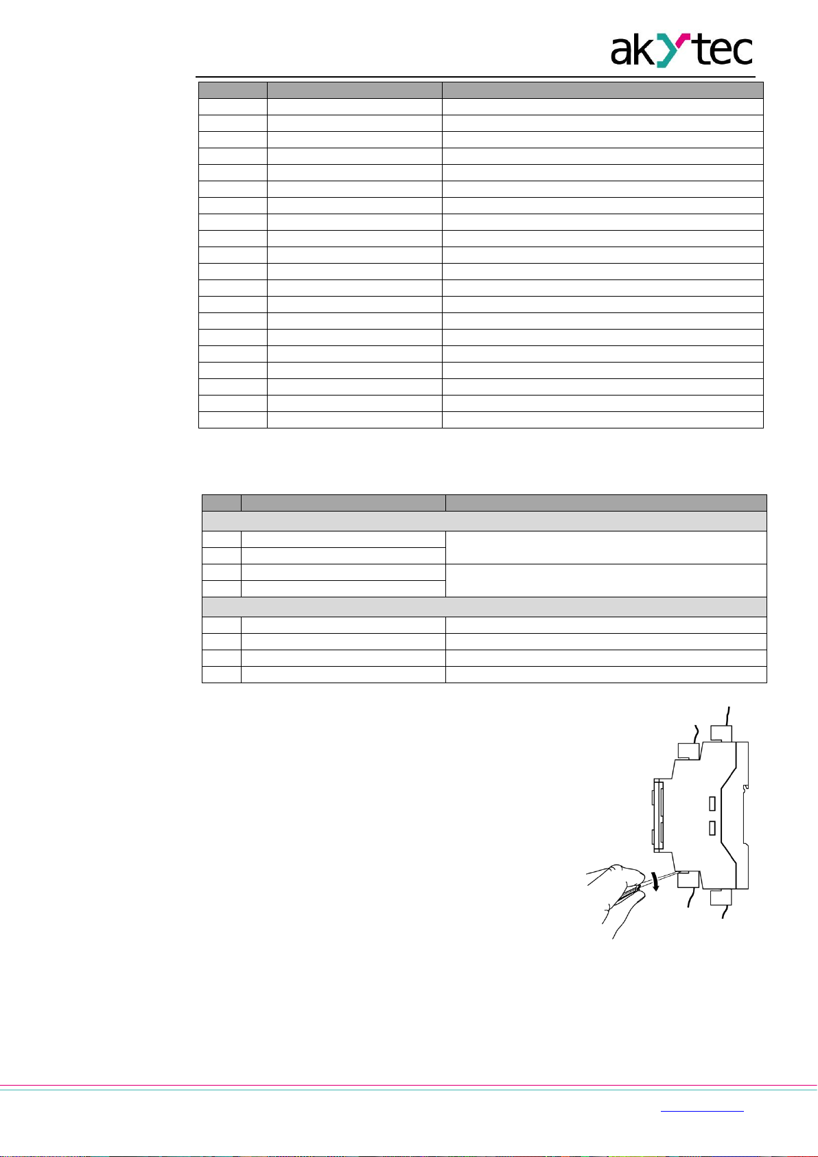
3.3 Quick replacement
PR200 is equipped with plug-in terminal blocks which enable
quick replacement of the device without disconnecting the
existing wiring (Fig. 3.8).
To replace the device:
power off all connected lines including power supply
remove the terminal blocks
replace the device
connect the terminal blocks with existing wiring to the
device
Fig. 3.8 Quick replacement
Page 13
Hardware resources
akYtec GmbH · Vahrenwalder Str. 269 A · 30179 Hannover · Germany Tel.: +49 (0) 511 16 59 672-0 · www.akytec.de
12
4 Hardware resources
To use all hardware resources in a program, the device must be configured. The
configuration is carried out in ALP and is transferred as a part of user project to the device
memory. The configuration parameters are stored in non-volatile memory of the device and
are safe when the device is powered off.
The device can also be configured with the function buttons via the system menu without
being connected to ALP (sect. 5.2). If some parameter has been changed this way, it has to
be taken from the device memory into the ALP project in order to keep the project
syncronized. Use Read button in the corresponding mask in the configuration window.
The following hardware can be configured:
Display
Clock
Interfaces (sect. 4.3)
Extension modules
Inputs (sect. 4.1)
Outputs (sect.4 2)
See ALP Help for detailed information about configuration.
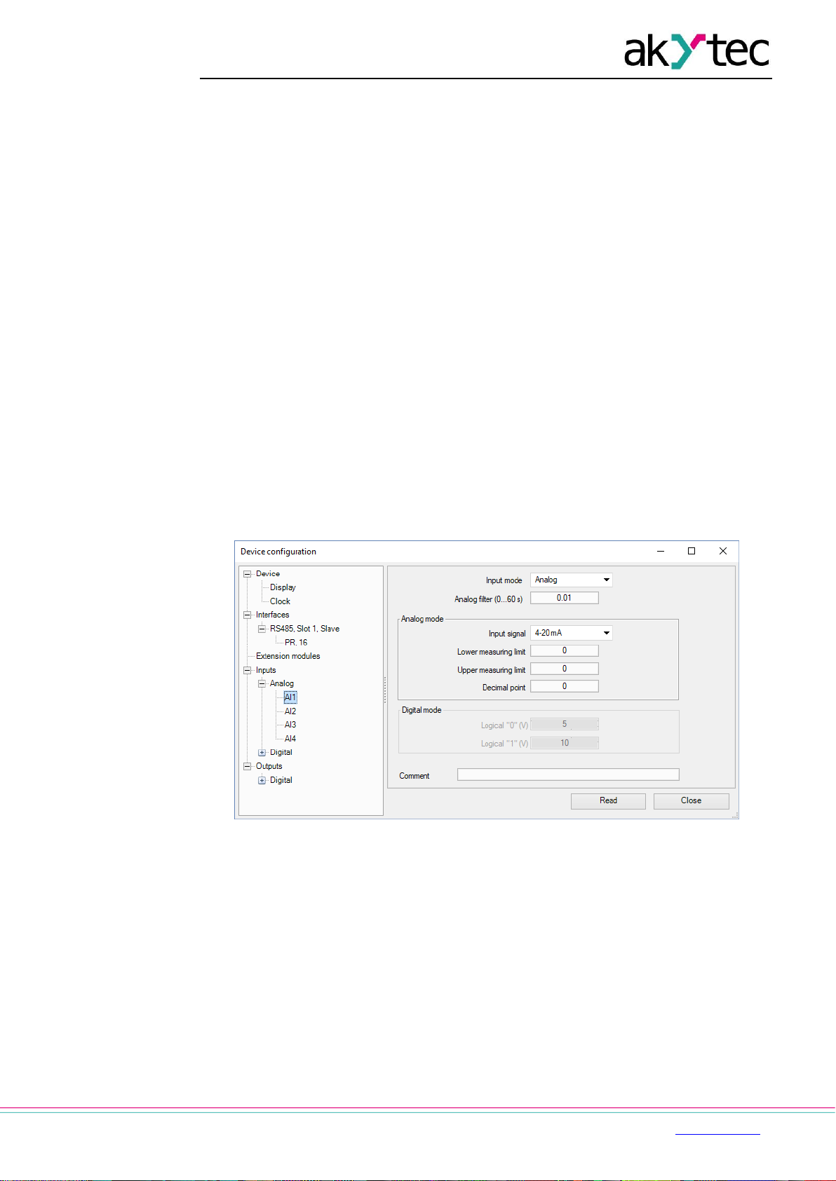
4.1 Analog inputs AI1…AI4
To configure analog inputs use the ALP menu item Device > Configuration. Open the node
Inputs > Analog in the open window Device configuration (Fig. 4.1) and select an analog
input.
Fig. 4.1 Analog input configuration
For quick access select an input in the circuit program and use Property Box (see Fig. 4.2) to
set the parameters. The parameter Input mode has to be set first.
Page 14

Hardware resources
akYtec GmbH · Vahrenwalder Str. 269 A · 30179 Hannover · Germany Tel.: +49 (0) 511 16 59 672-0 · www.akytec.de
13
Fig. 4.2 Property Box for analog input
See ALP Help for detailed information about analog input configuration.
4.1.1 Analog mode
Configurable parameters:
Input mode – select Analog
Filter – filter time constant (0…60 s)
Input signal – 4-20 mA, 0-10 V, 0-4000 ohm
Lower limit – lower measuring limit
Upper limit – upper measuring limit
Decimal places – parameter DP for Modbus request (Table 4.2). The parameter DP
has to be set to determine the accuracy, if the measured value is requested over
Modbus as integer.
If the type of input signal is selected, the input must be configured on the hardware side
using jumpers XP1…XP4 on the middle PCB in accordance with the selection.
The middle PCB is under the top PCB, but the last one does not need to be removed in this
case. The location of the jumpers on the PCB is shown in Fig. 4.3.
Jumper positions corresponding to the input signals are shown in Fig. 4.4.
All analog inputs are configured for 4-20 mA by default.
Fig. 4.3 Input jumpers on the middle PCB
WARNING
The voltage on some components on the circuit board can be dangerous. Direct
contact with the circuit board or penetration of a foreign body in the enclosure must
be avoided.
Page 15

Hardware resources
akYtec GmbH · Vahrenwalder Str. 269 A · 30179 Hannover · Germany Tel.: +49 (0) 511 16 59 672-0 · www.akytec.de
14
NOTICE
If the input signal does not correspond with the hardware configuration, the device
can be damaged. Check the positions of the jumpers XP1…XP4 before wiring.
To configure the input hardware:
– remove the front cover
– set the jumpers on the respective jumper block XP in accordance to the expected
input signal using a thin tool (e.g. tweezers)
– close the front cover.
Fig. 4.4 Input jumper positions
a) 0-10 V, b) 4-20 mA, c) digital mode, d) 0-4000 ohm
The lower and upper measuring limits must be set to scale the input signal.
Scaling is not available if the signal 0-4000 ohm is selected. In that case the measured value
is represented only in REAL32 format. The parameter Decimal places (DP) is not available
for 0-4000 ohm signal as well.
The resistance input is designed for 2 wire sensors only.
The effect of lead resistance can be compensated in the program.
4.1.2 Digital mode
Configurable parameters:
Input mode – select Digital
Filter – filter time constant (0…60 s)
Logical 0 – 0…10 V
Logical 1 – 0…10 V
The input operates as a comparator with parameters Logical 0 and Logical 1 which
determine the hysteresis and can be set in the range of 0…10 V (Fig. 4.5).
Fig. 4.5 Digital mode operation
4.1.3 Analog input filtering
The input filter stabilizes the input reading. The filter setting is a time constant representing
the time interval in which the signal reaches 0.63 of the measured value. It can be set within
the range of 0.01…60 s with the increment of 0.001 second for each input separately.
The greater the time constant, the higher the damping of the interference signal and the
slower the reaction to rapid changes in the input value.
4.2 Analog outputs AO1, AO2
The model x.2.x has two analog outputs 4-20 mA, x.4.x has two analog outputs 0-10 V.
Page 16

Hardware resources
akYtec GmbH · Vahrenwalder Str. 269 A · 30179 Hannover · Germany Tel.: +49 (0) 511 16 59 672-0 · www.akytec.de
15
To control an output, a value of type REAL32 within the range 0…1 has to be assigned to it
in the program.
When the value of 0.5 is applied to the output 4-20 mA, the output current will be 12 mA.
When the value of 0.5 is applied to the output 0-10 V, the output voltage will be 5 V.
See ALP Help for detailed information about analog output configuration.
4.3 RS485 interface
Up to two RS485 interface cards can be installed in the PR200 for communication via
Modbus RTU / ASCII protocol as master or slave.
The interface card is configured as a slave by default. To use the interface as a master, set
the jumpers XP4 and XP5 on the interface card in accordance with the Fig. 4.6:
set the both jumpers to M position
configure the interface using the ALP menu item Device > Configuration
Fig. 4.6 Interface card jumper positions: master (a), slave (b)
See ALP Help for detailed information about RS485 interface configuration. The parameters
can also be changed via system menu (sect. 5.2).
4.3.1 Slave mode
Available network functions:
read digital I/O status
read analog I/O value
read / write network variables
read / write Real-Time Clock data
Corresponding Modbus registers are listed in Tab. 4.1.
Modbus RTU and Modbus ASCII protocols are supported, with automatic protocol detection.
To add an interface, use the context menu of the node Interfaces in the configuration tree
and select Add interface > RS485 (Fig. 4.7). The new interface is a slave by default.
Use the context menu of the new interface to add a master device (Fig 4.8).
Define the name and the Modbus address for the master.
Page 17

Hardware resources
akYtec GmbH · Vahrenwalder Str. 269 A · 30179 Hannover · Germany Tel.: +49 (0) 511 16 59 672-0 · www.akytec.de
16
Fig. 4.7 Slave configuration in Slave mode
Following parameters can be set for Master:
Name – device name in the configuration tree
Address – device address in the Modbus network.
Change register order – reverse the register order according to the method of
storing variables in device memory
Change byte order – reverse the byte order in a register according to the method of
storing variables in device memory
See ALP Help for further details about configuration in the Slave mode.
To create a variable for polling click the icon.
To delete the selected variable click the icon.
Fig. 4.8 Master configuration in Slave mode
Page 18

Hardware resources
akYtec GmbH · Vahrenwalder Str. 269 A · 30179 Hannover · Germany Tel.: +49 (0) 511 16 59 672-0 · www.akytec.de
17
Table 4.1 Modbus registers
Model
Parameter
Data
type
Address (hex)
Modbus
function
Inputs
All
DI1...DI8 input status
BOOL
0x1000 – 0x1007
0x01, 0x02
UINT16
0x0100
0x03, 0x04
x.2.x
x.4.x
AI1 measured value REAL
REAL32
0x0B00, 0х0B01
0x03, 0x04
AI2 measured value REAL
REAL32
0x0B02, 0х0B03
0x03, 0x04
AI3 measured value REAL
REAL32
0x0B04, 0х0B05
0x03, 0x04
AI4 measured value REAL
REAL32
0x0B06, 0х0B07
0x03, 0x04
AI1 measured value UINT *
UINT16
0x0B80
0x03, 0x04
AI2 measured value UINT *
UINT16
0x0B81
0x03, 0x04
AI3 measured value UINT *
UINT16
0x0B82
0x03, 0x04
AI4 measured value UINT *
UINT16
0x0B83
0x03, 0x04
AI1 decimal point (DP) UINT *
UINT16
0x0BC0
0x03, 0x04
AI2 decimal point (DP) UINT *
UINT16
0x0BC1
0x03, 0x04
AI3 decimal point (DP) UINT *
UINT16
0x0BC2
0x03, 0x04
AI4 decimal point (DP) UINT *
UINT16
0x0BC3
0x03, 0x04
AI1 input status (digital mode)
BOOL
0xB800
0x01, 0x02
AI2 input status (digital mode)
BOOL
0xB810
0x01, 0x02
AI3 input status (digital mode)
BOOL
0xB820
0x01, 0x02
AI4 input status (digital mode)
BOOL
0xB830
0x01, 0x02
Outputs
x.1.x
DO1...DO6, F1, F2 output status
BOOL
0x0000 – 0x0007
0x01, 0x02
UINT16
0x0000
0x03, 0x04
x.2.x
x.4.x
DO1...DO8, F1, F2 output status
BOOL
0x0000 – 0x0009
0x01, 0x02
UINT16
0x0000
0x03, 0x04
x.2.x
x.4.x
AO1 output value (0…1)
REAL32
0х0A00, 0х0A01
0x03, 0x04
AO2 output value (0…1)
REAL32
0х0A02, 0х0A03
0x03, 0x04
AO1 output value (0…10000)
UINT16
0x0A80
0x03, 0x04
AO2 output value (0…10000)
UINT16
0x0A81
0x03, 0x04
All
Network variables
BOOL
0x2000 – 0x23F0
0x01, 0x02,
0x05, 0x0F
UINT16
0x0200 – 0x023F
0x03, 0x04,
0x06, 0x10
Real-time clock
All
Seconds
UINT16
0x0400
0x03, 0x04,
0x06, 0x10
Minutes
UINT16
0x0401
0x03, 0x04,
0x06, 0x10
Hours
UINT16
0x0402
0x03, 0x04,
0x06, 0x10
Day
UINT16
0x0403
0x03, 0x04,
0x06, 0x10
Month
UINT16
0x0404
0x03, 0x04,
0x06, 0x10
Year
UINT16
0x0405
0x03, 0x04,
0x06, 0x10
Weekday
UINT16
0x0406
0x03, 0x04
Week of month
UINT16
0x0407
0x03, 0x04
Calendar week
UINT16
0x0408
0x03, 0x04
* AI1 measured value UINT = AI1 measured value REAL * 10 DP (sect. 4.1.1)
For outputs DP = 4 (constant)
4.3.2 Master mode
There can be only one master in Modbus network.
Page 19

Hardware resources
akYtec GmbH · Vahrenwalder Str. 269 A · 30179 Hannover · Germany Tel.: +49 (0) 511 16 59 672-0 · www.akytec.de
18
PR200 as a master can control up to 16 slaves over one RS485 interface. Each slave can
maintain up to 256 variables. To use the same name and the same address for different
slaves is allowed.
To add an interface, use the context menu of the node Interfaces in the configuration tree
and select Add interface > RS485 (Fig. 4.9). Change the mode to Master in the right
window part.
Fig. 4.9 Master configuration in Master mode
Add the required number of slave devices using the context menu of the new interface (Fig
4.10). Define the name and the Modbus address for each slave.
Following parameters can be set for the slave:
Name – device name in the configuration tree
Address – device address in the Modbus network.
Polling cycle – time between requests (0…65535 ms)
Retries – number of request retries if no reply (0…255)
Timeout – maximum time to wait for reply (0…65535 ms)
Status variable – status of slave device (BOOL variable)
Start query – start / stop polling (BOOL variable)
Change register order – reverse the register order according to the method of
storing variables in the device memory
Change byte order – reverse the byte order in a register according to the method of
storing variables in the device memory
See ALP Help for further details about configuration in Master mode.
To create a variable to be requested click th e icon (Fig. 4.10).
To delete the selected variable click the icon.
The reading request is trigged by the Polling cycle by default. Optionally it can be triggered
by changing a variable of type BOOL.
The writing request is triggered by change of parameter value. Optionally it can be triggered
by changing. a variable of type BOOL.
Page 20

Hardware resources
akYtec GmbH · Vahrenwalder Str. 269 A · 30179 Hannover · Germany Tel.: +49 (0) 511 16 59 672-0 · www.akytec.de
19
Fig. 4.10 Slave configuration in Master mode
Note:
If PR200 is a master in the Modbus network, it is necessary to observe the following rules to
speed up the polling of all slaves:
If one or more slaves are disconnected or not accessible, it is recommended to block
the polling of these slaves in the program using the parameter Start query or to
minimize the parameter Timeout for these slaves. Otherwise, the response time is
significantly increased with the number of unavailable slaves and the sum of time-
outs.
When setting the master parameter Interval between requests (Fig. 4.9), the
number of slaves and the total number of requests must be taken into account. If the
total polling takes actually longer than the set value, this parameter will be ignored.
4.4 Service modes
To switch the device to one of the two service modes, use the jumpers XP2 and XP3 on the
top PCB (Fig. 4.11).
WARNING
The voltage on some components on the circuit board can be dangerous. Direct
contact with the circuit board or penetration of a foreign body in the enclosure must
be avoided.
NOTICE
Do not set the jumpers XP2 and XP3 at the same time, otherwise the device can be
damaged.
Page 21

Hardware resources
akYtec GmbH · Vahrenwalder Str. 269 A · 30179 Hannover · Germany Tel.: +49 (0) 511 16 59 672-0 · www.akytec.de
20
Fig. 4.11 Service mode jumpers
RUN-STOP mode
In RUN-STOP mode the execution of the program is interrupted. It can be useful if the
system menu is unavailable, e.g. if the corrupted program leads to device malfunction.
Set XP2 jumper to activate RUN-STOP mode.
In RUN-STOP mode, a new program can be uploaded to the device.
In this mode the device can be used only as a slave and the network variables are disabled.
DOWN mode
DOWN mode is necessary for troubleshooting if a firmware update was unsuccessful (power
outage, communication errors etc.). In this mode the firmware update can be forced. See
ALP Help for further details about firmware update.
Set XP3 jumper to activate DOWN mode.
Page 22

Operation
akYtec GmbH · Vahrenwalder Str. 269 A · 30179 Hannover · Germany Tel.: +49 (0) 511 16 59 672-0 · www.akytec.de
21
5 Operation
Once the program has been transferred to the non-volatile memory, the relay restarts. On
startup, the relay performs a self-test. If it is unsuccessful, the relay will switch to error mode
(sect. 5.1). Otherwise, the program will run (Fig. 5.1)
WARNING
The program is executed after it has been transferred to the relay. It is
recommended to transfer the program before wiring the relay.
Otherwise ensure that all external devices are disconnected from outputs before
transferring the program.
NOTE
Before starting
Before switching on, make sure that the device was stored at the specified ambient
temperature (-20 ... +55 °C) for at least 30 minutes.
Operation of the device is cycle oriented:
1. operational readiness test
2. input process image update
3. program execution for one cycle
4. output process image update
5. back to 1.
Fig. 5.1 Operating sequence
5.1 Error mode
In the error mode, the program is stopped until the error cause is eliminated.
Table 5.1 Error indication
Indication
Cause
Remedy
LOGIC Program
INVALID
Invalid program
Repair the program in ALP
LOGIC Program
MEMORY ERROR
Retain variables cannot be read
LOGIC Program
BLOCKED
RUN-STOP mode is activated,
program stopped (sect. 4.4)
Remove the RUN-STOP jumper
and restart the device
LED F2 lit
Firmware damaged
Update the firmware or contact
the service center
LED F2 blinks
LOGIC Program
STOPPED
Program stopped
Start the program using system
menu and restart the device
5.2 System menu
The system menu allows you to view the most important parameters of the device and
perform a quick configuration without connection to ALP.
The program can be interrupted by using the system menu item Device > Program. Select
Stop program to stop the program execution or Run program to start it. After changing the
setting, the device must be restarted for the change to take effect. When the program is
interrupted, all parameters except the network variables are available via via system menu
and Modbus network in Slave mode.
Page 23

Operation
akYtec GmbH · Vahrenwalder Str. 269 A · 30179 Hannover · Germany Tel.: +49 (0) 511 16 59 672-0 · www.akytec.de
22
Press button for 3 seconds to access the menu.
Press button for 3 seconds to exit the menu.
The menu can be password protected. The password can be set and changed in ALP or
using the system menu. If the password is lost, it can be changed by loading a new project to
the device.
5.2.1 Display navigation
The display can be used in view or edit mode. The edit mode is only for editable display
elements available.
View mode
To move between lines use and buttons.
To enter the selected level, use button, to exit the level, use button.
Edit mode
Use button to enter the edit mode from the current display. The first editable element
starts flashing.
Use and buttons to change the parameter.
To move between characters, use the button combinations:
+ – one character to the left
+ – one character to the right.
To save the new value and exit the edit mode, use .
To reset the parameter to its previous value and exit the edit mode, use button.
To save the new value staying in the edit mode, use button. The next editable parameter
will be displayed selected.
Next time, when the edit mode is activated, the last changed parameter will be displayed.
If a parameter has been changed in the edit mode, it must be transferred to the ALP project
using the Read button in the corresponding dialog window.
Page 24

Operation
akYtec GmbH · Vahrenwalder Str. 269 A · 30179 Hannover · Germany Tel.: +49 (0) 511 16 59 672-0 · www.akytec.de
23
5.2.2 Menu structure
Fig. 5.2 System menu
Inputs
Digital
o I/O state – status of digital inputs displayed as a bitmask: 1/0 (ON/OFF).
The first bit in the mask corresponds to the input DI1.
o Filter – debouncing filter time constant (0…255 ms), displayed in pairs. Use
/ buttons to navigate between pairs.
Analog
o I/O state – status of analog inputs as scaled measured values of REAL32
type, displayed in pairs. Use / buttons to navigate between pairs.
o Sensor – type of the input signal
ALT
OK
OK
OK
OK
OK
OK
ESC
OK
OK
OK
OK
OK
OK
OK
OK
OK
OK
OK
OK
OK
OK
OK
OK
Page 25

Operation
akYtec GmbH · Vahrenwalder Str. 269 A · 30179 Hannover · Germany Tel.: +49 (0) 511 16 59 672-0 · www.akytec.de
24
o Filter – analog filter time constant within the range of 0.01…60 s with the
increment of 0.001 s, displayed in pairs. Use / buttons to navigate
between pairs.
o Scale – lower and upper limits for input signal scaling. Use /
buttons to navigate between inputs.
Outputs
Digital
o I/O state – status of digital outputs, including LED indicators F1/F2,
displayed as a bitmask: 1/0 (ON/OFF). The first bit in the mask corresponds
to the output DO1, the last bit in the mask corresponds to the indicator F2.
Analog
o I/O state – status of analog outputs as REAL32 values within the range of
0…1, displayed in pairs. Use / buttons to navigate between pairs.
Interfaces
Interface configuration depends on the interface mode, Master or Slave. Select the interface
to view its parameters (sect. 4.3).
Slave mode
o Settings
Baud rate – Data bits – Parity – Stop bits
o Protocol
Interface mode / Address – master address
Master mode
o Settings
Baud rate – Data bits – Parity – Stop bits
o Protocol
Interface mode / Devices – list of slaves from the project
Address – slave address
Period – Query cycle (ms)
Timeout – Time-out (ms)
Attemts – Retries, max.
Pause – Interval between requests (ms)
Modules
This menu item contains the information about the extension modules connected to the base
device. The item is hidden if there are no modules connected.
Fig. 5.3 Extension module connection
Password
Password can be set or changed (sect. 5.2).
5.3 Display programming
The display can be programmed using one or more display forms. To switch between two
display forms, jump conditions have to be created. Jump condition can be an event of a
Page 26

Operation
akYtec GmbH · Vahrenwalder Str. 269 A · 30179 Hannover · Germany Tel.: +49 (0) 511 16 59 672-0 · www.akytec.de
25
function button or of a variable. For further details about display programming, see ALP
Help.
For display navigation, see section 5.2.1.
When assigning а jump condition to a function button, don't forget that the user function of
the button has a higher priority than its system function, i.e. and buttons cannot be
used to scroll the lines inside a display if they are used as the jump condition for it.
Page 27

Maintenance
akYtec GmbH · Vahrenwalder Str. 269 A · 30179 Hannover · Germany Tel.: +49 (0) 511 16 59 672-0 · www.akytec.de
26
6 Maintenance
The maintenance includes:
– cleaning of the housing and terminal blocks from dust, dirt and debris
– check the device fastening
– checking the wiring (connecting leads, fastenings, mechanical damage)
NOTICE
The device should be cleaned with a damp cloth only. No abrasives or solventcontaining cleaners may be used. During maintenance, observe the safety
instructions in the section "Installation".
Page 28

Transportation and storage
akYtec GmbH · Vahrenwalder Str. 269 A · 30179 Hannover · Germany Tel.: +49 (0) 511 16 59 672-0 · www.akytec.de
27
7 Transportation and storage
Pack the device in such a way as to protect it reliably against impact for storage and
transportation. The original packaging provides optimum protection.
If the device is not taken immediately after delivery into operation, it must be carefully stored
at a protected location. The device should not be stored in an atmosphere with chemically
active substances.
Permitted storage temperature: -25...+55 °C
NOTICE
The device may have been damaged during transportation.
Check the device for transport damage and completeness!
Report the transport damage immediately to the shipper and akYtec GmbH!
Page 29

Scope of delivery
akYtec GmbH · Vahrenwalder Str. 269 A · 30179 Hannover · Germany Tel.: +49 (0) 511 16 59 672-0 · www.akytec.de
28
8 Scope of delivery
PR200 1
Short guide 1
USB cable 1
Terminal blocks (set) 1
Coding elements (set) 1
USB stick with software and documentation 1
NOTE
The manufacturer reserves the right to make changes to the scope of delivery.
Page 30

Appendix А. Dimensions
akYtec GmbH · Vahrenwalder Str. 269 A · 30179 Hannover · Germany Tel.: +49 (0) 511 16 59 672-0 · www.akytec.de
29
Appendix А. Dimensions
Fig. A.1 Dimensions without terminal blocks
Page 31

Appendix B. Terminal layouts
akYtec GmbH · Vahrenwalder Str. 269 A · 30179 Hannover · Germany Tel.: +49 (0) 511 16 59 672-0 · www.akytec.de
30
Appendix B. Terminal layouts
Fig. B.1 PR200-230.1.2
Fig. B.2 PR200-230.2.2
Page 32

Appendix B. Terminal layouts
akYtec GmbH · Vahrenwalder Str. 269 A · 30179 Hannover · Germany Tel.: +49 (0) 511 16 59 672-0 · www.akytec.de
31
Fig. B.3 PR200-230.4.2
Fig. B.4 PR200-24.1.2
Page 33

Appendix B. Terminal layouts
akYtec GmbH · Vahrenwalder Str. 269 A · 30179 Hannover · Germany Tel.: +49 (0) 511 16 59 672-0 · www.akytec.de
32
Fig. B.5 PR200-24.2.2
Fig. B.6 PR200-24.4.2
Page 34

Appendix C. Galvanic isolation
akYtec GmbH · Vahrenwalder Str. 269 A · 30179 Hannover · Germany Tel.: +49 (0) 511 16 59 672-0 · www.akytec.de
33
Appendix C. Galvanic isolation
Fig. C.1 PR200-230.1.x galvanic isolation
Fig. C.2 PR200-230.2.x galvanic isolation
Fig. C.3 PR200-230.4.x galvanic isolation
Fig. C.4 PR200-24.1.x galvanic isolation
Page 35

Appendix C. Galvanic isolation
akYtec GmbH · Vahrenwalder Str. 269 A · 30179 Hannover · Germany Tel.: +49 (0) 511 16 59 672-0 · www.akytec.de
34
Fig. C.5 PR200-24.2.x galvanic isolation
Fig. C.6 PR200-24.4.x galvanic isolation
Page 36

Appendix D. Circuit diagrams
akYtec GmbH · Vahrenwalder Str. 269 A · 30179 Hannover · Germany Tel.: +49 (0) 511 16 59 672-0 · www.akytec.de
35
Appendix D. Circuit diagrams
Fig. D.1 PR200-230.x.x digital input circuit diagram
Fig. D.2 PR200-24.x.x digital input circuit diagram
Fig. D.3 Analog input circuit diagram
Page 37

Appendix E. Calibration
akYtec GmbH · Vahrenwalder Str. 269 A · 30179 Hannover · Germany Tel.: +49 (0) 511 16 59 672-0 · www.akytec.de
36
Appendix E. Calibration
E.1 General
If the accuracy of the input or output of the module is no longer in accordance with the
specification, it can be calibrated.
NOTICE
Ensure a reliable power supply to the device during the calibration. If it fails, the
calibration should be repeated.
– Each analog input and output has its own calibration coefficients for each sensor
type.
– The calibration is performed using a reference signal source connected to the device
input or output.
– The calibration coefficients are calculated based of the ratio between the current
input signal and the reference signal and stored in the non-volatile device memory.
– If the calculated coefficients go beyond the permissible limits, a message about the
error cause will be displayed.
E.2 Input
Input signals: 4-20 mA, 0-10 V, 0-4000 ohm
1. Connect the reference signal source of accuracy class at least
0.05 to the input (Fig. E.1).
2. Connect the basic device to the PC.
3. Switch on the device power supply.
4. Start ALP and select the menu item Device > Calibration to
start the calibration tool.
5. Select the device model in the open dialog window.
6. Select Analog inputs as calibration target (Fig. E.2).
Fig. E.2
7. Select the type of input signal and set the other calibration
parameters (Fig. E.3).
o Set the three points for calibration curve and the filter
time constant.The greater the filter time constant, the
longer the calibration process will take, but the more
precise calibration will be achieved.
o Select the input to calibrate. If you select All, all inputs
will be calibrated sequentially, therefore the
appropriate reference signal has to be applied to all
inputs.
Fig. E.1
Page 38

Appendix E. Calibration
akYtec GmbH · Vahrenwalder Str. 269 A · 30179 Hannover · Germany Tel.: +49 (0) 511 16 59 672-0 · www.akytec.de
37
Fig. E.3
8. Click Next to continue and follow the instructions.
Click the item Reset settings to use the default calibration settings.
E.3 Output 4-20 mA
1. Connect an auxiliary voltage source, a measuring
device of resolution 0.001 V and a reference
resistance box of accuracy class at least 0.05 to the
output (Fig. E.4).
2. Ensure the supply voltage is within the range 15…28
V.
3. Set the reference resistance box to 500 ohm.
4. Connect the device to the PC.
5. Switch on the device power supply.
6. Start ALP and select the menu item Device >
Calibration to start the calibration tool.
7. Select the device model in the open dialog window.
8. Select Analog outputs as calibration target (Fig. E.2).
9. Calculate the output current from the measured output
voltage and the set resistance; enter the result in the
input field (Fig. E.5).
10. Click Next to continue and follow the instructions.
Fig. E.4
Fig. E.5
E.4 Output 0-10 V
1. Connect a reference voltage source and a measuring device of accuracy class at least
0.05 to the output (Fig. E.6).
Page 39

Appendix E. Calibration
akYtec GmbH · Vahrenwalder Str. 269 A · 30179 Hannover · Germany Tel.: +49 (0) 511 16 59 672-0 · www.akytec.de
38
Fig. E.6
2. Connect the device to the PC.
3. Switch on the device power supply.
4. Start ALP and select the menu item Device > Calibration to start the calibration tool.
5. Select the device model in the open dialog window.
6. Select Analog outputs as calibration target (Fig. E.2).
7. Enter the measured output voltage in the input field (Fig. E.5).
8. Click Next to continue and follow the instructions.
Page 40

Appendix F. Battery replacement
akYtec GmbH · Vahrenwalder Str. 269 A · 30179 Hannover · Germany Tel.: +49 (0) 511 16 59 672-0 · www.akytec.de
39
Appendix F. Battery replacement
WARNING
Dangerous voltage
The voltage on some components of the circuit board can be dangerous. Direct
contact with the circuit board or penetration of a foreign body in the enclosure must
be avoided.
1. Remove the front cover with the keypad (Fig. F.1)
2. Lever the top PCB from the side of the USB connector with a screwdriver and
carefully release it from the pin connectors of the middle PCB. (Fig. G.2).
3. Turn over the released top PCB, lever the CR2032 battery with the screwdriver and
pull out from the nest (Fig. F.3).
4. Install a new battery
5. Perform the disassemble operations in reverse order to assemble the device.
Fig. F.1 Front cover removing
Fig. F.2 Top PCB removing
Page 41

Appendix F. Battery replacement
akYtec GmbH · Vahrenwalder Str. 269 A · 30179 Hannover · Germany Tel.: +49 (0) 511 16 59 672-0 · www.akytec.de
40
Fig. F.3 Back side view of the top PCB
Page 42

Appendix G. Interface card installation
akYtec GmbH · Vahrenwalder Str. 269 A · 30179 Hannover · Germany Tel.: +49 (0) 511 16 59 672-0 · www.akytec.de
41
Appendix G. Interface card installation
WARNING
Dangerous voltage
The voltage on some components of the circuit board can be dangerous. Direct
contact with the circuit board or penetration of a foreign body in the enclosure must be
avoided.
1. Remove the front cover with the keypad (Fig. G.1).
2. Lever the top PCB from the side of the USB connector with a screwdriver and
carefully release it from the pin connectors of the middle PCB (Fig. F.2, G.1a).
3. Cut an opening in the front cover for the network connection and fix the card on the
mounting pins (Fig. G.1b).
4. Assemble in reverse order.
a b
Fig. G.1
 Loading...