

Page 1

akYtec GmbH · Vahrenwalder Str. 269 A · 30179 Hannover · Germany · Tel.: +49 (0) 511 16 59 672-0 · www.akytec.de
ITP15
LED Bargraph Indicator
User guide
ITP15_2019.12_48199_EN
© All rights reserved
Subject to technical changes and misprints
Page 2

akYtec GmbH · Vahrenwalder Str. 269 A · 30179 Hannover · Germany · Tel.: +49 (0) 511 16 59 672-0 · www.akytec.de
1
Contents
1 Overview ........................................................................................................................................................ 2
2 Technical data ............................................................................................................................................... 2
2.1 Galvanic isolation ..................................................................................................................................... 2
2.2 Environmental conditions ....................................................................................................................... 2
3 Intended use .................................................................................................................................................. 3
4 Functions ....................................................................................................................................................... 3
5 Installation ..................................................................................................................................................... 3
5.1 Wiring ......................................................................................................................................................... 3
5.1.1 Input .................................................................................................................................................. 4
5.1.2 Output ............................................................................................................................................... 4
6 Configuration................................................................................................................................................. 5
6.1 Alarm limits ............................................................................................................................................... 6
7. Operation ....................................................................................................................................................... 7
8. Maintenance .................................................................................................................................................. 8
9. Transportation and storage ......................................................................................................................... 8
10. Scope of delivery ...................................................................................................................................... 9
Appendix A. Dimensions .................................................................................................................................... 9
Page 3

akYtec GmbH · Vahrenwalder Str. 269 A · 30179 Hannover · Germany Tel.: +49 (0) 511 16 59 672-0 · www.akytec.de
2
1 Overview
ITP15 is a universally applicable process indicator. It is designed for visualizing percentage
reading of process parameter and can be used with various standard DC current or voltage
signals. The device requires 24V DC auxiliary voltage.
2 Technical data
Table 2.1 Technical data
Parameter
Value
Power supply
24 (10…30) V DC
Power consumption, max.
1 W
Input
1
Input signal
0-20 mA, 4-20 mA, 0-10 V, 2-10 V
Sampling time
0.3 s
Accuracy
± 2% FS
Input resistance
0-20 mA, 4-20 mA
≤ 115 ohm
0-10 V, 2-10 V
≥ 250 kohm
Output
1
Type
NPN transistor
Loading capacity
200 mA, 42 V DC
Display
LED, 10 segments, 2 colors (red/green)
Display hysteresis
1%
Display events
signal < 0%
signal = 0%
0% < signal < 100%
signal = 100%
signal > 100%
fault
Enclosure
for panel mounting, horizontal or vertical
Dimensions
48 x 26 x 65 mm
Weight, max
approx. 30 g
2.1 Galvanic isolation
The ITP15 has three potential groups:
Power supply 24 V DC
Analog input
Digital output
Galvanic isolation from each group to enclosure 500 V
Galvanic isolation between groups 500 V
2.2 Environmental conditions
The device is designed for natural convection cooling. It should be taken into account when
choosing the installation site.
The following environment conditions must be observed:
clean, dry and controlled environment, low dust level
closed non-hazardous areas, free of corrosive or flammable gases
Table 2.3 Environmental conditions
Conditions
Permissible range
Ambient temperature
-40…+60 °C
Storage temperature
-25…+55 °C
IP Code
front IP65, rear IP20
Protection class
III
Relative humidity
up to 80% (at +35°C, non-condensing)
Page 4

akYtec GmbH · Vahrenwalder Str. 269 A · 30179 Hannover · Germany Tel.: +49 (0) 511 16 59 672-0 · www.akytec.de
3
3 Intended use
The device may only be used in the manner described in this user guide, properly installed
and in accordance with the specification. Damages caused by disregarding the instructions
of this manual are without liability. Non-observance of the safety guidelines may result in
damage to the device and injury to personal.
Improper use
Any other use is considered improper. Especially to note:
The device may not be used for medical devices that sustain, monitor or otherwise affect
human life or health.
The device may not be used if the environmental conditions (temperature, humidity etc.)
are not within the limits indicated in the specification.
The device may not be used in potentially explosive environment or in an atmosphere
with chemically active substances.
4 Functions
Displays process value
Displays signal overrange
Adjustable alarm limits
Configurable output signal
Displays error when sensor break or short circuit.
5 Installation
CAUTION
Improper installation can cause serious or minor injuries and damage the device.
Installation must be performed only by fully qualified personnel.
The device is designed for horizontal or vertical panel mounting in a borehole of Ø22.5 mm
(see Appendix A for dimensional drawings).
Carefully position the supplied gasket on the display rear surface. Insert the cylindrical body
of the device into the borehole and tighten the nut from the rear side of the panel.
5.1 Wiring
CAUTION
Switch on the power supply only after the wiring of the device has been completely
performed
►
NOTICE
Switch off the device before checking the sensor and connection lines.
For circuit integrity check use only the measuring device with the output voltage max.
4.5 V to prevent the device damage. Disconnect the sensor in case of higher voltage.
►
NOTICE
Signal cables should be routed separately or screened from the supply cables.
Only a shielded cable may be used for signal lines.
Fig. 5.1 Wire preparation
Fig. 5.2 Connecting the wire to the terminal
Do not use wire end ferrules to connect
stranded wires.
To connect fine-stranded wire, tin the wire
end.
To connect solid wire, push the wire into the
terminal.
To connect stranded wire, press the release
lever and push the wire into the terminal.
Page 5

akYtec GmbH · Vahrenwalder Str. 269 A · 30179 Hannover · Germany Tel.: +49 (0) 511 16 59 672-0 · www.akytec.de
4
Fig. 5.3 Disconnecting the wire Fig. 5.4 Mounting
Press the release lever to free the wire.
– The electrical connections are shown in Fig. 5.5-5.6 and the terminal assignments in
Table 5.1.
– Connect the power supply to the terminals 24V+ / 24V-.
– Ensure that the device is provided with its own power supply line and electric fuse I = 0.5
A.
– The maximum conductor cross-section is 1 mm². Wires should be stripped for approx. 8-
10 mm.
5.1.1 Input
Fig. 5.5 Input wiring
Table 5.1 Terminal assignment
Designation
Description
24VDC -
Power supply
24VDC +
DO-
Output -
DO+
Output +
COM
Common -
U+
Voltage input +
I+
Current input +
5.1.2 Output
The NPN transistor output is designed to control the low voltage relay up to 42 V DC / 200
mA
►
NOTICE
As a precaution against inadvertent current reversal on output, a parallel diode (UVD
≥ 1.3U, I
VD
≥ 1.3I) is usually included in the output circuit.
Fig. 5.6 NPN transistor output
DO-
K
_
U
U
+
VD
DO+
Page 6

akYtec GmbH · Vahrenwalder Str. 269 A · 30179 Hannover · Germany Tel.: +49 (0) 511 16 59 672-0 · www.akytec.de
5
6 Configuration
Each of the 10 display segments can be in one of the following states:
off
green light
red light
fast flashing (red/green)
slow flashing (red/green)
The display is shown in drawn in horizontal position. The following symbols are used:
Fig. 6.1 Diagram symbols
The display segments light green or red depending on the input signal value and the set
alarm limits (sect. 6.1.). The NPN output can be switched on/off using the same alarm limits
(Table 6.2, parameter 2).
The indicator can be configured with 3 function buttons on the rear part of the device (Table
6.1).
Table 6.1 Function buttons
Button
Description
Press > 3 s:
– start alarm limits adjustment
Press < 1 s:
– save the parameter and go to the
next one
Increase value
Press > 3 s:
– start configuration
Press < 1 s:
decrease value
Press the button for 3 seconds to enter the configuration mode. The first parameter will be
shown on the display as follows:
The number of red segments on the right side of the display is the parameter number.
Press the button to save the parameter and go to the next one.
The number of green segments on the left side of the display is the parameter value
x10%. Use the buttons and to change the parameter value. The slow flashing
segment is the one being currently changed.
All parameters and its values are explained in Table 6.2. Default values are highlighted in
bold.
Table 6.2 Configuration parameters
No.
Name
Value
Display
1
Signal
type
4-20 mA
0-20 mA
Page 7

akYtec GmbH · Vahrenwalder Str. 269 A · 30179 Hannover · Germany Tel.: +49 (0) 511 16 59 672-0 · www.akytec.de
6
0-10 V
2-10 V
2
Output
control
(Fig. 6.2)
Off
On within
limits
On outside
limits
3
Output
safe state
On
Off
4 Flashing
Off
On
6.1 Alarm limits
The alarm limits are the signal levels at which the segment color changes and the output
switches on or off depending on the value of the parameter 2. "Output control" (Table 6.2).
To set up the upper (HL) and lower (LL) limits, press and hold the button for 3 seconds
and then proceed in accordance with Fig. 6.3.
Fig. 6.2 Output control
Page 8

akYtec GmbH · Vahrenwalder Str. 269 A · 30179 Hannover · Germany Tel.: +49 (0) 511 16 59 672-0 · www.akytec.de
7
Fig. 6.3 Alarm limits adjustment
To set LL to 0% and HL to 100%, set the first and the last segments to “fast flashing red”
using the buttons and , then press to save and quit (Fig. 6.4 a, b).
If you need only one limit (lower or upper), press and hold the button for 3 seconds, set
the first or the last segment to “slow flashing green” using the button or , and press
to save and quit (Fig. 6.4 b, c).
Fig. 6.4 Setting the alarm at the limit values
7. Operation
When the input signal is connected and the supply voltage is turned on, the display shows
the process value as shown in Fig. 7.1.
Page 9

akYtec GmbH · Vahrenwalder Str. 269 A · 30179 Hannover · Germany Tel.: +49 (0) 511 16 59 672-0 · www.akytec.de
8
Fig. 7.1 Operation display
Each segment corresponds to 10% of the measurement range.
In case of a fault in the 4-20 mA and 2-10 V input circuit (short circuit or sensor break), the
three right and left extreme segments flash in red (Fig. 7.2) and the output is set to the state
defined in the parameter 3. “Output safe state” (Table 6.2).
Fig. 7.2 Fault indication
For signals 0-20 mA and 0-10 V, short circuit and sensor break are indicated as 0%. The
output will not be set to the safe condition.
If the indication does not correspond to the real process value or when indicating an error,
check the set signal type matches the real signal (Table 6.2, parameter 1).
8. Maintenance
The device is maintenance free.
If necessary, the device should be cleaned with a damp cloth only. No abrasives or solvent-
containing cleaners may be used.
9. Transportation and storage
Pack the device in such a way as to protect it reliably against impact for storage and
transportation. The original packaging provides optimum protection.
If the device is not taken immediately after delivery into operation, it must be carefully stored
at a protected location. The device should not be stored in an atmosphere with chemically
active substances.
Permitted storage temperature: -25…+55 °C
►
NOTICE
The device may have been damaged during transportation.
Check the device for transport damage and completeness!
Report the transport damage immediately to the shipper and akYtec GmbH!
Page 10
akYtec GmbH · Vahrenwalder Str. 269 A · 30179 Hannover · Germany Tel.: +49 (0) 511 16 59 672-0 · www.akytec.de
9
10. Scope of delivery
– ITP15 1
– Gasket 1
– Mounting nut 1
– User guide 1
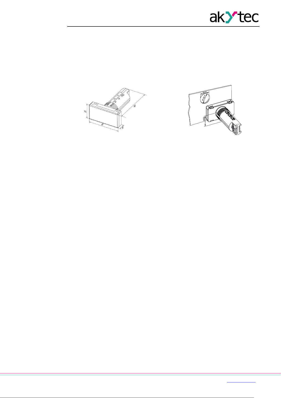
Appendix A. Dimensions
Fig. A1
Fig. A2
To prevent the device spinning, the borehole in the front panel must correspond to the
dimensions in Fig. A2.
 Loading...