

ITP14_2018.05_0279_EN
© All rights reserved
Subject to technical changes and misprints
ITP14
Universal process indicator
User guide
akYtec GmbH · Vahrenwalder Str. 269 A · 30179 Hannover · Germany · Tel.: +49 (0) 511 16 59 672-0 · www.akytec.de

1
Contents
1 Overview ........................................................................................................................................................ 2
2 Specifications ................................................................................................................................................ 2
2.1 Galvanic isolation ..................................................................................................................................... 2
2.2 Environmental conditions ....................................................................................................................... 2
3 Intended use .................................................................................................................................................. 3
4 Functions ....................................................................................................................................................... 3
5 Installation ..................................................................................................................................................... 3
5.1 Wiring ......................................................................................................................................................... 4
5.1.1 Input .................................................................................................................................................. 5
5.1.2 Output ............................................................................................................................................... 5
6 Operation ....................................................................................................................................................... 5
6.1 Control ....................................................................................................................................................... 5
6.2 Alarm .......................................................................................................................................................... 6
6.3 Filter ........................................................................................................................................................... 6
6.4 Square root function ................................................................................................................................ 7
6.5 Error ........................................................................................................................................................... 7
7 Programming ................................................................................................................................................. 7
8 Maintenance ................................................................................................................................................ 10
9 Transportation and storage ....................................................................................................................... 10
10 Scope of delivery ........................................................................................................................................ 10
Appendix A. Dimensions .................................................................................................................................. 10
akYtec GmbH · Vahrenwalder Str. 269 A · 30179 Hannover · Germany · Tel.: +49 (0) 511 16 59 672-0 · www.akytec.de
2
Power supply
24 (10…30) V DC
Power consumption, max.
1 W
Input
1
Input signal
0-5 mA, 0(4)-20 mA, 0(2)-10 V
Sampling time
0.3 s
Accuracy
± (0.2% FS + 1 digit)
Temperature influence
≤ 0.2% / 10 °C
Input resistance
0-5 mA, 0(4)-20 mA
≤ 120 ohm
0(2)-10 V
≥ 250 kohm
Output
1
Type
NPN transistor
Loading capacity
200 mA, 42 V DC
Enclosure
for panel mounting
Character height
14 mm
Dimensions
48 x 26 x 65 mm
Weight
approx. 30 g
0-5 mA
0-20 mA
0-10 V
2-10 V
1 Overview
ITP14 is a universally applicable process indicator and can be used with various current or
voltage standard signals. The device requires 24V DC auxiliary voltage. It is designed for
control and monitoring of industrial processes.
2 Specifications
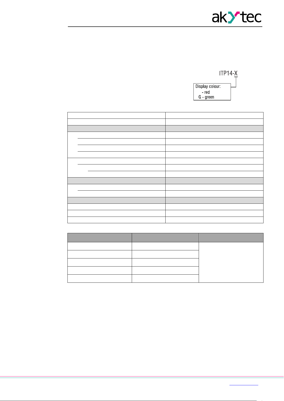
ITP14 can be ordered in two versions. They
differ in the display color. Ordering key:
Table 2.1 Technical data
Table 2.2 Linear signals
Display Input signal Measurement range, %
0- 5
0- 20
4- 20
4-20 mA
0…100
0- 10
2- 10
2.1 Galvanic isolation
The ITP14 has three potential groups:
− Power supply 24 V DC
− Analog input
− Digital output
Galvanic isolation from each group to enclosure 500 V
Galvanic isolation between groups 500 V
2.2 Environmental conditions
The device is designed for natural convection cooling. It should be taken into account when
choosing the installation site.
The following environment conditions must be observed:
− clean, dry and controlled environment, low dust level
akYtec GmbH · Vahrenwalder Str. 269 A · 30179 Hannover · Germany Tel.: +49 (0) 511 16 59 672-0 · www.akytec.de

3
Ambient temperature
-40…+60 °C
Storage temperature
-25…+55 °C
IP Code
front IP65, rear IP20
Protection class
III
Relative humidity
up to 80% (at +35°C, non-condensing)
Improper installation can cause seriou s or minor injuries and damage the device.
− closed non-hazardous areas, free of corrosive or flammable gases
Table 2.3
Conditions Permissible range
3 Intended use
The device may only be used in the manner described in this user guide, properly installed
and in accordance with the specification. Damages caused by disregarding the instructions
of this manual are without liability. Non-observance of the safety guidelines may result in
damage to the device and injury to personal.
Improper use
Any other use is considered improper. Especially to note:
− The ITP14 may not be used for medical devices that sustain, monitor or otherwise affect
human life or health.
− The device may not be used if the environmental conditions (temperature, humidity etc.)
are not within the limits indicated in the specification.
− The device may not be used in potentially explosive environment or in an atmosphere
with chemically active substances.
4 Functions
A 4-digit LED display with 14 mm character height is located on the front of the device to
display the process value or error messages in operation (see 6) and programming
parameters in programming mode (see 7). The function buttons are positioned on the rear
part of the device.
Main functions:
− Analog input 0-5 mA, 0(4)-20 mA, 0(2)-10 V
− Measuring and displaying of a process value
− Signal scaling
− Adjustable decimal point position
− Display range -999…9999
− ON/OFF control with NPN output
− Square root function (for special transmitters)
− Digital filter
− Alarm function
− Error indication when the input signal is out of range
− Error indication when wire break or short circuit
5 Installation
CAUTION
akYtec GmbH · Vahrenwalder Str. 269 A · 30179 Hannover · Germany Tel.: +49 (0) 511 16 59 672-0 · www.akytec.de
Installation must be performed only by fully qualified personnel.
The device is designed for panel mounting in a borehole of Ø22.5 mm (see Appendix A for
dimensional drawings).
Carefully position the supplied gasket on the display rear surface. Insert the cylindrical body
of the device into the borehole and tighten the nut from the rear side of the panel.

4
Switch on the power supply only after the wiring of the device has been completely
►
4.5 V to prevent the device damage. Disconnect the sensor in case of higher voltage.
►
Signal cables should be routed separately or screened from the supply cables.
Only a shielded cable may be used for signal li nes.
5...7
5.1 Wiring
CAUTION
NOTICE
NOTICE
performed
Switch off the device before checkin g th e sensor and connection lines.
For circuit integrity check use only the me asuring device with the output voltage max.
Fig. 5.1 Wire preparation
Do not use wire end ferrules to connect
stranded wires.
To connect fine-stranded wire, tin the wire
end.
Fig. 5.2 Connecting the wire to the terminal
To connect solid wire, push the wire into the
terminal.
To connect stranded wire, press the release
lever and push the wire into the terminal.
Fig. 5.3 Disconnecting the wire
Press the release lever to free the wire.
Fig. 5.4 Mounting
– The electrical connections are shown in Fig. 5.5-5.7, the terminal assignments in Table
5.1.
– Ensure that the device is provided with its own power supply line and electric fuse I = 0.5
A.
– Solid conductor cross-section: 0.2…0.8 mm². Stranded conductor cross-section:
0.45…0.7 mm². Wires should be stripped for approx. 8 mm.
akYtec GmbH · Vahrenwalder Str. 269 A · 30179 Hannover · Germany Tel.: +49 (0) 511 16 59 672-0 · www.akytec.de

5
Fig. 5.5 Current sensor wiring
Fig. 5.6 Voltage sensor wiring
Designation
Description
24VDC -
24VDC +
DO-
Output -
DO+
Output +
COM
Common -
U+
Voltage input +
I+
Current input +
►
As a precaution against inadvertent current reversal on output, a parallel diode (UVD
≥ 1.3U, I
≥ 1.3I) is usually included in the output circuit.
DO-
K
_
U
U
+
VD
DO+
5.1.1 Input
NOTICE
Table 5.1 Terminal assignment
Power supply
5.1.2 Output
The NPN transistor output is designed to control the low voltage relay up to 42 V DC / 200
mA
VD
Fig. 5.7 NPN transistor output
6 Operation
After the device is powered on the operating mode is activated. The type of the signal can be
selected in the parameter in.t “Input signal”. The complete list of the programming
parameters is shown in Table 7.2.
The input signal is digitalised, the square root calculated (if the function is enabled), the
signal scaled and displayed. The scale factor is calculated based on the parameter di.Lo
“Lower measuring limit” and di.Hi “Upper measuring limit”. The display decimal point can be
specified in the parameters di.P.
For other signal processing functions see sections 6.1…6.3. For displayed errors see Table
6.1.
6.1 Control
ON/OFF control is implemented with the NPN transistor output (see 5.1.2). The parameters
SP.Lo “Lower setpoint limit” and SP.Hi “Upper setpoint limit” specify the control limits. The
control function can be selected in the parameter Cnt:
− Heating
− Cooling
− Alarm within limits
− Alarm outside limits
akYtec GmbH · Vahrenwalder Str. 269 A · 30179 Hannover · Germany Tel.: +49 (0) 511 16 59 672-0 · www.akytec.de

6
The safe output state can be selected in the parameter out.E.
Fig. 6.1
Note:
Switching hysteresis: 0.05 x (SP.Hi – SP.Lo).
6.2 Alarm
If the control function Cnt is set and the alarm function d.FnC = ON, the display blinks with a
frequency of about 2 Hz when the output is switched on (see Fig. 6.1).
6.3 Filter
Undesirable signal fluctuations can be suppressed through the adjustable filter in the
parameter td “Filter time constant” (see Fig. 6.2 and Table 7.2).
The filter time constant can be set within the range 0…10 seconds. The higher the value, the
slower the display reaction to changes of the input signal and the lower the susceptibility to
interference is. The filter is deactivated if td = 0.
Fig. 6.2 Filter time constant
akYtec GmbH · Vahrenwalder Str. 269 A · 30179 Hannover · Germany Tel.: +49 (0) 511 16 59 672-0 · www.akytec.de

7
Possible cause
Signal
Threshold
Eг.1
Check the input signal.
GmbH.
LLLL
HHHH
|----|
Wire break or short
Key
Description
Press > 3 s:
– save the parameter
Increase value or menu
Decrease value or menu
6.4 Square root function
The function is intended for transmitters with the square characteristic. To enable the
function set the parameter Sqrt = ON.
6.5 Error
Table 6.1 Displayed errors
Display
Measured value error
Measured value is
below the lower limit for
the selected signal
Measured value is
above the upper limit for
the selected signal
- -
0-5 mA I < -0.2 mA
0-20 mA I < -0.2 mA
4-20 mA I < 3.8 mA
0-10 V U < -0.1 V
2-10 V U < 1.5 V
0-5 mA I > 5.5 mA
0-20 mA I > 22 mA
4-20 mA I > 22 mA
0-10 V U > 11 V
Remedy
Check the sensor and
connection lines.
Contact the Technical
Support of akYtec
Check the input signal
Check the input signal
circuit (only for 4-20 mA
and 2-10 V)
7 Programming
Table 7.1 Function buttons
+
2-10 V U > 11 V
4-20 mA I < 0.5 mA
Check the signal line
2-10 V U < 0.5 V
– enter the programming
mode
– exit the programming
mode
Press < 1 s:
Press > 3 s:
– enter the service menu
navigation
navigation
akYtec GmbH · Vahrenwalder Str. 269 A · 30179 Hannover · Germany Tel.: +49 (0) 511 16 59 672-0 · www.akytec.de
– Press and hold the button or to activate the ramp function while changing
parameter.

8
SP.Lo
SP.Hi
Cnt
oFF
OFF
Heat
Heating
CooL
Cooling
U
Alarm outside limits
П
Alarm within limits
in.t
td
out.E
ON
OFF
di.Lo
di.Hi
di.Hi
Upper measuring limit
-999...9999
affected by di.P
100
SQrt
ON
OFF
di.P
----
0000
---.-
000.0
--.--
00.00
-.---
0.000
d.FnС
ON
OFF
гES
0
User settings
1
Factory settings
CLbг
SoFt
Firmware version
-
– if no button was pressed within 20 s, the device returns to the operating mode
automatically.
Table 7.2 Programming parameters
Name Display Parameter Valid value Description Default
SP.Lo
SP.Hi
Cnt
in.t
td
out.E
di.Lo
SQrt
di.P
Lower setpoint limit -999...9999
Upper setpoint limit -999...9999
Control function
Input signal See Table 2.2 0-10 V
0BFilter time constant 0…10 s 0
Output safe state
Lower measuring limit -999...9999
Square root function
Decimal point
affected by di.P
affected by di.P
affected by di.P
0
30
U
OFF
0
OFF
---.-
d.FnС
Table 7.3 Service menu
Display Comments Valid values
Alarm function
Restore factory settings
Service function -
OFF
akYtec GmbH · Vahrenwalder Str. 269 A · 30179 Hannover · Germany Tel.: +49 (0) 511 16 59 672-0 · www.akytec.de

9
Fig. 7.1 Device menu
Note:
1. The minus sign is displayed in the most significant digit, together with 1. The display
range is -199.9...999.9 if di.P = ---.-,
2. When setting the signal limits, take into account that in some cases the correct value
cannot be displayed though there is no error indication.
Example 1:
di.Lo: -999 -> 4 mA di.Hi: 9999 -> 20 mA
For the input current of 3.8 mA the correct indication should be “-1068”. Actually “1068” will
be displayed.
Example 2:
di.Lo: -999 -> 4 mA di.Hi: 9999 -> 20 mA
For the input current of 20.8 mA the correct indication should be “10548”. Actually “0548” will
be displayed.
akYtec GmbH · Vahrenwalder Str. 269 A · 30179 Hannover · Germany Tel.: +49 (0) 511 16 59 672-0 · www.akytec.de

10
►
The device may have been damaged during transportati o n.
Report the transport damage immediately to the shipper and akYtec GmbH!
8 Maintenance
The maintenance includes:
– cleaning the housing and the terminals from dust, dirt and debris
– checking the fastening of the device
– checking the wiring (connecting leads, fastenings, mechanical damage)
The device should be cleaned with a damp cloth only. No abrasives or solvent-containing
cleaners may be used.
9 Transportation and storage
Pack the device in such a way as to protect it reliably against impact for storage and
transportation. The original packaging provides optimum protection.
If the device is not taken immediately after delivery into operation, it must be carefully stored
at a protected location. The device should not be stored in an atmosphere with chemically
active substances.
NOTICE
Permitted storage temperature: -25…+55 °C
Check the device for transport damage and completeness!
10 Scope of delivery
− ITP14 1
− Gasket 1
− Mounting nut 1
− User guide 1
Appendix A. Dimensions
Fig. A1 Fig. A2
To prevent the device spinning, the borehole in the front panel must correspond to the
dimensions in Fig. A.2.
akYtec GmbH · Vahrenwalder Str. 269 A · 30179 Hannover · Germany Tel.: +49 (0) 511 16 59 672-0 · www.akytec.de
 Loading...