

Page 1
ITP11(M04)_2018.05_0284_EN
© All rights reserved
Subject to technical changes and misprints
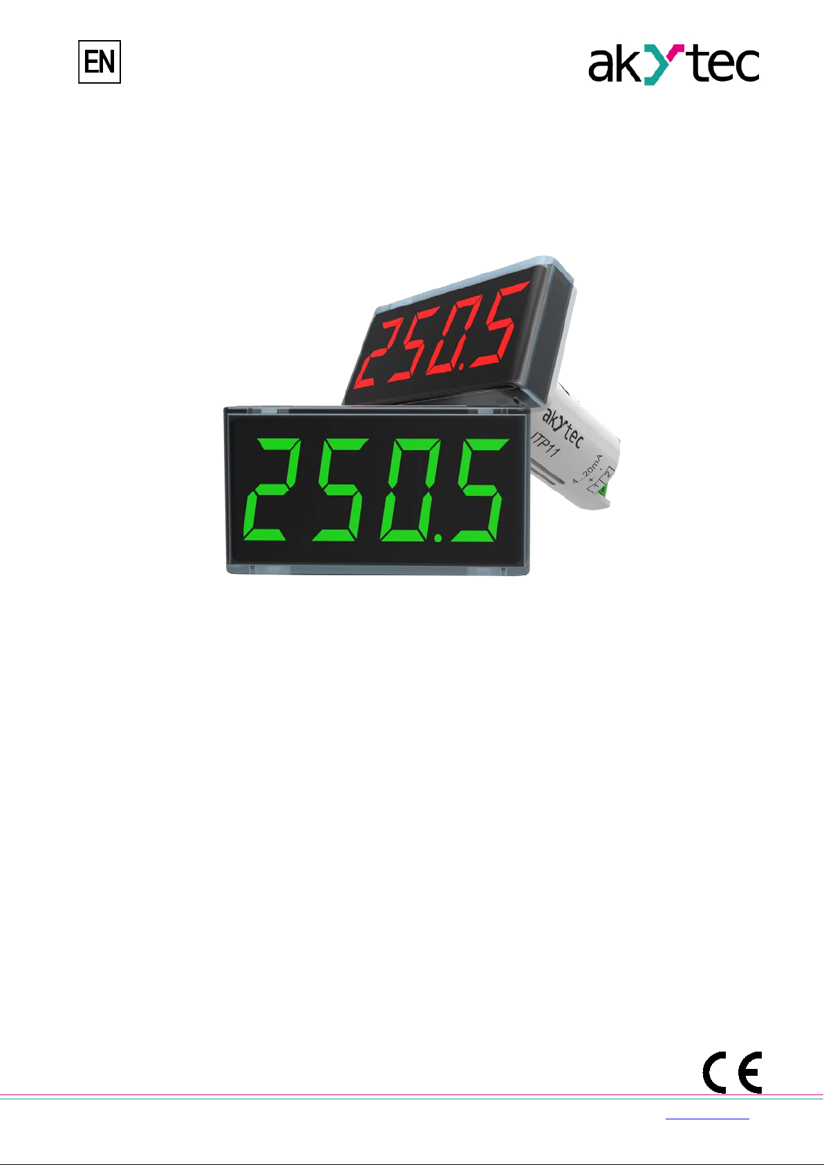
ITP11(M04)
Process indicator 4-20 mA
User guide
akYtec GmbH · Vahrenwalder Str. 269 A · 30179 Hannover · Germany · Tel.: +49 (0) 511 16 59 672-0 · www.akytec.de
Page 2

1
Contents
1 Overview ........................................................................................................................................................ 2
2 Specifications ................................................................................................................................................ 2
2.1 Environmental conditions ....................................................................................................................... 2
3 Intended use .................................................................................................................................................. 3
4 Functions ....................................................................................................................................................... 3
5 Installation ..................................................................................................................................................... 3
6 Operation ....................................................................................................................................................... 4
7 Programming ................................................................................................................................................. 6
8 Maintenance .................................................................................................................................................. 8
9 Transportation and storage ......................................................................................................................... 8
10 Scope of delivery .......................................................................................................................................... 9
Appendix A. Dimensions .................................................................................................................................... 9
akYtec GmbH · Vahrenwalder Str. 269 A · 30179 Hannover · Germany · Tel.: +49 (0) 511 16 59 672-0 · www.akytec.de
Page 3
2
Supply current
from current loop
Input signal
4-20 mA (2-wire)
Inputs
1
Measuring range
3.8…22.5 mA
Normal operation
3.2…25 mA
Voltage drop, max.
4 V
Accuracy
0.2% + 1 digit
Display
LED, 7-segment display
Character height
14 mm
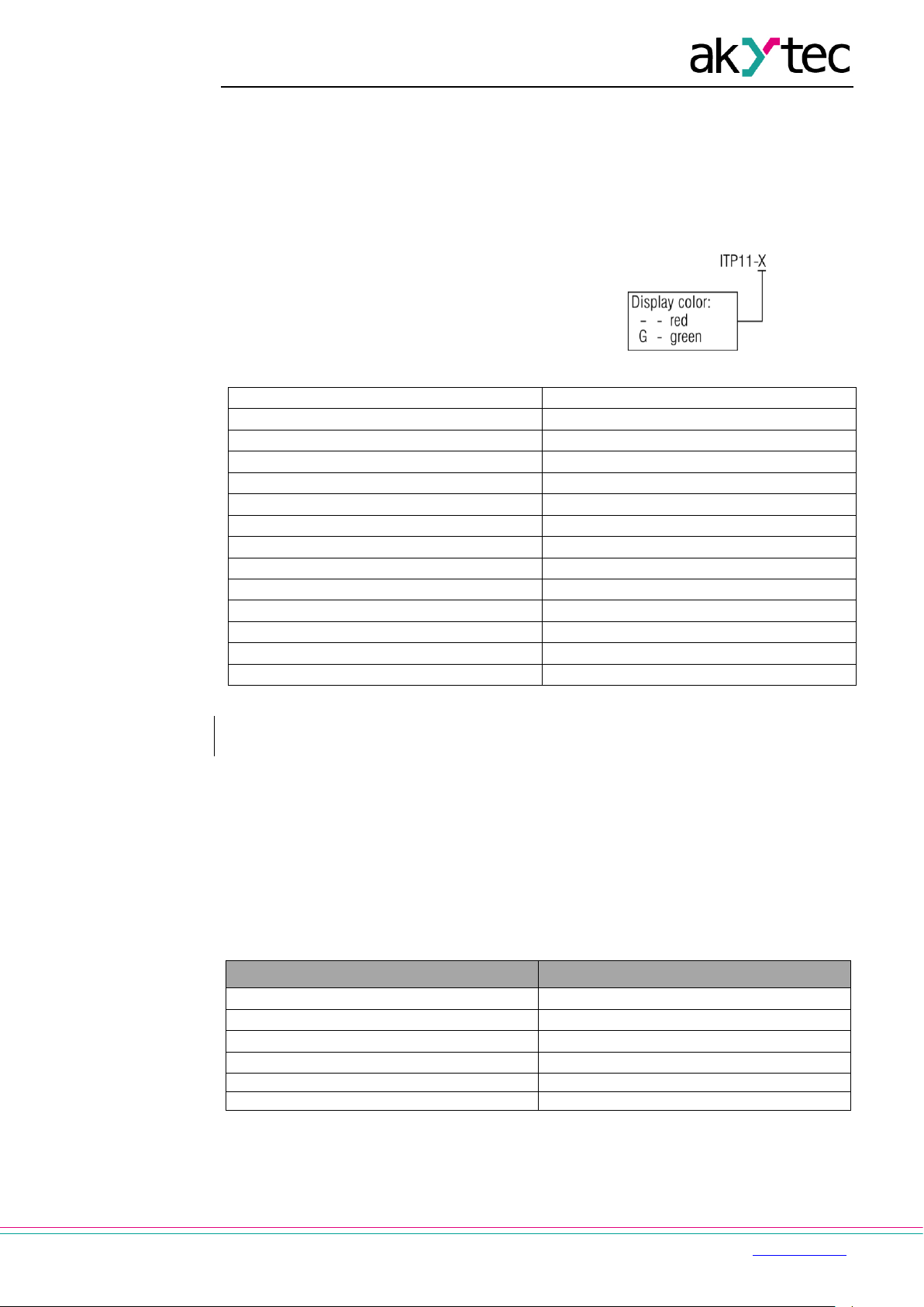
Display colour
red or green
Number of digits in display
4
Sampling time
1 s
Dimensions
48 x 26 x 65 mm
Weight
approx. 30 g
►
Before connecting the active output of ano ther device to the ITP11 input, ensure that
the output voltage is sufficient for correct operation of the ITP11 (> 4 V).
Ambient temperature
-40…+80 °C
Storage temperature
-25…+80 °C
IP Code
front IP65, rear IP20
Protection class
III
Relative humidity
up to 80% (non-condensing)
Altitude
up to 2000 m above sea level
1 Overview
The ITP11 is a universally applicable current loop process indicator. It can be connected to
any transmitter with 4-20 mA output. The device requires no auxiliary power and is supplied
directly from the current loop.
The device is designed for control and monitoring of industrial processes.
2 Specifications
ITP11 can be ordered in two versions. They
differ in the display color. Ordering key:
Table 2.1 Technical data
NOTICE
2.1 Environmental conditions
The device is designed for natural convection cooling. It should be taken into account when
choosing the installation site.
The following environment conditions must be observed:
− clean, dry and controlled environment, low dust level
− closed non-hazardous areas, free of corrosive or flammable gases
Table 2.2
Conditions Permissible range
akYtec GmbH · Vahrenwalder Str. 269 A · 30179 Hannover · Germany · Tel.: +49 (0) 511 16 59 672-0 · www.akytec.de
Page 4

3
3 Intended use
The device may only be used in the manner described in this user guide, properly installed
and in accordance with the specif icatio n. Dam ages caused by disregarding the instructions
of this manual are without liability.
Non-observance of the safety guidelines may result in damage to the device and injury to
personal.
Improper use
Any other use is considered improper. Especially to note:
– The ITP11 may not be used for medical devices that sustain, monitor or otherwise affect
human life or health.
– The device may not be used if the environmental conditions (temperature, humidity etc.)
are not within the limits indicated in the specification.
– The device may not be used in potentially explosive environment or in an atmosphere
with chemically active substances.
4 Functions
A 4-digit LED display with 14 mm character height is located on the front of the device to
display the process value or error messages in operation (see 6) and programming
parameters in programming mode (see 7). The function buttons are positioned on the rear
part of the device.
The device has the following functions:
− Measuring and displaying of the process value, received from a process control device
with 4-20 mA output
− Signal scaling
− Adjustable decimal point position
− Display range of -999…+9999
− Square root function (for special transmitters)
− Digital filter
− Alarm function
− Error indication when exceeding the measuring limits
− Access protection
Fig. 4.1 Block diagram
5 Installation
The device is designed for panel mounting in a borehole of Ø22.5 mm (see Appendix A for
dimensional drawings).
Carefully position the supplied gasket on the display rear surface. Insert the cylindrical body
of the device into the borehole and tighten the nut from the rear side of the panel.
Connect the device to the signal cable in accordance with Fig. 5.2-5.4.
The device factory settings can be changed before assembly if necessary. For this purpose
the display must be connected to a standard signal 4-20 mA.
akYtec GmbH · Vahrenwalder Str. 269 A · 30179 Hannover · Germany Tel.: +49 (0) 511 16 59 672-0 · www.akytec.de
Page 5

4
+
+
+
1
2
Device with
AO 4-20 mA
Power supply
ITP11
+
1
2
Device with
AO 4-20 mA
+
Power supply
ITP11
+
1
2
ITP11
...
...
+
Fig. 5.1 Mounting
Fig. 5.2 Connection to the device with
active output 4-20mA
Fig. 5.3 Connection to the device with
passive output 4-20mA
Fig. 5.4 Connection of 2 or more ITP11 to the one source of 4-20 mA
6 Operation
The operating mode is automatically activated if the standard signal 4-20 mA is connected to
the terminals.
The input signal is digitalised, the square root calculated (if the function is enabled), the
result scaled and displayed. The scale factor is calculated based on the parameter di.Lo
“Lower measuring limit” (for input signal 4 mA) and di.Hi “Upper measuring limit” (for input
signal 20 mA).
If the input signal is lower than 3.8 mA, the error message Lo is displayed.
akYtec GmbH · Vahrenwalder Str. 269 A · 30179 Hannover · Germany Tel.: +49 (0) 511 16 59 672-0 · www.akytec.de
If the input signal is higher than 22.5 mA, the error message Hi is displayed.
Page 6

5
Alarm outside
limits
t
t
t
Alarm within
limits
SP.Hi
SP.Lo
T
Filter
Undesirable signal fluctuations can be suppressed through the adjustable filter in the
parameter td “Filter time constant” (see Fig. 6.1, Table 7.1).
The filter time constant can be set within the range 0…10 seconds. The higher the value, the
slower the display reaction to changes of the input signal and the lower the susceptibility to
interference. The filter is deactivated if td = 0.
Fig. 6.1
Square root function
This function is intended for transmitters with the square characteristic. To enable the
function, the parameter Sqrt must be set to ON.
Alarm
The alarm function compares the input si gna l with the s etpoi nt lim its and makes the display
blink with frequency about 2 Hz, depending on the parameter d.FnC (see Fig. 6.2, Table 7.1)
Fig 6.2 Alarm function
akYtec GmbH · Vahrenwalder Str. 269 A · 30179 Hannover · Germany Tel.: +49 (0) 511 16 59 672-0 · www.akytec.de
Page 7

6
PS
ON
OFF
di.P
----
0000
---.-
000.0
--.—
00.00
-.---
0.000
di.Lo
Lower measuring
di.Hi
Upper measuring
td
Filter time
SQrt
Square root
ON
OFF
d.FnC
oFF
OFF
Alarm outside
Alarm within
SP.Lo
Lower setpoint
SP.Hi
Upper setpoint
7 Programming
Use the button to enter the programming mode or to apply the changes.
Use the buttons and to select or change the parameter. Press and hold the button to
activate the ramp function while changing parameter.
To return to the operating mode, the button must be pressed for longer than 5 s.
If no button is pressed within 20 s, the device reverts to operating mode automatically.
The parameter list is presented in Table 7.1 and the flowchart in Fig. 7.1.
Table 7.1
Name Display Parameter Valid value Description Default
PS
di.P
di.Lo
di.Hi
td
SQrt
d.FnC
SP.Lo
SP.Hi
Access protection
Decimal point
limit
limit
constant
function
Alarm function
limit
limit
-999...9999
-999...9999
U
П
-999...9999
-999...9999
OFF
--.--
affected by di.P
affected by di.P
0…10 s 0
limits
limits
affected by di.P
affected by di.P
4.00
20.00
OFF
OFF
4.00
20.00
akYtec GmbH · Vahrenwalder Str. 269 A · 30179 Hannover · Germany Tel.: +49 (0) 511 16 59 672-0 · www.akytec.de
Page 8

7
Fig 7.1
Notes:
1 The minus sign is displayed in the most significant digit, together with 1. If di.P = ---.-, the
display range is -99.9...999.9.
2 When setting the signal limits, take into account that in some cases the correct value
cannot be displayed though there is no error indication.
Example 1:
di.Lo: -999 -> 4 mA
di.Hi: 9999 -> 20 mA
For the input current of 3.9 mA the correct indication should be “-1075”.
akYtec GmbH · Vahrenwalder Str. 269 A · 30179 Hannover · Germany Tel.: +49 (0) 511 16 59 672-0 · www.akytec.de
Page 9

8
Lo
Input current lower than 3.8 mA
Check input signal
Hi
Input current higher than 22.5 mA
Check input signal
I- - - -
The top of the parameter list is reached
- - - - I
The bottom of the parameter list is
No input signal
Check input signal
Reverse polarity
Check polarity
►
The device may have been damaged during transportati o n.
Report the transport damage immediately to the shipper and akYtec GmbH!
Example 2:
di.Lo: -999 -> 4 mA
di.Hi: 9999 -> 20 mA
For the input current of 20.8 mA the correct indication should be “10548”. Actually “0548”
will be displayed.
If the access protection is disabled (PS = oFF), the passcode will be not requested.
If the access protection is activated, 0 is displayed.
Use the buttons and to enter the passcode 5, then press the button to confirm.
If an incorrect passcode is entered, the device returns to the operating mode.
Potential errors and remedies are listed in Table 7.2.
Table 7.2 Error messages
Display Possible cause Remedy
reached
empty display
8 Maintenance
The maintenance includes:
– cleaning the housing and the terminals from dust, dirt and debris
– checking the fastening of the device
– checking the wiring (connecting leads, fastenings, mechanical damage)
The device should be cleaned with a damp cloth only. No abrasives or solvent-containing
cleaners may be used.
9 Transportation and storage
Pack the device in such a way as to protect it reliably against impact for storage and
transportation. The original packaging provides optimum protection.
If the device is not taken immediately after delivery into operation, it must be carefully stored
at a protected location. The device should not be stored in an atmosphere with chemically
active substances.
Permitted storage temperature: -25…+80 °C
NOTICE
akYtec GmbH · Vahrenwalder Str. 269 A · 30179 Hannover · Germany Tel.: +49 (0) 511 16 59 672-0 · www.akytec.de
Check the device for transport damage and completeness!
Page 10

9
Ø 22,5
20,8
М22
10 Scope of de livery
− ITP11 1
− Gasket 1
− Mounting nut 1
− User guide 1
Appendix A. Dimensions
Fig. A1 Fig. A2
To prevent the device spinning, the borehole in the front panel must correspond to the
dimensions in Fig. A.2.
akYtec GmbH · Vahrenwalder Str. 269 A · 30179 Hannover · Germany Tel.: +49 (0) 511 16 59 672-0 · www.akytec.de
 Loading...