

Page 1

akYtec GmbH · Vahrenwalder Str. 269 A · 30179 Hannover · Germany · Tel.: +49 (0) 511 16 59 672-0 · www.akytec.de
akYtec ALP
Programming software for akYtec programmable devices
User manual
ALP_2020.07_V17_EN
© All rights reserved
Subject to technical changes and misprints
Page 2

akYtec GmbH · Vahrenwalder Str. 269 A · 30179 Hannover · Germany · Tel.: +49 (0) 511 16 59 672-0 · www.akytec.de
1
Contents
1 General ............................................................................................................................................................ 4
1.1 Abbreviations and terms ........................................................................................................................... 4
1.2 About software .......................................................................................................................................... 4
1.3 System requirements ................................................................................................................................ 4
2 User interface .................................................................................................................................................. 6
2.1 Menu ......................................................................................................................................................... 6
2.2 Toolbars .................................................................................................................................................... 9
2.3 Workspace .............................................................................................................................................. 10
2.4 Library Box .............................................................................................................................................. 11
2.5 Property Box ............................................................................................................................................ 12
2.6 Display Manager ..................................................................................................................................... 12
2.7 Status bar ................................................................................................................................................ 14
2.8 Variable Box ............................................................................................................................................ 15
2.9 Component Manager .............................................................................................................................. 15
2.9.1 Online Database .............................................................................................................................. 16
2.9.2 Local library ...................................................................................................................................... 17
3 Usage basics ................................................................................................................................................. 18
3.1 Program execution .................................................................................................................................. 18
3.2 Program cycle time.................................................................................................................................. 18
3.3 Project creation ....................................................................................................................................... 18
3.4 Connection to device ............................................................................................................................... 19
3.4.1 OFFLINE mode ................................................................................................................................ 20
3.5 Device information................................................................................................................................... 20
3.6 Project information .................................................................................................................................. 21
3.7 Upload project to device .......................................................................................................................... 21
3.8 Firmware update / repair ......................................................................................................................... 22
3.8.1 Forced firmware update / repair ....................................................................................................... 23
4 Device configuration .................................................................................................................................... 24
4.1 Display ..................................................................................................................................................... 24
4.2 Clock ....................................................................................................................................................... 24
4.3 Interfaces ................................................................................................................................................. 25
4.3.1 Modbus working ............................................................................................................................... 25
4.3.2 Add / remove interface ..................................................................................................................... 27
4.3.3 RS485 Interface configuration ......................................................................................................... 28
4.4 Extension modules .................................................................................................................................. 33
4.5 Inputs ....................................................................................................................................................... 33
4.6 Outputs .................................................................................................................................................... 34
Page 3

akYtec GmbH · Vahrenwalder Str. 269 A · 30179 Hannover · Germany · Tel.: +49 (0) 511 16 59 672-0 · www.akytec.de
2
4.7 Calibration ............................................................................................................................................... 35
4.7.1 Input calibration ................................................................................................................................ 35
4.7.2 Output calibration ............................................................................................................................. 35
4.8 Change target device .............................................................................................................................. 36
5 Variables ........................................................................................................................................................ 37
5.1 Properties ................................................................................................................................................ 37
5.2 Data type ................................................................................................................................................. 38
5.3 Standard variables .................................................................................................................................. 38
5.4 Service variables ..................................................................................................................................... 39
5.5 Network variables .................................................................................................................................... 39
5.6 Copy / paste variable block ..................................................................................................................... 40
6 Library ........................................................................................................................................................... 42
6.1 Functions ................................................................................................................................................. 42
6.1.1 Logical operators ............................................................................................................................. 42
6.1.2 Mathematical operators ................................................................................................................... 44
6.1.3 Relational operators ......................................................................................................................... 47
6.1.4 Bitshift operators .............................................................................................................................. 49
6.1.5 Bit operators ..................................................................................................................................... 50
6.2 Function blocks ....................................................................................................................................... 52
6.2.1 Triggers ............................................................................................................................................ 52
6.2.2 Timers .............................................................................................................................................. 54
6.2.3 Generators ....................................................................................................................................... 57
6.2.4 Counters........................................................................................................................................... 57
6.2.5 Analog .............................................................................................................................................. 60
6.3 Project macros ........................................................................................................................................ 62
6.3.1 Export, import, download macro ...................................................................................................... 63
6.3.2 FB in macro ...................................................................................................................................... 63
6.3.3 New macro using main menu .......................................................................................................... 64
6.3.4 New macro using context menu ...................................................................................................... 65
6.3.5 Update macro .................................................................................................................................. 66
6.3.6 Replace macro ................................................................................................................................. 66
6.3.7 Changing I/O points order ................................................................................................................ 67
6.4 Display elements ..................................................................................................................................... 67
6.4.1 Text box ........................................................................................................................................... 68
6.4.2 I/O box (INT/REAL) .......................................................................................................................... 68
6.4.3 I/O box (BOOL) ................................................................................................................................ 70
6.4.4 Dynamic box .................................................................................................................................... 70
6.4.5 ComboBox ....................................................................................................................................... 71
7 Circuit program development ..................................................................................................................... 73
7.1 Using of library blocks ............................................................................................................................. 73
Page 4

akYtec GmbH · Vahrenwalder Str. 269 A · 30179 Hannover · Germany · Tel.: +49 (0) 511 16 59 672-0 · www.akytec.de
3
7.2 Using of text field ..................................................................................................................................... 74
7.3 Using of variables .................................................................................................................................... 75
7.4 Using of constants ................................................................................................................................... 76
7.5 Using of delay lines ................................................................................................................................. 76
7.6 Network data exchange .......................................................................................................................... 77
7.7 Read / write in FB .................................................................................................................................... 78
7.8 Conversion blocks ................................................................................................................................... 79
7.9 Arrange elements .................................................................................................................................... 79
7.10 Execution sequence ............................................................................................................................ 80
7.11 Simulation ............................................................................................................................................ 80
7.11.1 Operation ......................................................................................................................................... 80
7.11.2 Watch Window ................................................................................................................................. 82
7.12 Online debugging................................................................................................................................. 82
8 Display programming .................................................................................................................................. 84
8.1 Display Editor .......................................................................................................................................... 85
8.2 Graphical structure .................................................................................................................................. 85
8.3 Form properties / Jumps ......................................................................................................................... 85
8.4 Copy / paste display form ........................................................................................................................ 87
9 Keyboard shortcuts...................................................................................................................................... 88
10 Program examples ....................................................................................................................................... 89
10.1 Task 1: Light switch with automatic switch-off ..................................................................................... 89
10.2 Task 2: Mixer control ........................................................................................................................... 91
Page 5

General
akYtec GmbH · Vahrenwalder Str. 269 A · 30179 Hannover · Germany · Tel.: +49 (0) 511 16 59 672-0 · www.akytec.de
4
1 General
1.1 Abbreviations and terms
Abbreviations and terms used in this manual:
Table 1.1
Abbreviations
and terms
Explanation
ALP
Programming software
FBD
Function Block Diagram is a graphical programming language
Function
Structural unit of a program with one return value. The function does
not store information about its internal state, i.e. if the function is
called with the same input values, it will return the same output
value.
Function block
Structural unit of a program with internal memory and one or more
output values. It is used in a program as an instance, i.e. a copy with
its own memory.
Macro
Function block created by the user
Program cycle
Execution time of the circuit program, which depends on its complexity
Project
User application created for a programmable device with ALP software
Target device
Device for which the project is created
Workspace
Area in the software user interface to create a user program by placing program blocks and connecting lines between them
1.2 About software
ALP is the programming software for programmable devices of akYtec GmbH. The programming language is the graphical language FBD (Function block diagram). The software enables testing of the created program and its upload to the non-volatile memory of
a programmable device.
Each project contains one or several circuit programs and a device configuration.
The first workspace contains the main circuit program. Macros (user function blocks) can
be created as circuit programs on separate workspaces.
If the target device has a display, it can be programmed using display forms, each of
them is opened in separate workspace.
Only one project at a time can be opened.
1.3 System requirements
ALP software runs on Windows XP/Vista/7/8/10. Pre-installed software .NET Framework
4.0 is required. If not installed, you will be asked to install it.
Minimum hardware requirements:
1.5 GHz processor
1 GB RAM
100 MB available hard disk space
Free USB port
Page 6

General
akYtec GmbH · Vahrenwalder Str. 269 A · 30179 Hannover · Germany · Tel.: +49 (0) 511 16 59 672-0 · www.akytec.de
5
Keyboard and mouse
Screen resolution 1024x768
Recommended hardware requirements:
3.2 GHz processor
4 GB RAM
200 MB available hard disk space
Free USB port
Keyboard and mouse
Screen resolution 1280x800
Internet connection is required for:
Software update
Device firmware update
Slave device template download
Macros download in Component Manager
Page 7
User interface
akYtec GmbH · Vahrenwalder Str. 269 A · 30179 Hannover · Germany · Tel.: +49 (0) 511 16 59 672-0 · www.akytec.de
6
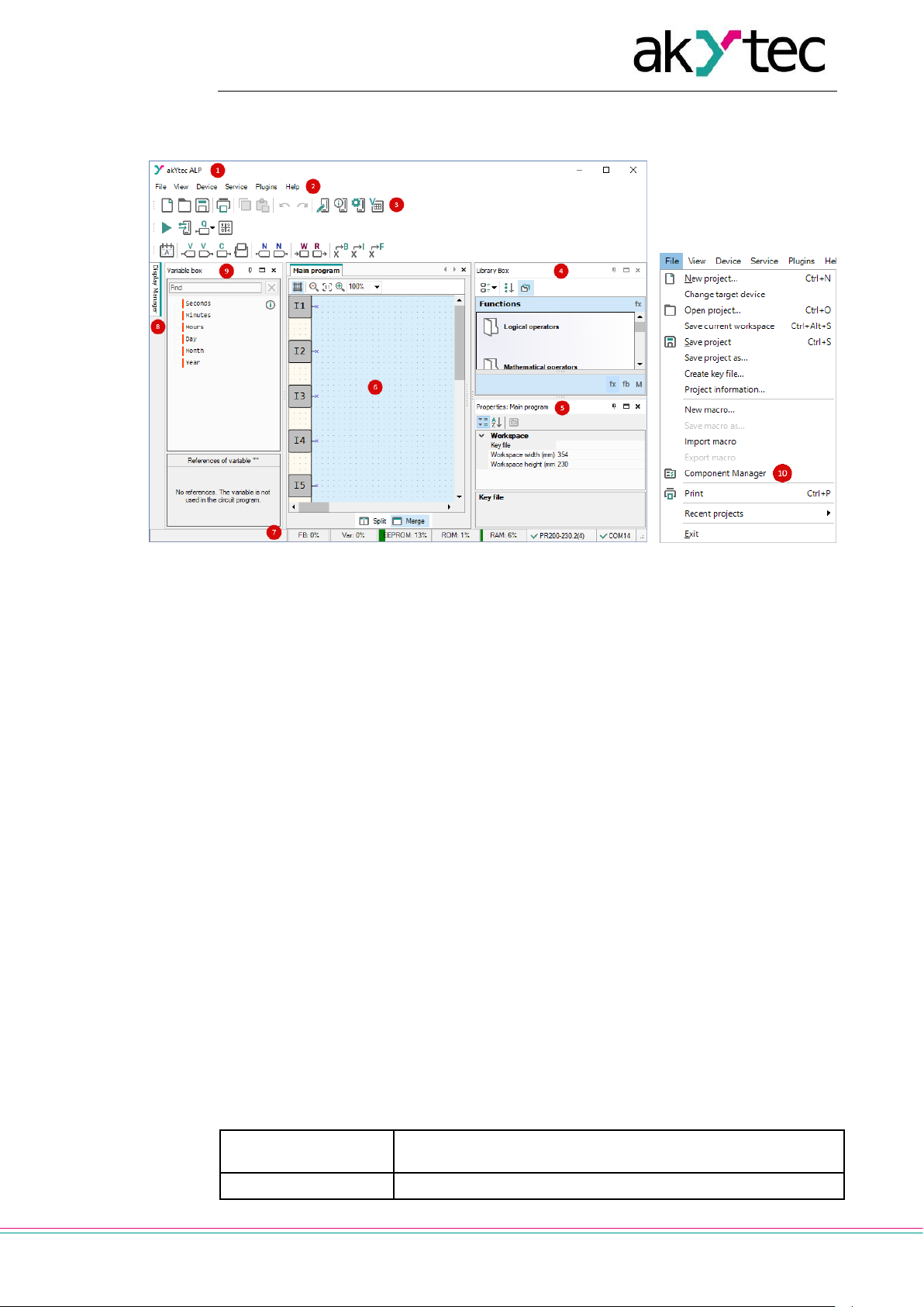
2 User interface
Fig. 2.1
1. Title bar – shows the name of the software and the path to the open project file
2. Menu bar – consists of the following groups: File, View, Device, Service, Plugins and
Help
3. Toolbars – Standard, Service and Insert: quick access to the essential functions of
ALP
4. Library Box – a panel that displays all the functions, function blocks, and macros
that can be added to the project
5. Property Box – a panel where the properties of the selected project element can be
viewed and modified
6. Workspace – a field in the user interface where a circuit program, display structure
or a display form can be viewed and modified
7. Status bar – shows status and error messages, target device memory usage, status
of the connected device and the programming interface
8. Display Manager – a tool to program the displayed information (available only for devices with display)
9. Variable Box – a panel in which all project variables with their parameters and references are displayed. Use drag-and-drop to place a variable block in a circuit program.
10. Component Manager – a special tool in a separate window to access the Online Database and to add the elements from Online Database to an offline library or to the
project library. Internet connection is needed.
2.1 Menu
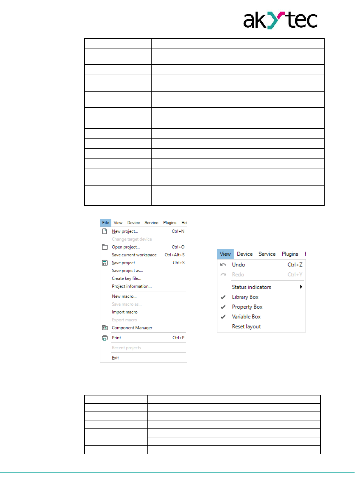
Table 2.1 Menu File
New project
Open a new project. The current project will be closed. (sect.
3.3)
Change target device
Change the target device in the project (sect. 4.8)
Page 8
User interface
akYtec GmbH · Vahrenwalder Str. 269 A · 30179 Hannover · Germany · Tel.: +49 (0) 511 16 59 672-0 · www.akytec.de
7
Open project
Open a previously saved project
Save current workspace
Save the currently opened workspace
Save project
Save the current project
Save project as…
Make a copy of the project in a different folder or with a different name
Create key file…
Create a file with a key to protect the project from unauthorized
access (in development)
Project information…
View and modify the information about the project (sect. 3.6)
New macro…
Open the new macro in the separate workspace (sect. 6.3.1)
Save macro as…
Save the current macro under a new name in the project library
Import macro
Import a macro from a file into the project library (sect. 6.3.3)
Export macro
Save the current macro as a file (sect. 6.3.2)
Component Manager
Open the Component Manager interface (sect. 2.9)
Print
Open the dialog to set the print options and print the active
workspace
Recent projects
List of recently opened projects
Exit
Close ALP
Fig. 2.2 Menu File
Fig. 2.3 Menu View
Table 2.2 Menu View
Undo
Undo the last action
Redo
Redo the last undone action
Status indicators
Add / remove the indicators to / from the status bar (sect. 2.7)
Library Box
Show / hide Library Box (sect. 2.4)
Property Box
Show / hide Property Box (sect. 2.5)
Variable Box
Show / hide Variable Box (sect. 2.8)
Display Manager *
Show / hide Display Manager (sect. 2.6)
* Available only for devices with display
Page 9
User interface
akYtec GmbH · Vahrenwalder Str. 269 A · 30179 Hannover · Germany · Tel.: +49 (0) 511 16 59 672-0 · www.akytec.de
8
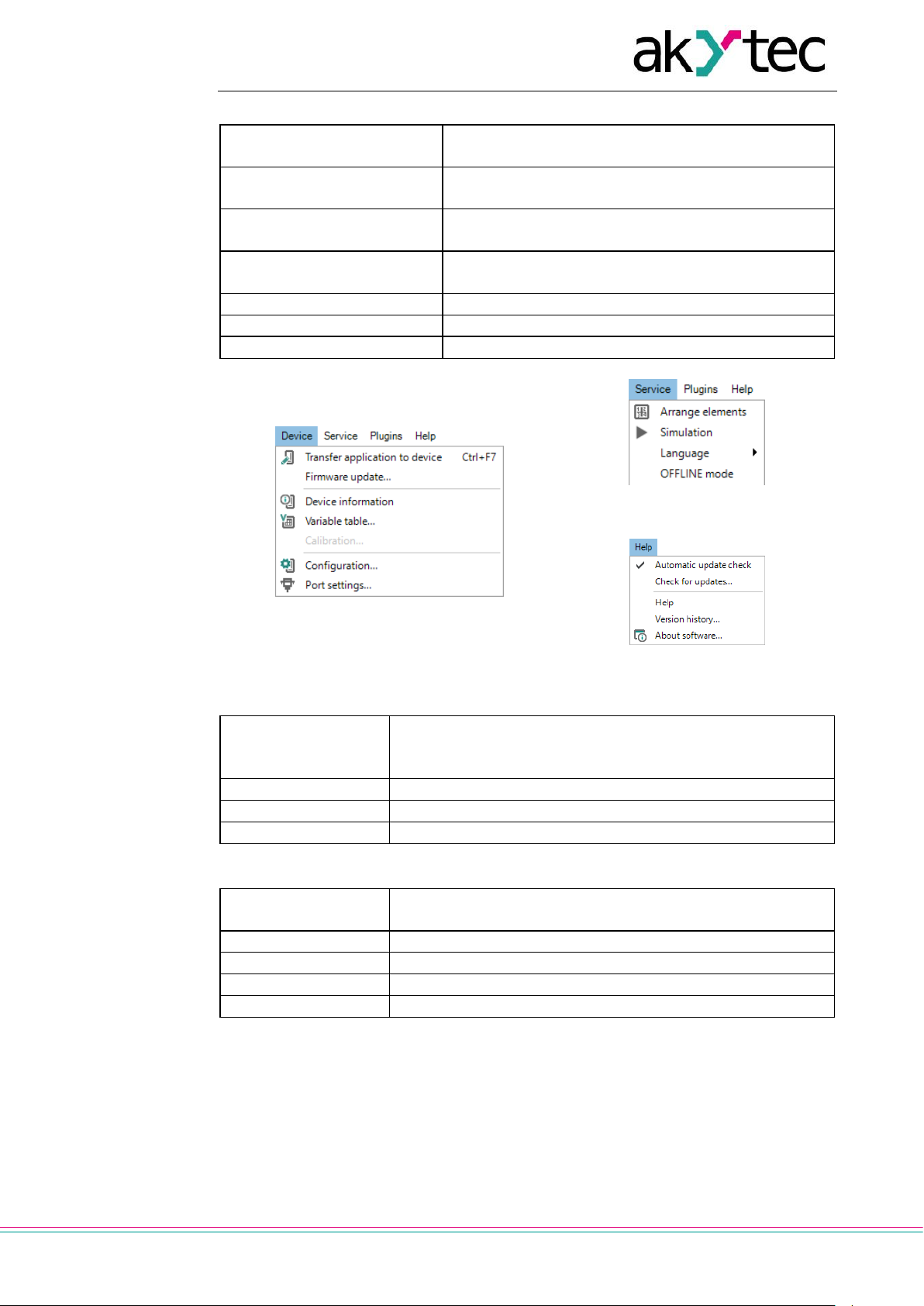
Table 2.3 Menu Device
Transfer application to device
Upload the current project to the device memory (sect.
3.7)
Firmware update…
Update the firmware of the connected device (sect.
3.8)
Device information
Information about the software, the target device and
the connected device (sect. 3.5)
Variable table…
The editable table of the project variables with their
parameters (sect. 5)
Calibration…
Start calibration (sect. 4.7)
Configuration…
Device configuration (sect. 4)
Port settings…
Settings of the programming interface (sect. 3.4)
Fig. 2.4 Menu Device
Fig. 2.5 Menu Service
Fig. 2.6 Menu Help
Table 2.4 Menu Service
Arrange elements
Function blocks of the same type are automatically renumbered in the workspace from top to bottom and from right to
left (sect. 7.9)
Simulation
Start / stop simulation (sect. 7.11)
Language
Select the interface language
OFFLINE mode
Activate OFFLINE mode (sect. 3.4.1)
Table 2.5 Menu Help
Automatic update
check
If activated, the update check is performed on program startup
Check for updates
Check if software updates are available
Help
Online help
Version history
The list of changes for all software versions
About Software
Information about the current software version
Page 10
User interface
akYtec GmbH · Vahrenwalder Str. 269 A · 30179 Hannover · Germany · Tel.: +49 (0) 511 16 59 672-0 · www.akytec.de
9
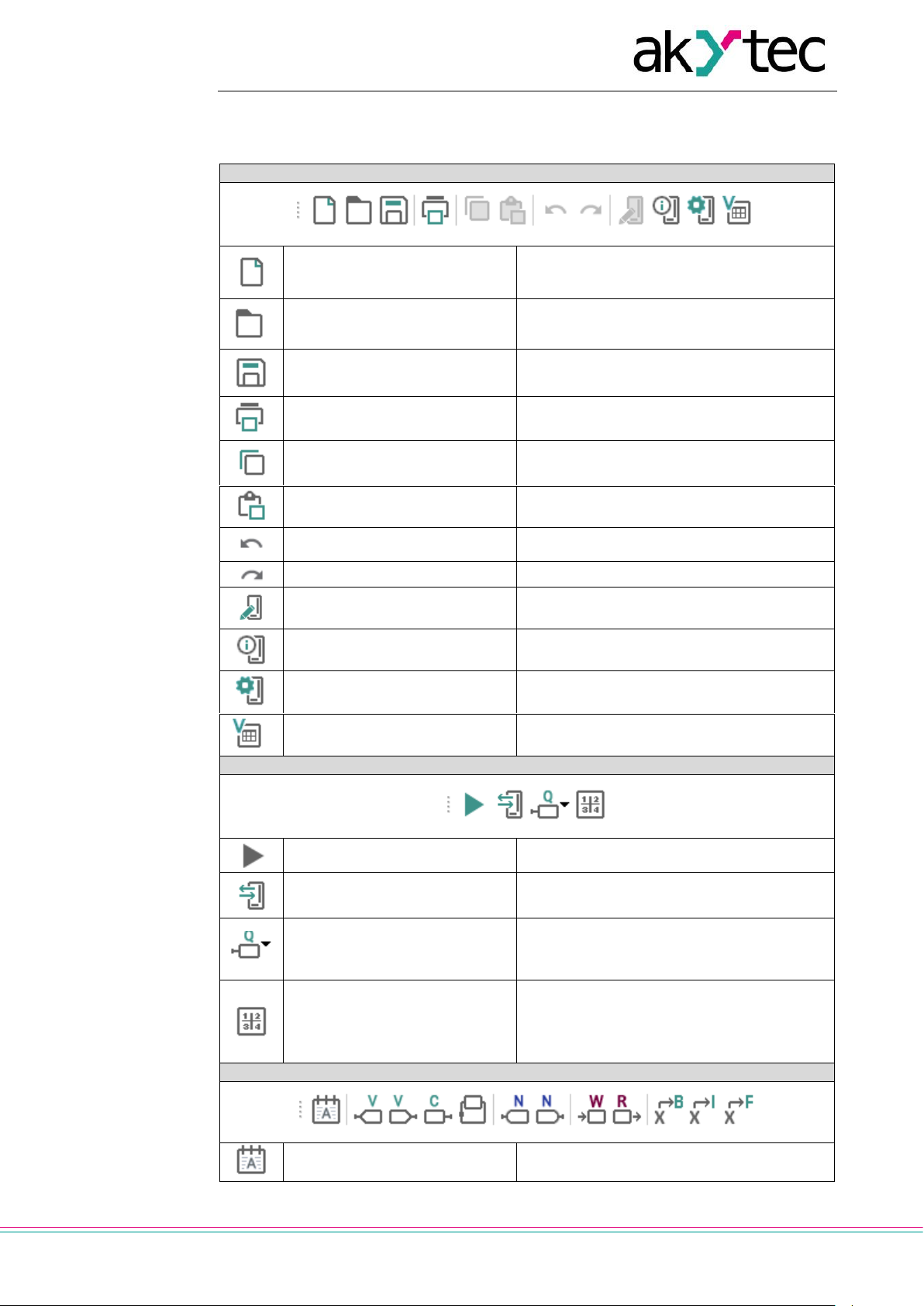
2.2 Toolbars
Table 2.6
Standard
New project
Open a new project. The current project will
be closed.
Open project
Open a previously saved project
Save project
Save the current project
Print
Open the dialog to set the print options for
the current workspace
Copy
Copy the element selected in the workspace
Paste
Paste the copied element
Undo
Undo the last action
Redo
Redo the last undone action
Transfer application to device
Upload the current project to the device
memory
Device information
Information about the software, the target
device and the connected device (sect. 3.5)
Configuration…
Device configuration (sect. 4)
Variable table…
Open the table of project variables for editing (sect. 5)
Service
Simulation
Start / stop simulation (sect. 7.11)
Online debugging
Start / stop online debugging (sect. 7.12)
Execution order
Change the execution order for the outputs
or delay lines in a circuit program or in a
macro (sect. 7.10)
Arrange elements
Function blocks of the same type are automatically renumbered in the workspace
from top to bottom and from right to left
(sect. 7.9)
Insert
Comment field
Text field for program comments (sect. 7.2)
Page 11

User interface
akYtec GmbH · Vahrenwalder Str. 269 A · 30179 Hannover · Germany · Tel.: +49 (0) 511 16 59 672-0 · www.akytec.de
10
Variable output block
Variable, which value can be written in the
program (sect. 7.3)
Variable input block
Variable, which value can be read in the
program (sect. 7.3)
Constant block
Constant value (sect. 7.4)
Delay line
Feedback with one-cycle delay (sect. 7.5)
Network variable output block
Variable, which value can be written via
network (sect. 7.6)
Network variable input block
Variable, which value can be read via network (sect. 7.6)
Block WriteToFB
Connects the input value of the block to the
selected parameter of the selected function
block and used to change the parameter
(sect. 7.7)
Block ReadFromFB
Connects the output value of the block to
the selected parameter of the selected
function block and used to read the parameter (sect. 7.7)
Conversion to BOOL
Conversion of any value to a BOOL value
(sect. 7.8)
Conversion to INT
Conversion of any value to an INT value
(sect. 7.8)
Conversion to REAL
Conversion of any value to a REAL value
(sect. 7.8)
2.3 Workspace
When a project is opened, the workspace with the tab Main program is shown in the
middle part of the window (Fig. 2.7).
Fig. 2.7 Workspace
Circuit program is built and modified by placing program blocks and connecting lines between them in the workspace. The size of the workspace can be changed in Property
Box. The inputs (left) and outputs (right) are signed as follows:
Ix – digital inputs
AIx – analog inputs
Qx – relay outputs
AOx – analog outputs
Page 12
User interface
akYtec GmbH · Vahrenwalder Str. 269 A · 30179 Hannover · Germany · Tel.: +49 (0) 511 16 59 672-0 · www.akytec.de
11
Fx – LED indicators
The numbers (x) correspond to the ordinal numbers of physical I/O points of the target
device. I/O points can be moved up and down along the workspace by drag-and-drop.
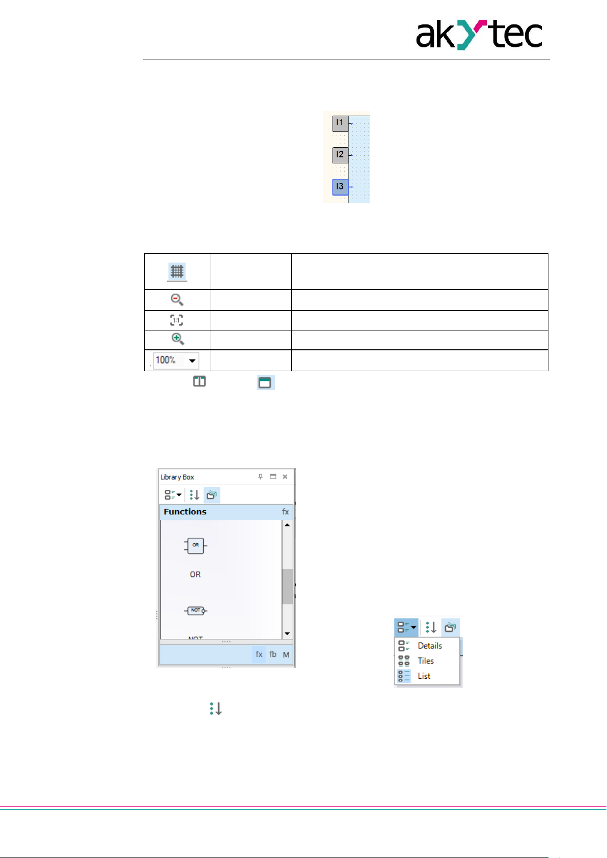
Fig. 2.8
Table 2.7 Workspace toolbar
Show / hide
grid
Show / hide vertical and horizontal rulers and a grid in
the workspace. If the grid is visible, the blocks and
connecting lines are snapped to the grid.
Zoom -
Decrease the workspace by 10%
Original size
Return to the original size (100%)
Zoom +
Increase the workspace by 10%
Select scale
Scale list from 20% to 400%
The icons Split and Merge are located on a toolbar below the workspace. Use
the icon Split to show the same circuit program in two workspaces. It can be useful if the
program is too large and you want to view two different parts of the program at the same
time. Use the icon Merge to return to one workspace.
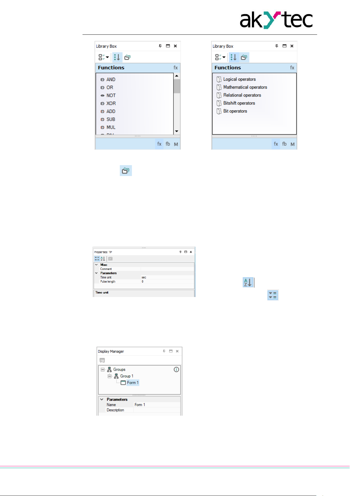
2.4 Library Box
The panel Library Box is a summary of program
blocks available in the project. The panel consists
of three libraries: Functions, Function blocks
and Project macros.
Select an item on the lower toolbar of the panel to
show the respective content.
The standard position of the panel is the upper
right window corner (can be changed).
The panel view can be changed using the icons on
the upper toolbar.
Fig. 2.9 Grouped tiles
Click the icon Show all to show all the blocks of the selected library (Fig. 2.10):
Page 13
User interface
akYtec GmbH · Vahrenwalder Str. 269 A · 30179 Hannover · Germany · Tel.: +49 (0) 511 16 59 672-0 · www.akytec.de
12
Fig. 2.10 Show all
Fig. 2.11 Show grouped
Click the icon Show grouped to show the blocks of the selected library grouped
(Fig. 2.11). Double-click the folder to open it.
For descriptions of the library groups and individual blocks see sect. 6.
2.5 Property Box
The panel Property Box is used to view and modify the parameters of the program elements. Select the element to view its properties.
Fig. 2.12
The standard position of the panel is the
lower right window corner (can be
changed).
The parameters are shown grouped by
categories by default.
To show them in alphabetical order,
click the icon . To show them
grouped, click the icon .
Select the parameter input field to edit
its value.
2.6 Display Manager
Fig. 2.13
If the target device has a display, the displayed information can be programmed using one or more display forms. For further
details about display programming see
sect. 8.
The programming is carried out using the
programming tool Display Manager. The
tab Display Manager is located in the upper
left corner of the window. Click the tab to
open the panel. The panel contains a
toolbar, a display form hierarchical structure
(tree) and a list of properties of the selected
object.
Page 14

User interface
akYtec GmbH · Vahrenwalder Str. 269 A · 30179 Hannover · Germany · Tel.: +49 (0) 511 16 59 672-0 · www.akytec.de
13
Fig. 2.14
Fig. 2.15
The parameters of the selected display
form are shown in the lower part of the
panel.
To program the selected form, open it in a
separate workspace Display Editor (Fig.
2.16), using the context menu or doubleclick the form in the group (Fig. 2.15).
The workspace shows the selected display
form with the icons on the right of it,
which are used to change the number of
the displayed rows. The rows displayed first
are bold outlined.
For working with Display Editor see sect.
8.1.
If more than one display forms are created,
you should specify “jumps” between them
so that the operator can switch between
forms to see the desired information. It can
be done in a separate workspace Structure
Editor (Fig. 2.17), presented the graphical
structure of display forms with “jumps” and
their conditions. To open it, use the command Edit group in the group context
menu (Fig. 2.14).
For working with Structure Editor see sect.
8.2.
Fig. 2.16 Display Editor
Page 15

User interface
akYtec GmbH · Vahrenwalder Str. 269 A · 30179 Hannover · Germany · Tel.: +49 (0) 511 16 59 672-0 · www.akytec.de
14
Fig. 2.17 Structure Editor
Table 2.8 Editor toolbars
Common
Save workspace
Zoom
Zoom out by 10%
Original size
Zoom in by 10%
Select scale
Display form
Add display form
Delete display form
2.7 Status bar
Status and error messages are displayed in the left field of the status bar.
Besides that the status bar contains different status indicators that show information
about the memory usage of the target device (resource indicators), status of the connected device and the programming interface. Which indicators are available in the status
bar, depends on the type of the target device.
Fig. 2.18
Resource indicators show the used resource in percent of the total available amount.
Move the mouse over the indicator to see the absolute amount of the resource.
If the device is connected, the status bar contains the following information:
FB – the number of the available and used function blocks
Var – the number of the available and used variables
Note: Some variables can be created by the software automatically, if such elements as delay lines or multiple connecting lines with common nodes are used in
a project.
Stack – the number of the available and used stack levels
EEPROM – the available and used retain memory
ROM – the available and used ROM memory
RAM – the available and used RAM memory
Note: ALP software automatically calculates the available resources of the device
and shows a warning if the critical value is reached.
Device – the type of the connected device
Note: Click the indicator to switch to OFFLINE mode. In this mode the connection
to device is interrupted. The next click deactivate OFFLINE mode (sect.3.4.1).
Port – the selected COM port number (programming interface).
Note: Click on the indicator to open the window Port settings.
Page 16

User interface
akYtec GmbH · Vahrenwalder Str. 269 A · 30179 Hannover · Germany · Tel.: +49 (0) 511 16 59 672-0 · www.akytec.de
15
2.8 Variable Box
Fig. 2.19
The panel Variable Box shows the project
variables from the variable table.
The standard position of the panel in the upper left window corner and can be changed.
You can view the information about the variable in a tooltip text.
The variable references are shown as links in
the lower panel part. If you click on the link,
the block to which the variable is referred is
highlighted in the workspace.
Drag-and-drop a variable to place it in the circuit program as an input block.
To use a variable as an output block, hold the
Shift key pressed as you drag-and-drop the
variable.
If a variable is drag-and-dropped onto a connection pin of a block, the created variable
block is connected to this connection pin.
If a variable is used at more than one place in
the project, all the references can be viewed
with the item Show references in the variable
block context menu. Click on the link to view
the reference (Fig. 2.20).
Fig. 2.20
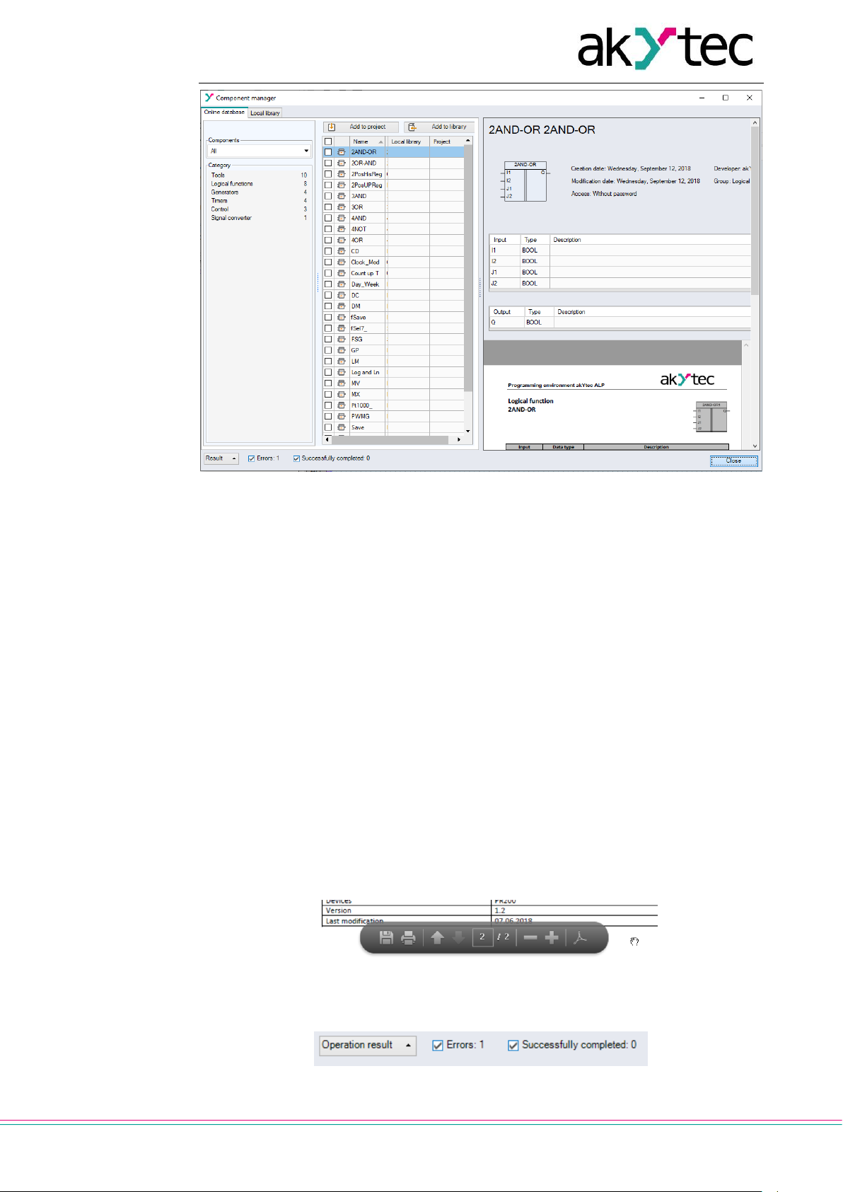
2.9 Component Manager
New macros and device templates can be downloaded from akYtec Online Database.
Component Manager is the tool for all interactions with this database. Select the menu
item File > Component Manager to open it in a separate window.
Page 17
User interface
akYtec GmbH · Vahrenwalder Str. 269 A · 30179 Hannover · Germany · Tel.: +49 (0) 511 16 59 672-0 · www.akytec.de
16
Fig. 2.21
The internet access is necessary for Component Manager to interact with Online Database.
The interface has two tabs: Online Database (sect. 2.9.1) and Local library (sect. 2.9.2).
Blocks are shown in categories and can be filtered by name.
2.9.1 Online Database
Add to project button – the selected blocks (macros or device templates) from
Online Database are added to the project library. The blocks are than stored in the
project file and can be viewed in Library Box (sect. 2.4) in the Project Macros area.
Add to library button – the selected blocks from Online Database are downloaded to
the local library and can then be used offline.
A check mark in the column Project or Library indicates that the block has been successfully downloaded / added.
Library files are stored at the local address:
C: \ Users \ [username] \ Documents \ akYtec ALP \ Library \
The brief description of the selected block is displayed in the upper right field, and the full
description in the lower right field. The full description is a PDF document. Scroll the document to the end to see the PDF toolbar. Using it, you can download the document or
print it.
Fig. 2.22
Click the button Operation result at the bottom of the window to view the program messages about the performed operations.
Fig. 2.23
Page 18

User interface
akYtec GmbH · Vahrenwalder Str. 269 A · 30179 Hannover · Germany · Tel.: +49 (0) 511 16 59 672-0 · www.akytec.de
17
2.9.2 Local library
Add to project button – the selected blocks (macros or device templates) from
Online Database are added to the project library. The blocks are saved in the project
file and can be viewed in the Library Box (sect. 2.4) in the Project Macros (sect. 6.3)
area.
Import button – the selected blocks are added from a file in the project library.
Export button – the selected blocks from the project library are saved as files un-
der the specified path.
Remove button – the selected blocks are removed from the local library.
Page 19
Usage basics
akYtec GmbH · Vahrenwalder Str. 269 A · 30179 Hannover · Germany · Tel.: +49 (0) 511 16 59 672-0 · www.akytec.de
18
3 Usage basics
To program the device, proceed as follows:
Start ALP
Create a new project for the selected target device or open an existing project (sect. 3.3)
Save the project on the PC
Test and debug the program in the simulation mode (sect. 7.11)
Upload the project to the connected device (sect. 3.7)
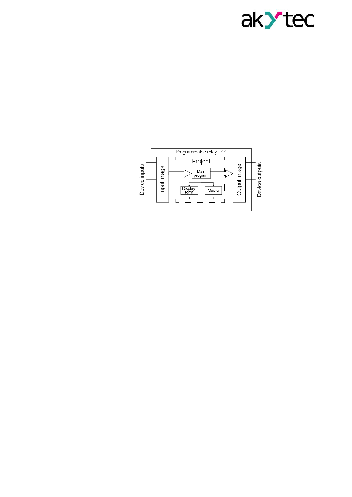
3.1 Program execution
The selected target device determines the number of available inputs and outputs and
the availability of a real-time clock. The general structure of the programmable relay is
shown in Fig. 3.1.
Fig. 3.1 PR operation flowchart
The programmable relay is a kind of PLC with a cyclically executed program:
Step 1 – The status of physical inputs is saved to the input memory cells (Input Image Table).
Step 2 – The input memory cells are read out and the program is executed from its first
instruction to the last one.
Step 3 – The results are saved to the output memory cells (Output Image Table) and ap-
plied to the outputs.
When the last step is completed, the program runs again from the first step.
3.2 Program cycle time
The cycle time is calculated by the device and depends on program complexity. The following blocks are especially resource-intensive:
FBs (sect. 6.2)
macros (sect. 6.3)
network variables (sect. 5.5)
display elements (sect. 6.4).
It is a read-only parameter and can be viewed on the device display (if exists) using the
system menu (see user guide). The minimum cycle time is 1 ms.
Note: The parameters Cycle time in device and in ALP simulation mode (sect. 7.11) are
different in spite of the same name.
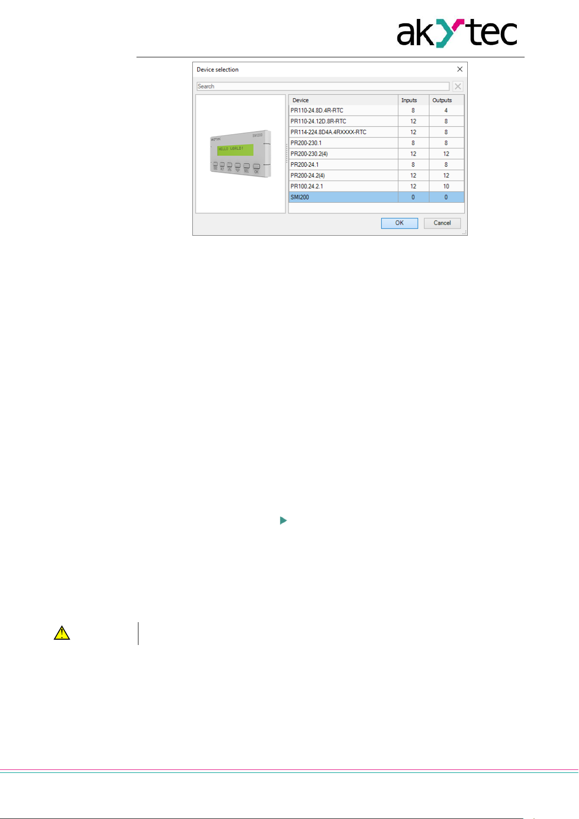
3.3 Project creation
To create a new project select File > New project in the main menu or use the equivalent
icon in the taskbar. Select the target device in the dialog window Device selection and
confirm it with OK (Fig. 3.2).
Page 20
Usage basics
akYtec GmbH · Vahrenwalder Str. 269 A · 30179 Hannover · Germany · Tel.: +49 (0) 511 16 59 672-0 · www.akytec.de
19
Fig. 3.2
The new project appearance:
workspace empty circuit program
status bar information about available resources
Library Box available program blocks
Property Box workspace properties.
Circuit program
Now you can create the main circuit program in the workspace using the common program blocks from the toolbar Insert and the specific program blocks from Library Box.
Draw connecting lines between inputs, outputs and program elements to establish logical
connections in the program. For details about individual program block and connecting
lines see sect. 7.
Display Manager
If the selected device has a display, the Display Manager tab appears to the left from the
workspace. With this tool you can program the displayed information.
Simulation
Program can be simulated offline. Start the simulation mode using the menu item Service
> Simulation or the toolbar icon , change the state of the inputs and notice the state of
the outputs to check the correctness of the program (sect. 7.11).
Online debugging
If the device is connected and the program in the device and in ALP is the same, you can
use online debugging to check the correctness of the program in the device (sect. 7.12).
3.4 Connection to device
WARNING
The device must be powered off before connecting to PC.
Devices can be connected to PC directly (PR200, SMI200) or over PR-KP20 adapter
(PR110, PR114). The required connection cable is included in the package of PR200 or
the adapter.
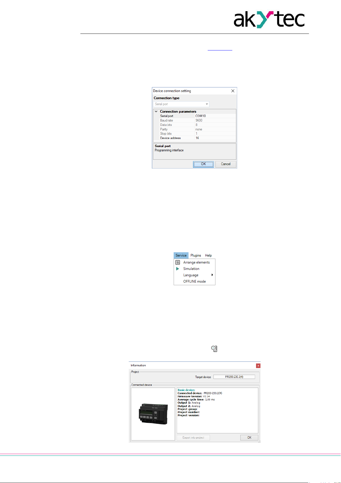
Connect the device to a USB port of the PC, switch the power on and select the serial
port in the menu Device > Port settings. The number of the emulated COM port can be
found in the Windows Device Manager under “Connections (COM and LPT)”.
Page 21
Usage basics
akYtec GmbH · Vahrenwalder Str. 269 A · 30179 Hannover · Germany · Tel.: +49 (0) 511 16 59 672-0 · www.akytec.de
20
If the operating system does not find the correct driver, install the driver for PR200 or for
the adapter PR-KP20. It can be downloaded from akytec.de.
Select the port number in the dialog window Port settings and confirm with OK. All other
settings are fixed and displayed only for your information.
If the connection is established, the information about the connected device and the serial
port is shown in the status indicators.
Fig. 3.3
3.4.1 OFFLINE mode
In this mode, the connection between ALP and the device is interrupted.
The mode is helpful when you work with two ALP instances running on PC and trying to
communicate with the same device. Both applications will alternately occupy the port and
the connection to the device will be constantly interrupted.
The application that should not communicate with the device should be switched to
OFFLINE mode.
Fig. 3.4
OFFLINE mode can be activated / deactivated using the menu item Service > OFFLINE
mode or by clicking the status indicator Device (sect. 2.7). With the next click is OF-
FLINE mode deactivated.
3.5 Device information
To view information about the software, the target device and the connected device use
the menu item Device > Information… or the icon in the toolbar.
Page 22
Usage basics
akYtec GmbH · Vahrenwalder Str. 269 A · 30179 Hannover · Germany · Tel.: +49 (0) 511 16 59 672-0 · www.akytec.de
21
Fig. 3.5
The window Device Information contains the following information:
Target device – the device for which the project was created
Connected device – the information about the device connected to the PC
Export into project – the button is active only if the device PR114-224.8D4A.4RXXXX is
connected. It can be used to export the real output types of the connected device into the
project. Alternatively the type of each output can be manually changed in Property Box
in accordance with the hardware.
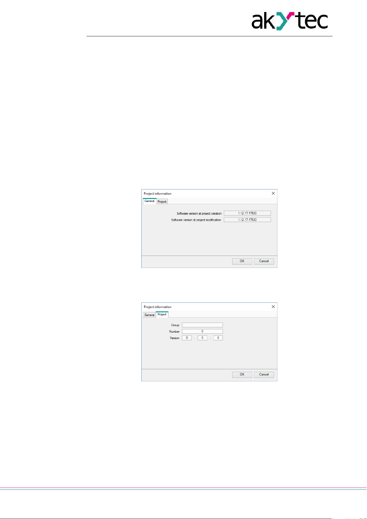
3.6 Project information
Use the menu item File > Project information to view and modify the information about
the project. The tab General contains the information about the version of the software.
Software version at project creation – the version of the software in which the project
has been created
Software version at project modification – the version of the software in which the pro-
ject has been modified
Fig. 3.6
The tab Project contains information about project version and is only for PR200 available.
Fig. 3.7
Group – project group name
Name – project number within a Group
Version – project version
After you complete the desired entries, confirm them with OK, or click Cancel to discard
them.
3.7 Upload project to device
Attention! The program already stored in the connected device will be replaced by the
new one.
Page 23
Usage basics
akYtec GmbH · Vahrenwalder Str. 269 A · 30179 Hannover · Germany · Tel.: +49 (0) 511 16 59 672-0 · www.akytec.de
22
Proceed as follows:
connect the device to PC
power on the device
adjust the port settings if necessary
upload the project to the device
The project can be uploaded to the device using the menu item Device > Transfer application to device or clicking the icon in the toolbar. When the upload is completed,
the device can be powered off and disconnected from the PC.
Fig. 3.8
If the target device does not match the connected device, a warning message will be displayed.
Note: After the program transfer is completed, the device goes to the operating mode and
the program starts automatically.
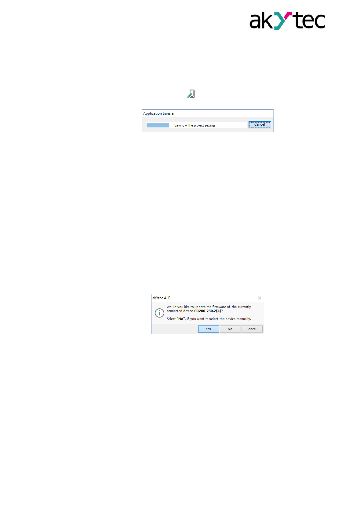
3.8 Firmware update / repair
If a new ALP version includes a new version of the firmware for the connected device or
extension module, you will be prompted to update the firmware before uploading a user
program to the device. No internet connection is needed. Click Yes to start the update.
Note: Ensure the power supply of the device and extension modules (if any) and the safe
connection between the PC, the device and the extension modules (if any) during the update process.
You can also update the firmware manually using the menu item Device > Firmware update. This way the firmware can be repaired when the firmware damage is detected (see
respective user guide, table “Error indication”).
Note: The user program will not be affected by firmware update.
Fig. 3.9
If you select Yes, the firmware of the currently connected and recognized device will be
updated (repaired).
If you select No, lists of devices and extension modules will be offered to select from (Fig.
3.10). The opened window has two tabs: Device and Extension Module. This way a
forced firmware update can be made (sect. 3.8.1).
Page 24

Usage basics
akYtec GmbH · Vahrenwalder Str. 269 A · 30179 Hannover · Germany · Tel.: +49 (0) 511 16 59 672-0 · www.akytec.de
23
Fig. 3.10
Click Select to confirm the selection and start the update (repair) process. The message
about the update result is shown upon the update completion.
3.8.1 Forced firmware update / repair
If the firmware is damaged (see respective user guide, table “Error indication”) and device
automatic recognition is not possible, a forced firmware update should be used. Proceed
as follows:
1. set the device in the forced download mode (see the device user guide)
2. select the menu item Device > Firmware update, lists of devices and extension
modules will be offered to select from
3. select the device (extension module)
4. click Select to confirm the selection and start the update (repair) process.
The message about the update result is shown upon the update completion.
If the basic device and the extension module have incompatible firmware versions and
the user program is uploaded to the basic device without the extension module connected, this may lead to an expansion module error displayed. To fix the error, use forced
firmware update for the expansion module as described, skipping step 1.
Page 25
Device configuration
akYtec GmbH · Vahrenwalder Str. 269 A · 30179 Hannover · Germany · Tel.: +49 (0) 511 16 59 672-0 · www.akytec.de
24
4 Device configuration
The configuration of the device is a part of a project and can be set using the menu item
Device > Configuration. The dialog window Device configuration consists of two parts.
The configurable parameters of the device are presented in the parameter tree in the left
part of the window. The content of a group is presented in the right part.
The content of the parameter tree depends on the target device and may include the following groups:
Display
Clock
Interfaces
Extension modules
Inputs
Outputs
All the settings are saved in the project, except the clock settings. The configuration is
also possible without connecting the device.
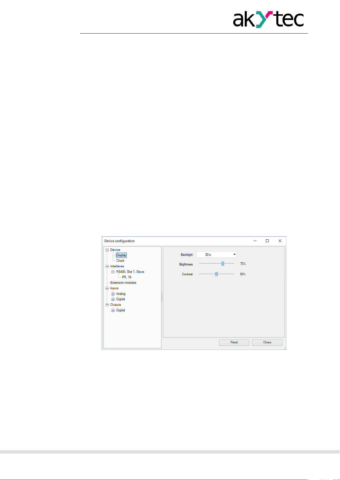
4.1 Display
If the target device has a display, the following parameters can be set:
Backlight – the duration of the backlight since the last user activity
Brightness – 0…100%
Contrast – 0…100%
The button Read can be used to read out the current display settings from the connected
device.
Fig. 4.1
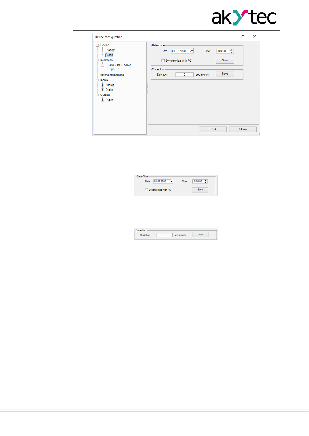
4.2 Clock
If the target device has a built-in real-time clock, the date and time can be set in the
Clock group.
Page 26
Device configuration
akYtec GmbH · Vahrenwalder Str. 269 A · 30179 Hannover · Germany · Tel.: +49 (0) 511 16 59 672-0 · www.akytec.de
25
Fig. 4.2
To synchronize the device clock with the PC clock, check the checkbox Synchronize
with PC. In this case the fields Date and Time become inactive. To set the device clock
to the new values click the button Save in the section Date/Time.
Fig. 4.3
Specify the clock error in seconds per month in the field Deviation to set the clock correction. Enter a negative value if the device clock is too fast.
Fig. 4.4
To save the clock correction in the device, click the button Save in the section Correction.
The button Read can be used to read the current time settings from the connected device.
4.3 Interfaces
If the target device has a serial network interface RS485, its parameters can be set in the
group Interfaces.
By default, there is one interface configured as a slave and assigned to the hardware slot
1 with the following settings: master device with the name PR and the network address
16.
If the number of interfaces on the target device can be changed, interfaces can be added
or deleted in the configuration, but their number cannot exceed the number of the existing
slots (sect. 4.3.2).
If an interface is configured as a master, slaves can be added to the configuration or removed, but their number may not exceed 16.
4.3.1 Modbus working
ALP can be used to program devices that support Modbus-RTU or Modbus-ASCII (master / slave) protocols.
Page 27
Device configuration
akYtec GmbH · Vahrenwalder Str. 269 A · 30179 Hannover · Germany · Tel.: +49 (0) 511 16 59 672-0 · www.akytec.de
26
Note: The devices PR110 and PR114 can operate only in the slave mode and only with
the PR-MI485 interface adapter.
In order to organize data exchange in the network over the RS485 interface, a master device is required. There can be only one master in the network.
Cycle time
The program execution time (cycle time) is automatically adjusted (auto-tuning) depending on the program complexity. The auto-tuning affects data exchange over Modbus,
since the program execution has a higher priority than request processing. If the program
is large, it can take up all the CPU time and Modbus data exchange will not be performed
correctly.
To avoid this problem, the lower limit for the volume of the Modbus data exchange is reserved: 50 requests per second. Thus, at least 50 requests per second can be executed
even if the user program is large, and even more if the program is small and the processor capacity is sufficient. If there is not enough time to poll all devices, the number of requests should be optimized in the user program.
The Query cycle setting depends on the number of polled variables and the polling frequency in the program. It is recommended to set Query cycle to 1 s. In this case, the device will be able to request up to 50 variables.
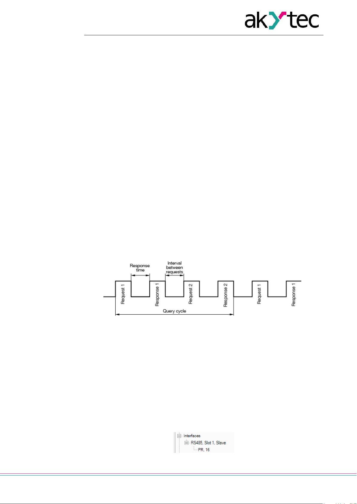
Query time
The query time is the actual time it takes the device to run all requests in a queue. If the
queue is short, the device will perform all the request-response cycles and wait for the
specified Query cycle to expire (Fig. 4.5). If the queue is long and the query takes longer
than the specified Query cycle, the device will poll all slaves in the shortest possible
time.
Fig. 4.5 Query time diagram
To minimize the request time, the following is recommended:
If one or several slaves are not connected or temporarily unavailable, consider to
block the polling in a program or to minimize the Timeout parameter for these devices.
Consider the number of slaves and the total number of requests when setting the
Query cycle parameter. If the processing time of all requests (query time) takes
longer than Query cycle, the parameter will be ignored.
Polling of multiple devices in the network
Slaves are polled according to the generated queue from the smallest to the largest ad-
dress. In the following example, the slave with the address 8 is polled first, with the address 32 last.
Fig. 4.6
Page 28

Device configuration
akYtec GmbH · Vahrenwalder Str. 269 A · 30179 Hannover · Germany · Tel.: +49 (0) 511 16 59 672-0 · www.akytec.de
27
Query cycle can be set for each slave individually.
4.3.2 Add / remove interface
If the device has a slot, for which no interface is configured, an appropriate interface can
be added using the item Add Interface in the context menu.
Fig. 4.7
An interface of the selected type with default settings is added.
Depending on device, the interface can be replaced by another type of interface or re-
moved using the context menu.
Fig. 4.8
Page 29
Device configuration
akYtec GmbH · Vahrenwalder Str. 269 A · 30179 Hannover · Germany · Tel.: +49 (0) 511 16 59 672-0 · www.akytec.de
28
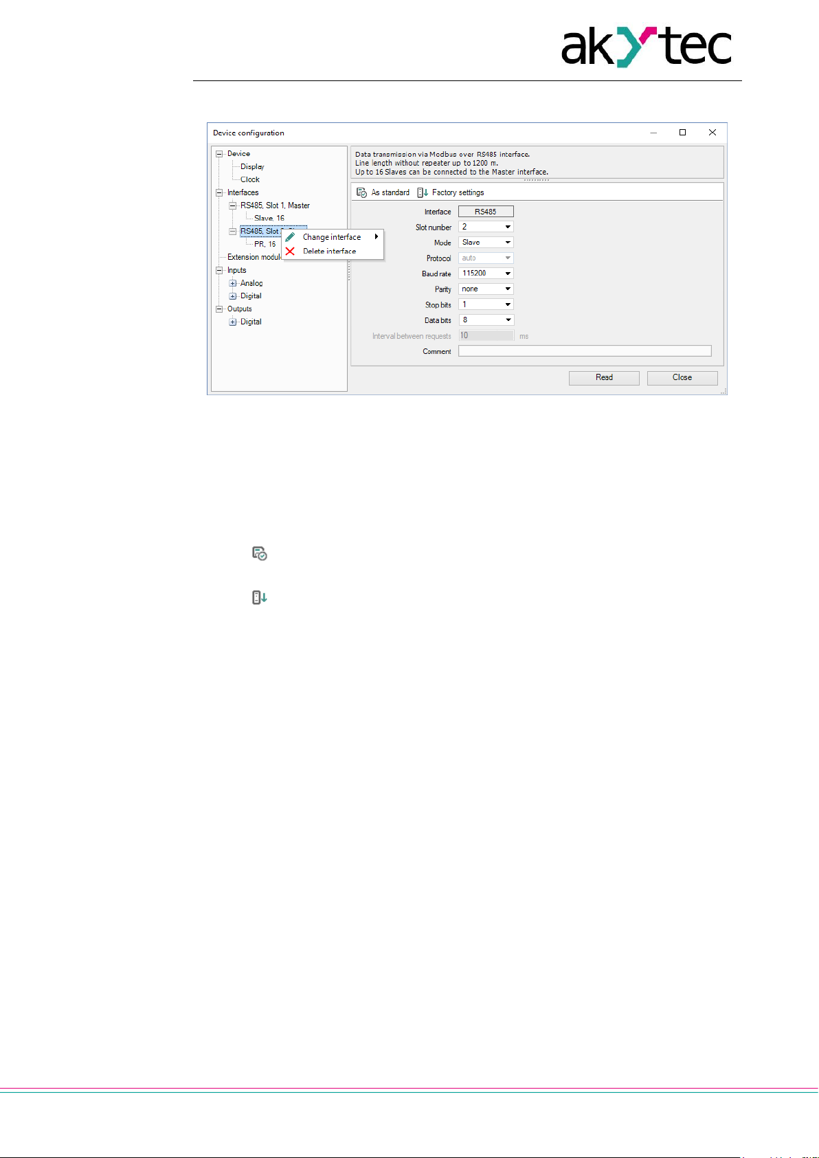
4.3.3 RS485 Interface configuration
Fig. 4.9 Interface configuration
The type of the interface (RS485), the number of the assigned slot and the mode (master
/ slave) are displayed in the tree.
To establish the connection over the interface, it has to be configured. The parameters of
the interface are displayed in the right part of the window. The default value depends on
the target device. The parameters Protocol and Interval between requests are only in
the master mode available. In the slave mode they are inactive and grayed out.
The icon As standard is used to save the settings as default values for future projects.
The icon Factory settings is used to apply the unchangeable factory settings.
The button Read is used to read out the current settings from the connected device.
Use the button Close to save the settings in the project and close the dialog.
4.3.3.1 Master mode
Each interface can control up to 16 slaves. Each slave supports up to 256 variables. The
addresses and names of the variables need only be unique if they belong to the same
slave.
In the master mode, all slaves connected to the interface are sequentially requested. Select the mode Master in the parameter list, set other connection parameters and add the
required number of slaves using the item Add slave in the interface context menu.
Page 30

Device configuration
akYtec GmbH · Vahrenwalder Str. 269 A · 30179 Hannover · Germany · Tel.: +49 (0) 511 16 59 672-0 · www.akytec.de
29
Fig. 4.10 Master configuration in master mode
The added slave device is displayed with its name and address in the tree below the interface. Select a slave to configure it in the right part of the window.
The parameters of the slave can be specified in the upper part of the window (Fig. 4.11).
To delete the slave, use the context menu or the icon Remove Slave.
Fig. 4.11 Slave configuration in master mode
Name – the name of the slave displayed in the tree
Address – the network address of the slave
Query cycle (ms) – the time interval between queries. A query comprises the num-
ber of requests according to the number of variables listed for the slave. The valid
range is 0…65535 ms.
Timeout (ms) – the time that request can take before the attempt is considered as
failed. The valid range is 0…65535 ms.
Page 31

Device configuration
akYtec GmbH · Vahrenwalder Str. 269 A · 30179 Hannover · Germany · Tel.: +49 (0) 511 16 59 672-0 · www.akytec.de
30
Retries, max. – the number of the failed request attempts before query is stopped
and the status of the device changes. The valid range is 0…255.
Burst request – group request of consecutive registers to increase the data through-
put
Status variable – select a BOOL variable using the icon to record the device sta-
tus:
o 1 – the device functions properly
o 0 – the device is not connected.
Start query – select a BOOL variable using the icon to control the query:
o 0 – query disabled
o 1 – query enabled.
Change register order – determines the register order in two-register variables
Change byte order – determines the byte order in the register
Comment – the text comment to describe the device
Fig. 4.12 Query time diagram
The list of the variables to be requested from this slave is in the lower part of the window.
Each variable created in this list can be found in the variable table under the tab Net-
work, Slot X with a separate list of variables (sect. 5.5) for each slave device.
Add a variable by clicking the icon New variable, and set its properties.
Fig. 4.13 Variable configuration in master mode
Name – the name of the variable
Type – the data type of the variable: BOOL, INT or REAL
Register – the register address
Bit – the number of the bit of the register (0…15) (only for BOOL variables)
Read function / Write function – selection of the read / write function or disable
reading / writing.
Number of registers – the number of registers occupied by the variable (only for INT
variables)
Page 32

Device configuration
akYtec GmbH · Vahrenwalder Str. 269 A · 30179 Hannover · Germany · Tel.: +49 (0) 511 16 59 672-0 · www.akytec.de
31
Start reading – assign the BOOL variable for forced reading of the requested varia-
ble
Start writing – assign the BOOL variable for forced writing of the requested variable
Status variable – assign the INT variable to record the error code
Comment – the text comment to describe the requested variable
To create several variables with the same settings, select a variable and click the icon
Duplicate.
Fig. 4.14 Variable duplication
Name – the name of the duplicated variable
Start number – the initial number to add to the name of the duplicated variable
Quantity – the quantity of the duplicated variables
Address step – the address increment
Click OK to add the duplicated variables to the list of variables. The variables will be
stored in adjacent register cells with consecutive addresses.
To remove the variable from the list, use the icon Delete.
4.3.3.2 Templates
A slave device in the configuration mask can be saved as a template, with its parameters
and variables, to be used in further projects. Use the context menu item or the icon
Save Slave as a template (Fig. 4.15). The template is saved as a file with the extension
*.dvtp.
Fig. 4.15 Slave context menu
A slave can be added to a master as a template using the context menu item Add from
templates… (Fig. 4.16).
Fig. 4.16 Master context menu
4.3.3.3 Slave mode
An RS485 interface added to the tree item Interfaces has the default mode Slave and
the default master with the name PR and the address 16 added below. Select the interface to set the connection parameters.
Page 33

Device configuration
akYtec GmbH · Vahrenwalder Str. 269 A · 30179 Hannover · Germany · Tel.: +49 (0) 511 16 59 672-0 · www.akytec.de
32
Fig. 4.17 Slave configuration in slave mode
Select the master in the tree to set the parameters for data exchange.
Fig. 4.18 Master configuration in slave mode
The common parameters for data exchange can be set in the upper window part.
Name – the name of the master displayed in the tree
Address – the network address of the master
Change register order – the register order in two-register variables
Change byte order – the byte order in the register
Comment – the text comment to describe the device
The list of the variables to be requested by the master is in the lower part of the window.
Each variable created in this list can be found in the variable table under the tab Net-
work, Slot X (sect. 5.5).
Add a variable by clicking the icon New variable and set its properties.
Fig. 4.19 Variable configuration in slave mode
Name – the name of the variable
Type – the data type of the variable: BOOL, INT or REAL
Register – the register address. The range of the available addresses is specified in
the device user guide.
Comment – the text comment to describe the requested variable
Page 34

Device configuration
akYtec GmbH · Vahrenwalder Str. 269 A · 30179 Hannover · Germany · Tel.: +49 (0) 511 16 59 672-0 · www.akytec.de
33
To create several variables with the same settings, select a variable and click the icon
Duplicate.
Fig. 4.20 Variable duplication
Name – the name of the duplicated variable
Start number – the initial number added to the name of the duplicated variable
Quantity – the quantity of the duplicated variables
Address step – the address increment
Click OK to add the duplicated variables to the list of variables. The variables will be
stored in adjacent register cells with consecutive addresses.
To remove the variable from the list, use the icon Delete.
4.4 Extension modules
Up to two I/O extension modules of type PRM can be connected to PR200. For further information about extension modules refer to the PRM user guide.
To use module I/O points in the circuit program, add the module to the group Extension
modules using its context menu (Fig. 4.21).
Fig. 4.21
The additional I/O points of the added modules can be configured in branches Inputs and
Outputs respectively (sect. 4.5, 4.6). They are displayed in the tree as Ix(y) and Qx(y)
respectively, where x is the ordinal number of the I/O points on the module and y is the
ordinal number of the module counting from the basic device.
Fig. 4.22
Before uploading the project to the basic device, all modules must be connected via the
internal bus to PR200 and powered on. The module firmware is synchronized with the
current version of ALP when project uploading.
4.5 Inputs
The content of the branch Inputs depends on the resources of the target device. It can be
analog and/or digital inputs (Fig. 4.23, 4.24).
Page 35

Device configuration
akYtec GmbH · Vahrenwalder Str. 269 A · 30179 Hannover · Germany · Tel.: +49 (0) 511 16 59 672-0 · www.akytec.de
34
The parameter Comment is common for all types of inputs. The text in this field is displayed in a tooltip, when the mouse is over the input in the workspace. The text can be
entered in Property Box too.
For further details about the configuration of the inputs, refer to the device user guide.
Fig. 4.23 PR200 digital input configuration
Other input parameters depend on the types of the input and the device.
Fig. 4.24 PR200 analog input configuration
4.6 Outputs
The content of the branch Outputs depends on the resources of the target device. It can
be analog and/or digital outputs (Fig. 4.24).
The parameter Comment is common for all types of outputs. The text in this field is displayed in a tooltip, when the mouse is over the output in the workspace. It can be entered
in Property Box too.
For further details about the configuration of the outputs, refer to the device user guide.
The digital outputs of the extension module have an additional parameter Safe condi-
tion. The parameter specifies the output state in case the connection between the module and the basic device is lost.
Fig. 4.25 PRM input configuration
Page 36

Device configuration
akYtec GmbH · Vahrenwalder Str. 269 A · 30179 Hannover · Germany · Tel.: +49 (0) 511 16 59 672-0 · www.akytec.de
35
4.7 Calibration
Only general information about calibration of analog inputs or outputs is given in this section. For detailed information about calibration refer to the user guide of the device.
If calibration of analog inputs or outputs is necessary, use the menu item Device > Cali-
bration….
The item is active only if a device is connected. Select the calibration target (inputs or outputs) in the opened dialog.
Fig. 4.26
After the calibration target selection, the execution of the program in the device is
stopped. The program starts again upon the successful completion of the calibration.
4.7.1 Input calibration
To calibrate inputs, connect a reference signal source to them. Start calibration, select the
type of signal connected to the input and set the calibration parameters in the opened dialog.
Fig. 4.27 PR200 input calibration
Use the item Reset settings to apply the default settings for calibration.
Use the list Select input to select the input to calibrate, click the button Next and follow
the instructions.
4.7.2 Output calibration
Before calibrating an analog output, prepare the appropriate measuring device, than start
calibration and follow the instructions. Measure the signal at the output indicated at the
top right of the window and enter the value in the input field.
Page 37

Device configuration
akYtec GmbH · Vahrenwalder Str. 269 A · 30179 Hannover · Germany · Tel.: +49 (0) 511 16 59 672-0 · www.akytec.de
36
Fig. 4.28 PR200 output calibration
Proceed the same way with the other outputs if needed. The message about the calibration results will appear after the completion of the calibration.
Fig. 4.29
4.8 Change target device
The target device of a project can be changed using the menu item File > Change target
device. A list of devices to which you can transfer the project appears. Select the device
and confirm with OK. Check and repair broken links, if any. The program can be checked
using simulation (sect. 7.11). Save the modified project.
Consider the replacement rules:
1. The workspace size will be automatically adjusted to the changed number of I/O
points.
2. User-configured layout of I/O points remains. New I/O points will be placed after existing I/O points of the original project.
3. The connections of I/O points whose data type has been changed will be removed.
4. If the number of I/O points becomes less than in the original project, the connections
of the removed I/O points will be also removed.
5. If there were extension modules in the original project, they will be transferred to the
new configuration with their connections.
6. Settings of analog I/O points will be transferred if there are analog I/O points on the
new device.
7. Network interfaces will be transferred unchanged.
8. Display settings will be transferred unchanged.
9. Variables will be transferred unchanged.
Page 38

Variables
akYtec GmbH · Vahrenwalder Str. 269 A · 30179 Hannover · Germany · Tel.: +49 (0) 511 16 59 672-0 · www.akytec.de
37
5 Variables
To see all project variables, click the icon in the toolbar or use the menu item Device >
Variable table.
The variables are divided into three groups, each of which has a separate tab in the table:
Standard (sect. 5.3)
Service (sect. 5.4)
Network (sect. 5.5)
Standard and network variables can be created, duplicated or deleted. The duplicated
variable is a copy of the selected variable saved in the next free register cell. Consecutive
indexes, starting with 2, will be added to the name of each duplicated variable.
To create a new variable, you can use:
toolbar icon
key combination Ctrl+N
or simply write a new variable name in the last row.
If you create a new variable after an unsuccessful search, the name entered in the search
field will be proposed as the name of the new variable.
To duplicate an existent variable you can use:
toolbar icon
key combination Ctrl+D
context menu item Duplicate
To delete a variable, you can use:
toolbar icon
key DEL
context menu item Delete
Service variables can neither be created nor deleted.
Fig. 5.1
The rows in the Variable Table can be sorted by each column.
5.1 Properties
Table 5.1 Variable properties
Name
The name of the variable
Data type
BOOL, INT or REAL (sect. 5.2)
Persistence
Only for standard variables available. The variable is stored in the
non-volatile memory of the device and become retain variable.
For detailed information about storage time and memory size, refer to the device user guide.
Default value
Only for retain and network variables available. It is the value at
the first start of the program, until the new value is assigned to.
Page 39

Variables
akYtec GmbH · Vahrenwalder Str. 269 A · 30179 Hannover · Germany · Tel.: +49 (0) 511 16 59 672-0 · www.akytec.de
38
Used in project
The variable has a reference to a block in the program
Comment
The text displayed in a tooltip in the workspace, when the mouse
is over the variable
5.2 Data type
The variables of the following types can be used in a program:
Boolean (BOOL)
Integer (INT)
Real (REAL)
Note: Different devices can have restrictions related to support of certain types of variables.
1. BOOL
A variable of this type has only two possible values: 1 (True) or 0 (False).
The connecting lines between the BOOL variables in the circuit program are displayed in
gray.
Fig. 5.2 BOOL connections
2. INT
A variable of this type is unsigned integer in the range 0…4,294,967,295 (4 Byte).
The connecting lines between the INT variables in the circuit program are displayed in
red.
Fig. 5.3 INT connections
3. REAL
A variable of this type has a value in the range -3.402823e+38…3.402823e+38. It is represented by a floating-point number of single-precision (4 Byte).
The connecting lines between the REAL variables in the circuit program are displayed in
violet.
Fig. 5.4 REAL connections
5.3 Standard variables
These are common variables used for data exchange between blocks of the circuit program, inputs, outputs and display forms.
Standard variables are listed in the variable table under the tab Standard.
Page 40

Variables
akYtec GmbH · Vahrenwalder Str. 269 A · 30179 Hannover · Germany · Tel.: +49 (0) 511 16 59 672-0 · www.akytec.de
39
To create a variable, select the empty row in the table, enter the variable name and select
its data type. Other parameters are optional. The created variable can be used in the project.
Use the item Show references in the variable context menu to see where the variable is
used in the project.
Fig. 5.5
In the dialog window References to the variable select the reference you want to delete
and click Delete.
To remove the variable from the table, use the item Delete variable in its context menu.
5.4 Service variables
Service variables are associated with the device settings and can differ, depending on the
device. Service variables are related to the hardware features, such as real-time clock,
interface card in the slot etc. and cannot be deleted. Access rights to service variables
may be limited.
The service variables are listed in the variable table under the tab Service.
The blocks of service variables are shown in the circuit program with a gray background.
Fig. 5.6 Service variables in the table
Fig. 5.7 Service variables in diagram
5.5 Network variables
Each interface slot has a separate tab in the table.
If the interface is configured as a master, there are separate tabs for each Slave device
within the slot tab (Fig. 5.8). The Slave tab contains the variables to be requested for this
Slave device.
Page 41

Variables
akYtec GmbH · Vahrenwalder Str. 269 A · 30179 Hannover · Germany · Tel.: +49 (0) 511 16 59 672-0 · www.akytec.de
40
Fig. 5.8 Network variables for master interface
Network variables and their references are deleted in the same way as standard variables
(sect. 5.3).
For more details about network variables for master interface see sect. 4.3.3.1.
If the interface is configured as a Slave, all network variables to be requested by the mas-
ter are shown in one list (Fig. 5.9). For more details about network variables for Slave interface see sect. 4.3.3.3.
Fig. 5.9 Network variables for Slave interface
5.6 Copy / paste variable block
The variable blocks can be copied and pasted into another project.
To copy a variable block, select it in the workspace and use the toolbar icon or the
item Copy in the block context menu.
To paste a variable block into another project, open it in the second ALP instance and
use the toolbar icon or the item Paste in the workspace context menu.
Copy rules for all variables associated with the block:
If the variable associated with the block is unique in the second project, it will be
added with all properties to the variable table.
If there is an identical variable in the second project, it will be associated with the
pasted block. No new variables will be added to the variable table.
If the second project has a variable with the same name but different parameters, a
new variable will be created. To resolve the naming conflict, the name of one of the
variables should be changed manually.
It is not possible to insert variables of REAL type into a project for a target device that
does not support REAL data type.
Retain (persistent) variables cannot be copied into a project for a target device that
does not support them.
Copy rules for service variables:
Service variables cannot be copied to a project written to a target device without a
real-time clock.
Page 42

Variables
akYtec GmbH · Vahrenwalder Str. 269 A · 30179 Hannover · Germany · Tel.: +49 (0) 511 16 59 672-0 · www.akytec.de
41
Copy rules for network variables:
Only the variables of a slave interfaces can be copied into another project and the in-
terfaces in both projects must have the same slot numbers. The variables of the master interface variables should be created manually.
Any register conflict must be resolved manually.
Page 43

Library
akYtec GmbH · Vahrenwalder Str. 269 A · 30179 Hannover · Germany · Tel.: +49 (0) 511 16 59 672-0 · www.akytec.de
42
6 Library
If a project is open, the panel Library Box contains the following libraries:
Functions
Function blocks
Project macros
Select an icon in the lower part of the panel to show the respective content.
The library Project macros comprises the macros that have been created, imported or
included to the project from Online Database.
View options can be changed using the icons located in the toolbar of the panel.
6.1 Functions
The library contains the following function groups:
Logical operators
Mathematical operators
Relational operators
Bitshift operators
Bit operators
6.1.1 Logical operators
Conjunction (AND)
Disjunction (OR)
Negation (NOT)
Exclusive OR (XOR)
The logical operators can operate with BOOL or INT variables.
If the input values are INT, the operation is bitwise performed and the output is also an
INT.
6.1.1.1 Conjunction (AND)
Fig. 6.1
The output Q is True if both inputs are True. The function AND represents a serial connection in an electrical circuit.
Table 6.1 Truth table
I1
I2 Q 0 0 0
0 1 0 1 0
0
1 1 1
Bitwise operation example with integer inputs:
0101 (decimal 5)
AND 0011 (decimal 3)
= 0001 (decimal 1)
Page 44

Library
akYtec GmbH · Vahrenwalder Str. 269 A · 30179 Hannover · Germany · Tel.: +49 (0) 511 16 59 672-0 · www.akytec.de
43
6.1.1.2 Disjunction (OR)
Fig. 6.2
The output Q is True if at least one of the inputs is True. The function OR represents a
parallel connection in an electrical circuit.
Table 6.2 Truth table
I1
I2
Q
0 0 0 0 1 1 1 0 1 1 1
1
Bitwise operation example with integer inputs:
0101 (decimal 5)
OR 0011 (decimal 3)
= 0111 (decimal 7)
6.1.1.3 Negation (NOT)
Fig. 6.3
The function NOT inverts the signal. The output Q is True if the input is False and vice
versa.
Table 6.3 Truth table
I1 Q 0
1
1
0
Bitwise operation example with integer inputs:
NOT 0111 (decimal 7)
= 1000 (decimal 8)
The bitwise NOT, or complement, is a unary operation that performs logical negation on
each bit, forming the ones' complement of the given binary value.
Page 45

Library
akYtec GmbH · Vahrenwalder Str. 269 A · 30179 Hannover · Germany · Tel.: +49 (0) 511 16 59 672-0 · www.akytec.de
44
6.1.1.4 Exclusive OR (XOR)
Fig. 6.4
The output Q is True if only one of the inputs is True.
Table 6.4 Truth table
I1
I2
Q
0 0 0 0 1 1 1 0 1 1 1
0
Bitwise operation example with integer inputs:
0101 (decimal 5)
XOR 0011 (decimal 3)
= 0110 (decimal 6)
6.1.2 Mathematical operators
There are different operators for different data types:
Table 6.5
Operator
INT
REAL
Addition
ADD
fADD
Subtraction
SUB
fSUB
Multiplication
MUL
fMUL
Division
DIV
fDIV
Modulo operation
MOD
-
Power function
-
fPOW
Absolute value - fABS
6.1.2.1 Addition (ADD, fADD)
Fig. 6.5
The function ADD operates with INT variables, the function fADD operates with REAL
variables.
The output value Q is the sum of the input values.
Example:
Page 46

Library
akYtec GmbH · Vahrenwalder Str. 269 A · 30179 Hannover · Germany · Tel.: +49 (0) 511 16 59 672-0 · www.akytec.de
45
Fig. 6.6
The output value may not exceed 4294967295 (32 bits). Otherwise the extra bits will be
truncated.
6.1.2.2 Subtraction (SUB, fSUB)
Fig. 6.7
The function SUB operates with INT variables, the function fSUB operates with REAL
variables.
The output value Q is the result of subtraction of the value I2 from the value I1.
Example 1:
Fig. 6.8
If the value I1 is less than the value I2, the output is calculated as follows:
Q = I1 + 0x100000000 – I2
0x100000000 = 4294967296
Example 2:
Fig. 6.9
6.1.2.3 Multiplication (MUL, fMUL)
Fig. 6.10
The function MUL operates with INT variables, the function fMUL operates with REAL
variables.
The output value Q is the product of the input values.
Example:
Page 47
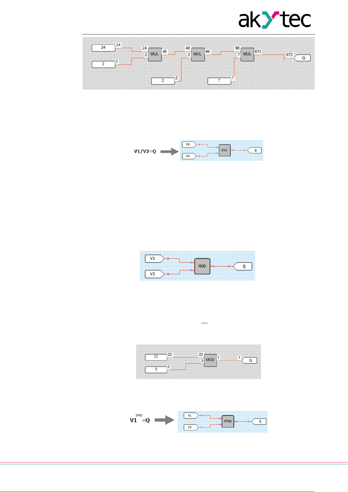
Library
akYtec GmbH · Vahrenwalder Str. 269 A · 30179 Hannover · Germany · Tel.: +49 (0) 511 16 59 672-0 · www.akytec.de
46
Fig. 6.11
The output value may not exceed 4294967295 (32 bits). If it does happen, the extra bits
will be truncated.
6.1.2.4 Division (DIV, fDIV)
Fig. 6.12
The function DIV operates with INT variables, the function fDIV operates with REAL variables.
The output value Q is the quotient of the input values, where the value I1 is the dividend
and the value I2 is the divisor.
If the quotient is not an INT, it is rounded down to an INT.
In case of division by 0 the output value is 0xFFFFFFFF.
6.1.2.5 Modulo operation (MOD)
Fig. 6.13
The function MOD operates with INT variables. The output Q is a remainder of the division of input values.
𝑄 = [
𝑉1
𝑉2
]
Example:
Fig. 6.14
6.1.2.6 REAL-Power function (fPOW)
Fig. 6.15
The function fPOW operates with REAL variables.
Page 48

Library
akYtec GmbH · Vahrenwalder Str. 269 A · 30179 Hannover · Germany · Tel.: +49 (0) 511 16 59 672-0 · www.akytec.de
47
The output value Q is the value I1 raised to the power of the value I2.
Example:
Fig. 6.16
6.1.2.7 REAL-Absolute function (fABS)
Fig. 6.17
The function fABS operates with REAL variables.
The output value Q is an absolute value of the input value.
𝑄 =|𝑉|
Examples:
Fig. 6.18
6.1.3 Relational operators
The relational operators are functions that test or define some kind of relation between
two or more values.
6.1.3.1 Equal (EQ)
Fig. 6.19
The function EQ operates with INT variables.
The output value Q is True if the value I1 and the value I2 are equal.
Table 6.6 Truth table
I1 / I2
Q
I1 = I2
1
I1 > I2
0
I1 < I2
0
Examples:
Page 49

Library
akYtec GmbH · Vahrenwalder Str. 269 A · 30179 Hannover · Germany · Tel.: +49 (0) 511 16 59 672-0 · www.akytec.de
48
Fig. 6.20
6.1.3.2 Greater than (GT, fGT)
Fig. 6.21
The function GT operates with INT variables, the function fGT operates with REAL variables.
The output value Q is True if the value I1 is greater than the value I2.
Table 6.7 Truth table
I1 / I2
Q
I1 = I2
0
I1 > I2
1
I1 < I2
0
Examples:
Fig. 6.22
6.1.3.3 Binary selection (SEL)
Fig. 6.23
The function SEL operates with INT variables, the function fSEL operates with REAL variables.
If I1 = False, the output value Q is set to the value I2, else to the value I3.
Page 50

Library
akYtec GmbH · Vahrenwalder Str. 269 A · 30179 Hannover · Germany · Tel.: +49 (0) 511 16 59 672-0 · www.akytec.de
49
Table 6.8 Table of states
I1
Q
0
I2
1
I3
Examples:
Fig. 6.24
6.1.4 Bitshift operators
The bitshift operators treat a variable as a series of bits that can be moved (shifted) to the
left or right.
6.1.4.1 Shift register left (SHL)
Fig. 6.25
The function SHL operates with INT variables. It is used to shift all bits of the operand X
to the left by the N number of bits; vacated bits are zero-filled. The result is set to the out-
put Q.
Fig. 6.26
Example: left shift of the number 38 (decimal) = 00100110 (binary) by 2 bits
Fig. 6.27
Page 51

Library
akYtec GmbH · Vahrenwalder Str. 269 A · 30179 Hannover · Germany · Tel.: +49 (0) 511 16 59 672-0 · www.akytec.de
50
6.1.4.2 Shift register right (SHR)
Fig. 6.28
The function SHR operates with INT variables. It is used to shift all bits of the operand X
to the right by the N number of bits; vacated bits are zero-filled. The result is set to the
output Q.
Example: right shift of the number 152 (decimal) = 10011000 (binary) by 2 bits
Fig. 6.29
6.1.5 Bit operators
The bit operator treats a value as a series of bits to perform operations on one or more
individual bits of an operand.
6.1.5.1 Read single bit (EXTRACT)
Fig. 6.30
The output value Q (BOOL) of the function EXTRACT is the value of bit N (INT) in the operand X (INT). The bit numbering is zero-based.
Example: reading of the 5th bit from the number 81 (decimal) = 1010001 (binary):
Fig. 6.31
6.1.5.2 Set single bit (PUTBIT)
Fig. 6.32
This output value Q (INT) is the value of the operand X (INT) where the bit N (INT) is set
to the value at the input B (BOOL). The bit numbering is zero-based.
Page 52

Library
akYtec GmbH · Vahrenwalder Str. 269 A · 30179 Hannover · Germany · Tel.: +49 (0) 511 16 59 672-0 · www.akytec.de
51
Example: setting of the 4th bit to 1 in the number 38 (decimal) = 100110 (binary):
Fig. 6.33
6.1.5.3 Decoder (DC32)
Fig. 6.34
The decoder converts a binary code at the input to a position code at the output.
Decoding is carried out bitwise by the logical operation AND with the operand 0x1F
(11111b).
Table 6.9 Truth table
Binary code
Position code
5 4 3 2 1
32
31 … 6 5 4 3 2
1
0 0 0 0 0 0 0 0 0 0 0 0 1 0 0 0 0 1 0 0 0 0 0 0 1
0
0 0 0 1 0 0 0 0 0 0 1 0 0
0 0 0 1 1 0 0 0 0 1 0 0 0 0 0 1 0 0 0 0 0 1 0 0 0
0 … …
…
1 1 1 0 1 0 0 0 0 0 0 0 0 1 1 1 1 0 0 1 0 0 0 0 0 0 1 1 1 1 1 1 0 0 0 0 0 0 0
Example:
Fig. 6.35
6.1.5.4 Encoder (CD32)
Fig. 6.36
The encoder converts a position code at the input to a binary code at the output.
If there is more than one “1” bits in the position code, the encoder operates only with the
most significant “1” bit.
For truth table see table 6.9 for Decoder.
Page 53

Library
akYtec GmbH · Vahrenwalder Str. 269 A · 30179 Hannover · Germany · Tel.: +49 (0) 511 16 59 672-0 · www.akytec.de
52
6.2 Function blocks
The library contains the following FB groups:
Triggers
Timers
Generators
Counters
Control
6.2.1 Triggers
RS trigger reset dominant (RS)
SR trigger set dominant (SR)
Rising edge (RTRIG)
Falling edge (FTRIG)
D-trigger (DTRIG)
6.2.1.1 RS trigger reset dominant (RS)
Fig. 6.37
The output Q is True with a rising edge at the input S (Set) and False with a rising edge
at the input R (Reset). The input R has higher priority.
Fig. 6.38
6.2.1.2 SR trigger set dominant (SR)
Fig. 6.39
The output Q is True with a rising edge at the input S (Set) and False with a rising edge
at the input R (Reset). The input S has higher priority.
Fig. 6.40
Page 54

Library
akYtec GmbH · Vahrenwalder Str. 269 A · 30179 Hannover · Germany · Tel.: +49 (0) 511 16 59 672-0 · www.akytec.de
53
6.2.1.3 Rising edge (RTRIG)
Fig. 6.41
Detector for a rising edge
The output Q remains False until a rising edge at the input I. As soon as the input I be-
comes True, the output becomes also True and remains for one program cycle.
Fig. 6.42
6.2.1.4 Falling edge (FTRIG)
Fig. 6.43
Detector for a falling edge
The output Q remains False until a falling edge at the input I. As soon as the input I be-
comes False, the output becomes True and remains for one program cycle.
Fig. 6.44
6.2.1.5 D-trigger (DTRIG)
Fig. 6.45
D-trigger generates a pulse at the output Q with the pulse duration specified at the input
D and synchronized with the clock pulse at the input С.
If the input D is True, the output Q becomes True with a rising edge of the clock pulse at
the input C.
If the input D is False, the output Q becomes False with a rising edge of the clock pulse
at the input С.
Page 55

Library
akYtec GmbH · Vahrenwalder Str. 269 A · 30179 Hannover · Germany · Tel.: +49 (0) 511 16 59 672-0 · www.akytec.de
54
Fig. 6.46
The output Q can be forced set to True with a rising edge at the input S (Set) and forced
reset to False with a rising edge at the input R (Reset), regardless of the states of the inputs C and D. The input R has higher priority.
6.2.2 Timers
Pulse (TP)
ON-delay timer (TON)
OFF-delay timer (TOF)
Timer (CLOCK)
Weekly timer (CLOCKW)
6.2.2.1 Pulse (TP)
Fig. 6.47
The block TP is used to generate one output pulse with the specified pulse duration.
Fig. 6.48
The output Q becomes True with a rising edge at the input I for the time specified at the
input T. During this time, the output Q remains True regardless of the signal change at
the input I. The output Q is reset to False with the end of pulse.
The pulse duration and the time unit can be set in Property Box.
Fig. 6.49
Time range: 0…4147200000 ms or 48 days.
Page 56

Library
akYtec GmbH · Vahrenwalder Str. 269 A · 30179 Hannover · Germany · Tel.: +49 (0) 511 16 59 672-0 · www.akytec.de
55
6.2.2.2 ON-delay timer (TON)
Fig. 6.50
Fig. 6.51
The output Q = False if the input I = False. The delay time specified at the input TON
starts with a rising edge at the input I. When the time TON is elapsed, the output Q becomes True and remains until a falling edge at the input I. Input changes shorter than TON
are ignored.
The delay time and the time unit can be set in Property Box.
Fig. 6.52
Time range: 0…4147200000 ms or 48 days.
6.2.2.3 OFF-delay timer (TOF)
Fig. 6.53
The output Q = False if the input I = True. The delay time specified at the input T
OFF
starts with a falling edge at the input I. When the time T
OFF
is elapsed, the output Q be-
comes False and remains until a rising edge at the input I. Input changes shorter than
T
OFF
are ignored.
The delay time and the time unit can be set in Property Box.
Fig. 6.54
Time range: 0…4147200000 ms or 48 days.
Page 57

Library
akYtec GmbH · Vahrenwalder Str. 269 A · 30179 Hannover · Germany · Tel.: +49 (0) 511 16 59 672-0 · www.akytec.de
56
6.2.2.4 Timer (CLOCK)
Fig. 6.55
The block CLOCK is an interval timer controlled by a real-time clock.
Fig. 6.56
The times TH and TL can be set in Property Box.
Fig. 6.57
Time range: from 0.00 seconds to 24 hours.
If TH < TL, the state of the output Q is as follows:
Fig. 6.58
6.2.2.5 Week timer (CLOCKW)
Fig. 6.59
The block CLOCKW is an interval timer with the parameter Weekday controlled by a
real-time clock.
Fig. 6.60
The times TH and TL can be set in Property Box.
Page 58

Library
akYtec GmbH · Vahrenwalder Str. 269 A · 30179 Hannover · Germany · Tel.: +49 (0) 511 16 59 672-0 · www.akytec.de
57
Fig. 6.61
Time range: from 0.00 seconds to 24 hours.
6.2.3 Generators
Pulse generator (BLINK)
6.2.3.1 Pulse generator (BLINK)
Fig. 6.62
If the input I becomes True, the block BLINK generates a square wave on the output Q
with a period of TH + TL, starting with an interval of the duration of TL, followed by a pulse
of the duration of TH. It continues that way until the input I is False.
Fig. 6.63
The times TH and TL and the time units can be set in Property Box.
Fig. 6.64
Time range: 0…4233600000 milliseconds or 49 days.
6.2.4 Counters
Threshold counter with self-reset (CT)
Universal counter (CTN)
Threshold counter (CTU)
Page 59

Library
akYtec GmbH · Vahrenwalder Str. 269 A · 30179 Hannover · Germany · Tel.: +49 (0) 511 16 59 672-0 · www.akytec.de
58
6.2.4.1 Threshold counter with self-reset (CT)
Fig. 6.65
The output Q is of type BOOL. If the number of pulses counted on the input C exceeds
the threshold (Setting) specified at the input N, the output Q becomes True and remains
for one program cycle.
Fig. 6.66
The parameters Setting and State saving can be set in Property Box.
Fig. 6.67
Threshold range: 0…65535.
If State saving = Yes, the state of the counter is permanently stored in the non-volatile
memory.
6.2.4.2 Universal counter (CTN)
Fig. 6.68
The output Q is of type INT. A rising edge at the input U increases the value at the output
Q by 1. A rising edge at the input D decreases the value at the output Q by 1.
If the input R = True, the output Q becomes the value Setting at the input N.
Page 60

Library
akYtec GmbH · Vahrenwalder Str. 269 A · 30179 Hannover · Germany · Tel.: +49 (0) 511 16 59 672-0 · www.akytec.de
59
Fig. 6.69
The input U has higher priority than the input D.
The parameters Setting and State saving can be set in Property Box.
Fig. 6.70
Setting range: 0…65535.
If State saving = Yes, the state of the counter is permanently stored in the non-volatile
memory.
6.2.4.3 Threshold counter (CTU)
Fig. 6.71
The output Q is of type Boolean. If the number of pulses counted on the input C exceeds
the threshold (Setting) specified at the input N, the output Q becomes True and remains
until a rising edge at the input R. The input R has higher priority than the input C.
Fig. 6.72
The parameter Setting can be set in Property Box.
Fig. 6.73
Page 61

Library
akYtec GmbH · Vahrenwalder Str. 269 A · 30179 Hannover · Germany · Tel.: +49 (0) 511 16 59 672-0 · www.akytec.de
60
Threshold range: 0…65535.
6.2.5 Analog
PID controller (PID)
6.2.5.1 PID controller (PID)
Fig. 6.74
Fig. 6.75
The function block PID is used for implementation of the proportional-integral-derivative
control.
Table 6.10 PID block inputs/outputs
Name
Type
I/O
Description
Values
E
BOOL
I
Enable control (0 = Off, 1 = On). If disabled, the parameter
Pwr takes the value of the parameter Output safe state.
0/1
Pv
REAL
I
Process value
Sp
REAL
I
Setpoint
Pwr
REAL
O
Output power, %
0…100
Table 6.11 PID block parameters
Name
Type
Description
Values
Access
Property
Box
Write
ToFB
Read
FromFB
Control mode
BOOL
0 – Heating
0/1
Output safe
state
REAL
Output value when control is disabled, %
0…100
Kp
REAL
Proportional gain, multiplication factor for proportional control
0…100
Ti (s)
REAL
Integral time, time constant for integral control in seconds
-3.402823e+38…
3.402823e+38
Td (s)
REAL
Derivative time, time constant for derivative control in seconds
-3.402823e+38…
3..402823e+38
Output max.
REAL
Output upper limit, % (default 80)
0…100
Output min.
REAL
Output lower limit, % (default 20)
0…100
Start AT
BOOL
0 – stop auto-tuning
1 – start auto-tuning
0/1
Page 62

Library
akYtec GmbH · Vahrenwalder Str. 269 A · 30179 Hannover · Germany · Tel.: +49 (0) 511 16 59 672-0 · www.akytec.de
61
Name
Type
Description
Values
Access
Property
Box
Write
ToFB
Read
FromFB
AT completed
BOOL
Flag: 0 – auto-tuning stopped
1 – auto-tuning started
0/1
Kp calculated
REAL
Calculated proportional gain
0…100
Ti calculated
REAL
Calculated integral time
-3.402823e+38…
3.402823e+38
Td calculated
REAL
Calculated derivative time
-3.402823e+38…
3.402823e+38
Tuning of a control loop is the adjustment of its control parameters (Kp, Ti, Td) to the optimum values for the desired control response.
Programmable tuning
Programmable loop tuning can be performed using the blocks WriteToFB and ReadFromFB (sect. 7.7).
To write the parameters, use the block WriteToFB (Fig. 6.76) or Property Box (Fig. 6.77).
To read the parameters, use the block ReadFromFB (Fig. 6.76).
Fig. 6.76
Fig. 6.77
Auto-tuning
To use auto-tuning, add the block WriteToFB to the circuit program and set the reference
to the parameter Start AT of the PID block.
To start the auto-tuning, enable control (E = 1) and set the parameter Start AT = 1.
Page 63

Library
akYtec GmbH · Vahrenwalder Str. 269 A · 30179 Hannover · Germany · Tel.: +49 (0) 511 16 59 672-0 · www.akytec.de
62
Fig. 6.78
Upon completion of the auto-tuning, the new values of the parameters Kp, Ti and Td are
calculated and the flag AT completed becomes 1.
If Start AT = 0, the flag AT completed = 0 as well.
If you set Start AT = 0 before the completion of auto-tuning, the auto-tuning is stopped,
the flag AT completed becomes 0 and no new coefficients are calculated.
During the auto-tuning, a test signal limited by parameters Output max. and Output min.
is applied to the output Pwr.
Note: If the maximum gain is not sufficient to reach the setpoint, the auto-tuning cannot
be completed and will continue until it is stopped with Start AT = 0.
6.3 Project macros
Macro is a function block created like a main program in a separate workspace.
To create a new macro:
use the menu item File > New macro (sect. 6.3.3) or
select blocks in the main workspace and use the item New macro from the work-
space context menu (sect. 6.3.4)
To use the macro in the project, drag-and-drop it from Library Box into the main workspace.
Fig. 6.79
To open the project macro in the separate workspace for editing, select it in the workspace or in the library and use the item Edit macro in the macro context menu.
Fig. 6.80
Page 64

Library
akYtec GmbH · Vahrenwalder Str. 269 A · 30179 Hannover · Germany · Tel.: +49 (0) 511 16 59 672-0 · www.akytec.de
63
The macro can be saved in the project under another name using the menu item File >
Save macro as…. The saved macro is available only in this project.
Fig. 6.81
If the macro should be used in other projects, it must be saved as a file i.e. exported, and
then imported from this file into another project (sect. 6.3.1).
If a macro used in the project is changed, it will be displayed in red in the program and
the user will be prompted to update the macro (sect. 6.3.5).
Fig. 6.82 Macro update request
6.3.1 Export, import, download macro
A macro can be exported to a file when the macro workspace is active.
Open the macro for editing, use the menu item File > Export Macro, specify the file
name and the path and confirm with OK. The macro file has the extension *.tpl.
A macro can be imported from the file into the library if the main program is active. Use
the menu item File > Import macro, select the file in the opened dialog and confirm it
with OK. The macro is added to the library into the section Macros.
To download macros from Online Database, an internet connection is needed. Select the
menu item File > Component Manager (the main workspace must be active) to open
Component Manager in a separate window (sect. 2.9).
6.3.2 FB in macro
If a function block is used in the macro, the user can define whether the FB parameters
are available as parameters of the macro in the main program.
If the parameter Use in macro is set to Yes, the FB parameters became parameters of
the macro and a new option Parameters of macro is added to the macro. With this option, the user can specify the name for each FB parameter in the macro to use in the
main program.
Fig. 6.83
Page 65

Library
akYtec GmbH · Vahrenwalder Str. 269 A · 30179 Hannover · Germany · Tel.: +49 (0) 511 16 59 672-0 · www.akytec.de
64
6.3.3 New macro using main menu
Select the item File > New macro in the main menu. Specify the number of inputs and
outputs in the opened dialog and confirm with OK. The new empty macro is opened in a
separate workspace.
Fig. 6.84
The number of inputs and outputs can be always changed using workspace context
menu.
Fig. 6.85
To remove an input or an output, use Delete in its context menu.
The data type for each input and output can be selected in Property Box.
Fig. 6.86
Give a name, a description and a group to the macro in Property Box.
Fig. 6.87
Page 66

Library
akYtec GmbH · Vahrenwalder Str. 269 A · 30179 Hannover · Germany · Tel.: +49 (0) 511 16 59 672-0 · www.akytec.de
65
The name is displayed in the workspace tab. It is the name of the macro in the project.
The text in the parameter Description is displayed in a tooltip, when the mouse is over
the macro in the workspace.
The name in the parameter Group is used in the library. If the group name is empty, the
macro is assigned to the group Other in the project library.
If you set the password for the macro, it will be asked every time the menu item Edit
macro is selected.
6.3.4 New macro using context menu
You can create a macro by drawing a selection rectangle in the workspace and using the
item New macro from the workspace context menu. All selected blocks will be moved
into a new macro block that will replace the selected blocks in the workspace. All external
connecting lines will be retained.
Fig. 6.88
There are some specific aspects of creating macros using context menu:
The number of inputs and outputs of the macro is equal to the number of connected
input and output connections in the selected area. In case the elements without connections are selected, the macro with one input and one output will be created.
If a block of the standard variable is selected, the variable will be copied under the
same name into the macro.
Note: Despite the same name, the variables in the macro and in the main program are different, there is no conflict between them.
If all blocks of the variable are selected and it has no other references in the program,
the variable will be moved into the macro.
If the selected variable is used (has blocks or other references) outside the selected
area, it will be copied under the same name into the macro and the original will remain in the workspace.
If only one block of the input or output variable is selected, the variable will be copied
under the same name into the macro and the original will remain in the workspace.
When the macro is created using the context menu, the following elements will not be
included in it:
Page 67

Library
akYtec GmbH · Vahrenwalder Str. 269 A · 30179 Hannover · Germany · Tel.: +49 (0) 511 16 59 672-0 · www.akytec.de
66
o device inputs and outputs
o service variables
o network variables
o PID controller
In case the above mentioned blocks are selected, they will remain in the main work-
space and will be connected to the corresponding I/O points of the macro.
If any WriteToFB / ReadFromFB blocks (sect. 7.7) are assigned to the selected FB,
they will be included to the macro, even if they are not selected. If the read/write
blocks are selected but not the assigned FB, they will not be included in the macro.
6.3.5 Update macro
If the macro used in the program has been modified, (name, type, number of I/O points,
or the parameter Use in macro of any block), it will be displayed in red in the program
and the user will be prompted to update the macro. A macro is considered to be modified
after the changes made in Macro Editor are saved.
To update the macro, use its context menu.
Fig. 6.89
Once the macro has been updated, the next modified macro will be prompted to update.
Update rules:
If the type or name of the macro I/O points with the attached connection is changed,
the connection will be disconnected after the update.
If I/O points are added to the macro, the existing I/O points will not be disconnected
after the update.
Macro I/O points are identified by name and type. If you change the name or type of
an I/O point with an external connection and create a new I/O point with the same
name and type, the connection will be automatically linked to the new I/O point after
the macro update.
6.3.6 Replace macro
If a macro should be replaced with another one, it can be done manually: delete the
macro, add a new macro and restore the connecting lines.
It is more efficient to replace the macro using the context menu command Replace. The
connecting lines to macro I/O points will be retained if the names and the data types of
the old and the new I/O points are the same.
If the name or data type of an I/O point does not match, the connecting line will be cut
and should be repaired manually.
Page 68

Library
akYtec GmbH · Vahrenwalder Str. 269 A · 30179 Hannover · Germany · Tel.: +49 (0) 511 16 59 672-0 · www.akytec.de
67
Fig. 6.90
6.3.7 Changing I/O points order
The I/O points of the macro are placed on the sides of the macro in the order in which
they were added, from top to bottom.
This order can be changed. This can be useful if you want to place logically related I/O
points nearby, or if you want to insert an empty macro into the program and determine the
position of its I/O points later, after developing its algorithm.
Proceed as follows:
Open the macro in the editor, drag and drop the I/O points into the desired order.
Click on the toolbar icon Synchronize I/O order to synchronize the positions of
the I/O points by, and then save the macro.
Note: The synchronization does not work if the macro I/O points are not connected
to other program blocks.
Go to the main program. The changed macro is highlighted red and it is offered to up-
date it using its context menu (sect. 6.3.5).
After the update, the order of the macro I/O points in the main program will be the
same as in the macro editor. The connecting lines of the macro will be retained.
If the synchronization switch is not activated, the macro I/O points will be displayed in
the main program in the default order. This can be useful if you need to add an I/O point
to the macro, but don’t want to entangle the existing lines.
6.4 Display elements
Display elements are library blocks of the library that control the information displayed on
the device display. They are available in Library Box if the workspace with a display form
is active, and can be placed within the display form by drag-and-drop. The following elements are available:
Text box
I/O box (INT/REAL)
I/O box (BOOL)
Dynamic box
Combobox
Use Property Box to customize an element.
Common parameters for all elements:
Coordinate X – the position of the first (left) character placeholder of the element
from the left form edge (from 0 to 15).
Coordinate Y – the position of the first (left) character placeholder of the element
from the upper form edge, depending on the number of the rows in the form.
There are two ways to determine coordinates: constant (default) or variable. To use
the coordinate dependent on a variable, select the coordinate and open the list on the
right of the input field.
o Constant – specify the coordinates in Property Box or place the element within
the form by drag-and-drop.
Page 69

Library
akYtec GmbH · Vahrenwalder Str. 269 A · 30179 Hannover · Germany · Tel.: +49 (0) 511 16 59 672-0 · www.akytec.de
68
Fig. 6.91
o Variable – click Select to select an INT variable from the list and confirm with
OK. The display element will move according to the coordinate value controlled
by the variable.
Length – the number of the reserved characters. The display element occupies one
display row in height, its length can be from 1 to 16 characters.
6.4.1 Text box
Text box is used to display plain text.
Parameters:
Text – text to display. The parameter Length specifies the number of the reserved characters.
Fig. 6.92
Fig. 6.93
6.4.2 I/O box (INT/REAL)
I/O box (INT/REAL) is used to display a variable of type INT or REAL. The value of the
variable can be changed with the device function buttons.
Fig. 6.94
Page 70

Library
akYtec GmbH · Vahrenwalder Str. 269 A · 30179 Hannover · Germany · Tel.: +49 (0) 511 16 59 672-0 · www.akytec.de
69
Parameters:
Variable – the reference to a variable. Use the icon in the input field to select the vari-
able.
Data type – INT or REAL. If the variable has been already selected, its data type will be
accepted.
Digits – the total number of the displayed digits
Decimal digits – the number of the characters after the decimal point: 0…6 characters or
Auto for Auto-precision *.
Text before – the text to the left of the displayed variable
Text after – the text to the right of the displayed variable
Editable – if Yes, the displayed value can be changed using the device function buttons
Note: An output variable should be selected. The option has no effect with an in-
put variable.
Length – the total number of the reserved characters including the text before and the
text after
Range:
The group of parameters is used to limit the input value. If Editable = No, the parameters
of this group have no effect.
Limit – if Yes, the value entered using the device function buttons is limited by the user
parameters Max and Min, else it is limited only by the available memory area.
Max – the maximum input value
Min – the minimum input value
Example:
Fig. 6.95
Fig. 6.96
* Auto-precision
The option enables to display a REAL variable most precisely for the set number of re-
served characters (parameter Digits). To use the option, select in the workspace an I/OBox display element with associated variable of REAL type and select Auto for the parameter Decimal digits in the Property Box.
Page 71

Library
akYtec GmbH · Vahrenwalder Str. 269 A · 30179 Hannover · Germany · Tel.: +49 (0) 511 16 59 672-0 · www.akytec.de
70
Example:
To display the variable VAR1, 4 digits with Auto-precision are reserved. The value
1.546745 will be displayed rounded as 1.547. If the value will be changed to 110.478696,
it will be displayed as 110.5.
6.4.3 I/O box (BOOL)
I/O box (BOOL) is used to display a variable of BOOL type. The value of the variable can
be changed with the device function buttons.
Fig. 6.97
Parameters:
Variable – the reference to a variable. Use the icon in the input field to select the vari-
able.
Text TRUE – the text displayed if the variable is True
Text FALSE – the text displayed if the variable is False
Text before – the text to the left of the displayed variable
Text after – the text to the right of the displayed variable
Editable – if Yes, the displayed value can be changed using the device function buttons
Note: An output variable should be selected. The option has no effect with an in-
put variable.
Length – the total number of the reserved characters including the text before and the
text after
Fig. 6.98
6.4.4 Dynamic box
Dynamic box is an output field. It is used to display one of the text rows from a list depending on a row ID. The row ID is saved in a referenced variable of INT type.
Page 72

Library
akYtec GmbH · Vahrenwalder Str. 269 A · 30179 Hannover · Germany · Tel.: +49 (0) 511 16 59 672-0 · www.akytec.de
71
Fig. 6.99
Parameters:
Variable – the reference to a program variable. Use the icon in the input field to select
the variable.
Row list – the list with text rows. The Text from the row is displayed if the value of the
referenced variable is equal to the row ID. The column Characters shows the number of
characters in the text. An exclamation mark is displayed near the number if the value of
the parameter Length is exceeded.
Length – the number of the reserved characters
Fig. 6.100
6.4.5 ComboBox
ComboBox is an input / output field. It is used to display one of the text rows from a list
depending on a row ID. The row ID is saved in a referenced variable of INT type. The ID
can be selected also using the device function buttons.
Fig. 6.101
Parameters:
Variable – the reference to a program variable. Use the icon in the input field to select
the variable.
Row list – the table with text rows. The Text of the selected row is displayed and the row
ID is saved in the referenced output variable. The column Characters shows the number
of characters in the text. An exclamation mark is displayed near the number if the value of
the parameter Length is exceeded.
Length – the number of the reserved characters
Page 73

Library
akYtec GmbH · Vahrenwalder Str. 269 A · 30179 Hannover · Germany · Tel.: +49 (0) 511 16 59 672-0 · www.akytec.de
72
Fig. 6.102
Page 74

Circuit program development
akYtec GmbH · Vahrenwalder Str. 269 A · 30179 Hannover · Germany · Tel.: +49 (0) 511 16 59 672-0 · www.akytec.de
73
7 Circuit program development
It is recommended to start creating a circuit program with planning. The plan should describe all possible states of the device during operation in form of a mode diagram, a table of I/O states, an electrical or functional diagram, etc.
After all the operation tasks are described, the program can be developed using the
standard blocks from the toolbar Insert (Table 2.6) and the specific blocks from the project library (sect. 6). The project library presented in Library Box (sect. 2.4) contains the
functions (sect. 6.1) and the function blocks (sect. 6.2) available for the target device, as
well as the macros added to the project (sect. 6.3).
For details about using of an individual block see sect. 7.1 – 7.8, for other practices of
program development see sect. 7.9 – 7.11.
To draw connecting lines, use the left mouse button:
Click the output pin of the first block. The line is attached to it and follows the mouse
cursor.
To change the line direction, click on the workspace.
Pull the line up to the input pin of the second block and click on it to finish the line.
The connecting line can be drawn only between block connection pins assigned to the
same data type. To connect the connection pins assigned to different data types, use
conversion blocks (sect. 7.8).
Click the block to select it. Pull the rectangle around several blocks to select a group.
Fig. 7.1
The parameters of the program blocks can be set in Property Box (sect. 2.5).
Fig. 7.2
Use element context menu for all manipulation available with the element.
7.1 Using of library blocks
To place a library block in the circuit program, select the desired block in Library Box and
move it onto the workspace by drag-and-drop.
Page 75
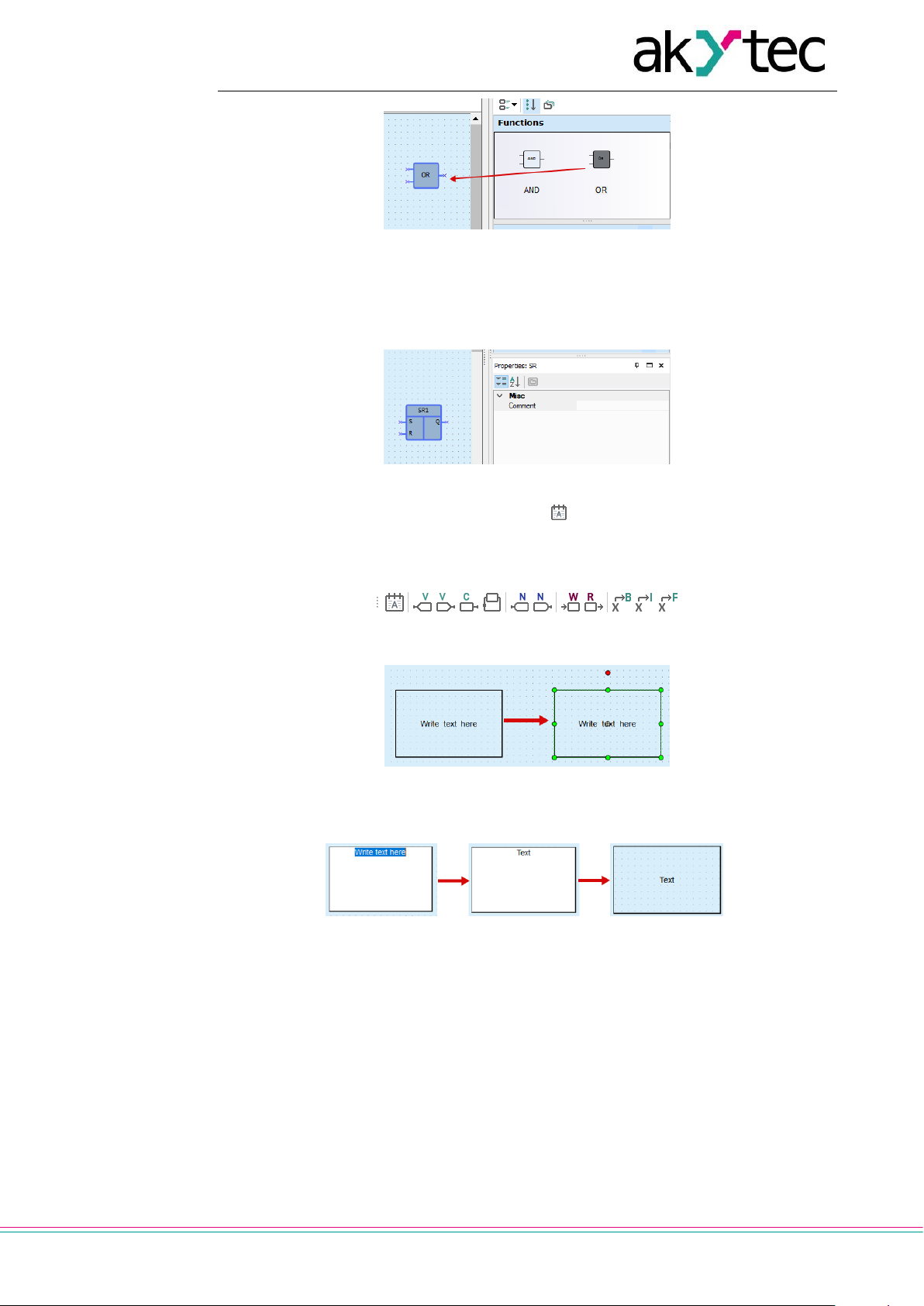
Circuit program development
akYtec GmbH · Vahrenwalder Str. 269 A · 30179 Hannover · Germany · Tel.: +49 (0) 511 16 59 672-0 · www.akytec.de
74
Fig. 7.3
7.2 Using of text field
Text fields are used to explain the program.
Fig. 7.4
To add a text field to the program, click the icon in the toolbar Insert (Table 2.6), then
choose the place for the text field in the workspace and use the left mouse button to draw
a rectangle.
Fig. 7.5
Fig. 7.6
Double-click the text field to write the text.
Fig. 7.7
The parameters of the text field can be changed in Property Box.
Page 76

Circuit program development
akYtec GmbH · Vahrenwalder Str. 269 A · 30179 Hannover · Germany · Tel.: +49 (0) 511 16 59 672-0 · www.akytec.de
75
Fig. 7.8
7.3 Using of variables
To add a variable to the program click the corresponding icon in the toolbar Insert (Table 2.6),
then click the workspace to place the variable block.
Fig. 7.9
Fig. 7.10
To reference a variable to the block use the icon in the row Variable in Property Box.
The variable table opens, but only the appropriate tabs in the table are visible. The selection of the displayed variables is determined by the type of the block.
Fig. 7.11
Select a variable or create a new one in the variable table (sect. 5) and confirm with OK.
Fig. 7.12
Use network variables to exchange data with other devices connected to the target device over network. For further details about using of network variables, refer to sect. 7.6.
If a variable block is highlighted in red, it means that the creation is incorrect or not completed.
Page 77
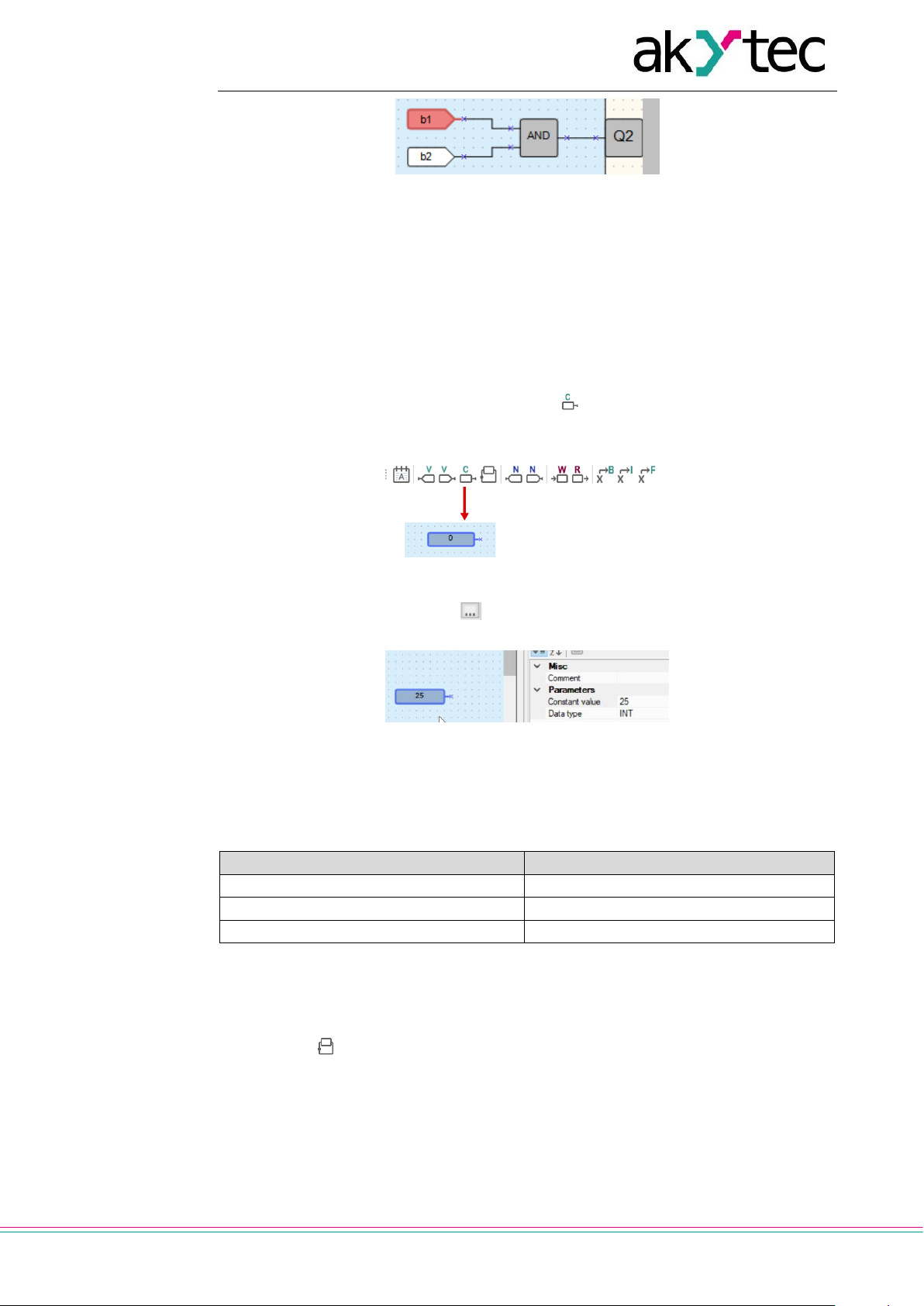
Circuit program development
akYtec GmbH · Vahrenwalder Str. 269 A · 30179 Hannover · Germany · Tel.: +49 (0) 511 16 59 672-0 · www.akytec.de
76
Fig. 7.13
The information about the error is displayed in the status bar.
It is recommended to start programming with the creation of variables in the variable ta-
ble.
If a variable is used more than once in a project, all references can be followed with the
item Show references in the variable block context menu. The function is also available
in simulation or online debugging modes.
7.4 Using of constants
To add a fixed value to the program click the icon in the toolbar Insert (Table 2.6),
then click the workspace to place the constant block.
Fig. 7.14
Select the data type using the icon in the row Data type and enter the value in the row
Constant value in Property Box.
Fig. 7.15
The value of the constant is not subject to change throughout the program execution.
It can be changed after double clicking on the constant block, in Property Box or by se-
lecting Change value in the block context menu.
Table 7.1 Data types valid values
Data type
Valid value
BOOL
0 / 1
INT
0…4,294,967,295
REAL
-3.402823e+38…3.402823e+38
7.5 Using of delay lines
A delay line is used to transfer the value from the block output to the block input, delayed
for one cycle. The output and input may belong to different blocks.
Click the icon in the toolbar Insert (Table 2.6) and draw a line from the output to the
input of a function or a function block. The delay line is displayed as a red dashed line
with an arrow.
Page 78

Circuit program development
akYtec GmbH · Vahrenwalder Str. 269 A · 30179 Hannover · Germany · Tel.: +49 (0) 511 16 59 672-0 · www.akytec.de
77
Fig. 7.16
Example:
A constant value 1 is transferred to the input I1 of the addition block ADD (Integer). A
value from the block output (Q) calculated in the previous cycle is transferred to the input
I1 over delay line.
Fig. 7.17
Table 7.2 Cycle signal values
Cycle
1 2 3 4 5 6 7 8 9
10
I2
0 0 1 1 2 2 3 3 4
4
Q
1 1 2 2 3 3 4 4 5
5
7.6 Network data exchange
The network input and output variables are special type of variables for data exchange
between devices connected to a common network.
The variables can be read via the network are called Network output variables ( ).
The variables can be written via the network are called Network input variables ( ).
To add a network variable to the program proceed as follows:
Click the icon or in the toolbar Insert (Table 2.6).
Click the workspace to insert the variable.
Click the icon in the row Variable in Property Box to select a variable for the
block.
Fig. 7.18
Select a variable or create a new one in the opened variable table and confirm
with OK. The selected variable is assigned to the variable block.
Page 79

Circuit program development
akYtec GmbH · Vahrenwalder Str. 269 A · 30179 Hannover · Germany · Tel.: +49 (0) 511 16 59 672-0 · www.akytec.de
78
Fig. 7.19
Connect the network variable output block to the desired block in the workspace.
Fig. 7.20
If the network output variable block is used for requesting a slave, it receives an addi-
tional parameter Write at the end of cycle. If the parameter is set to Yes, the new value
of the variable is assigned only at the end of the cycle, when all input variables are already read out.
Fig. 7.21
Note: A variable cannot be coupled with a block if there is no communication interfaces in
the device settings.
7.7 Read / write in FB
The block WriteToFB is used to change an FB parameter during the process.
Example:
The value of the parameter ON-duration of the FB BLINK1 should be 2 or 10 depending
on the value at the input I5.
To add the block WriteToFB to the program, click the icon in the toolbar Insert (Table
2.6), then click the desired place in the workspace.
Go to Property Box, select the FB BLINK1 in the row Function block and the parameter
of the FB in the row Parameter in FB (Fig. 7.22).
Page 80

Circuit program development
akYtec GmbH · Vahrenwalder Str. 269 A · 30179 Hannover · Germany · Tel.: +49 (0) 511 16 59 672-0 · www.akytec.de
79
Fig. 7.22
The block ReadFromFB is used to read the current value of an FB parameter and use it
in the program. The using is the same as of the WriteToFB block.
Fig. 7.23
7.8 Conversion blocks
Fig. 7.24
Conversion blocks are universal blocks used to convert an input value of any type into a
value of a certain type. There are three blocks available in the Insert toolbar (Table 2.6):
Table 7.3 Conversion blocks
Conversion to BOOL
Conversion of INT or REAL to BOOL
(If the input value > 0, the output = 1 / True)
Conversion to INT
Conversion of BOOL or REAL to INT
(REAL is rounded down to INT)
Conversion to REAL
Conversion of BOOL or INT to REAL
To add the conversion block to the program click one of the three icons in the toolbar In-
sert (Table 2.6), then click the desired place in the workspace.
Fig. 7.25
7.9 Arrange elements
The sequence numbers of the function blocks can be automatically re-assigned by clicking the button Arrange elements in the toolbar Service (Table 2.6). The blocks of the
same type are numbered sequentially from top to bottom and from left to right.
Page 81

Circuit program development
akYtec GmbH · Vahrenwalder Str. 269 A · 30179 Hannover · Germany · Tel.: +49 (0) 511 16 59 672-0 · www.akytec.de
80
Fig. 7.26
7.10 Execution sequence
Calculation of the values for outputs and delay lines is performed in a certain order. To
see this order click the arrow near the icon in the toolbar Service and select the De-
lay lines or Outputs (Table 2.6).
Fig. 7.27
To change the order, double-click an output or a delay line and enter the desired number.
Fig. 7.28
Click the icon to deactivate the edit mode.
7.11 Simulation
Use the simulation to proof the correctness of the created program. Only the offline simulation is currently possible. The simulation enables to analyze the values of all signals
within the circuit program. Change the values at the digital and analog inputs as well as
of variables and constants and check the values at the outputs.
7.11.1 Operation
To start / stop the simulation mode, click the icon Simulation mode in the toolbar
Service (Table 2.6). A new toolbar Simulation is displayed with the following controls:
Fig. 7.29
Page 82

Circuit program development
akYtec GmbH · Vahrenwalder Str. 269 A · 30179 Hannover · Germany · Tel.: +49 (0) 511 16 59 672-0 · www.akytec.de
81
Table 7.4 Simulation toolbar
Start
Start the permanent simulation
Single cycle
Step-by-step simulation. Click the icon to execute one program cycle.
Pause
Interrupt the simulation. Click the icon once more
to continue the simulation.
Stop
Stop simulation
Refresh time
Simulation refresh time in milliseconds
Cycle time
Cycle time
Time unit
Cycle time units: milliseconds, seconds, minutes,
hours
Watch Window
Open / close the window to watch the variables
values at each program step (sect. 7.11.2)
An additional toolbar Calendar is displayed in simulation mode if there are FBs of type
CLOCK or CLOCKW in the project (available only for devices with real-time clock).
Fig. 7.30 Calendar toolbar
The parameter Refresh time (ms) specifies the simulation cycle.
The parameter Cycle time specifies the program execution cycle during the simulation.
Note: The parameters Cycle time in device (sect. 3.2) and in ALP simulation mode are
different in spite of the same name.
Both parameters can be adjusted for faster or slower simulation of FBs CLOCK,
CLOCKW and BLINK.
The values of inputs, outputs and variables can be set by clicking on the block in the
workspace and entering a new value in the open dialog. The value of a network variable
can be set as well.
The digital inputs and outputs change their value and the color after each click.
Fig. 7.31
Fig. 7.32
Page 83

Circuit program development
akYtec GmbH · Vahrenwalder Str. 269 A · 30179 Hannover · Germany · Tel.: +49 (0) 511 16 59 672-0 · www.akytec.de
82
Fig. 7.33
If you want to make changes to the program, stop the simulation.
Notes:
Macros are excluded from simulation. Simulation for macros should be performed
separately in the workspace of the macro.
Simulation cannot be performed for
o blocks without connections with device outputs or a network variables
o incorrectly coupled variables
o retain variables
7.11.2 Watch Window
Click the icon on the simulation toolbar to track the input, output or variable values at
every program step.
Fig. 7.34 Watch Window
To add a variable, input or output to the Watch Window, click in the empty field in the
Name column and then click the icon appeared to the left. The context menu of these
blocks can also be used.
Fig. 7.35 Variable context menu in simulation
The values of the variables, inputs and outputs can be set in the Value column during
simulation.
7.12 Online debugging
To start the online debugging, click the icon in the toolbar.
In this mode the current values of all program variables, including functions, function
blocks, macros, inputs and outputs, are read out from the connected device and displayed in the workspace. This way you can check the logic of the device program.
Fig. 7.36
Page 84

Circuit program development
akYtec GmbH · Vahrenwalder Str. 269 A · 30179 Hannover · Germany · Tel.: +49 (0) 511 16 59 672-0 · www.akytec.de
83
The online debugging is possible only if:
the device is connected to the PC
the program in the device and the program opened in ALP is the same
the version of the device firmware is compatible with the current version of ALP
The online debugging is only available for the main program workspace, not within macros.
It is not possible to make changes in the project during online debugging. Exit online debugging by clicking the icon once more if you want to modify the project.
Note: If communication with the device is lost, online debugging is terminated after 10
seconds and the device is switched to operating mode. If the connection is restored within
10 seconds, online debugging continues, but the entered values are reset.
Manual value entry
It is possible to change the variable input value during online debugging by clicking on the
displayed value (Fig. 7.34). The new value should be entered in the field New value in
the opened window Prepared value. There are two options to change the value: one-off
or permanent change.
The one-off change enables to change the variable input value for one program cycle. In
the subsequent cycles, the signal from one of the device inputs or the output of another
program component connected to this input is used. The option is useful for single pulse
simulation.
When using the option Permanent change, the entered value is applied to the input until
the option is unchecked or the online debugging is stopped. The option is useful for simulation of time-constant signals.
Fig. 7.37
Note: Data exchange in online debugging mode is limited, and the limit depends on the
device model. A sign that the restriction is triggered are empty value cells in the diagram
during online debugging. In this case you should increase the scale of the workspace
(see 2.3) so that fewer values fall into the visible area. The entered values that do not fall
into the visible area remain saved, but do not occupy the memory area allocated for the
data exchange.
Page 85

Display programming
akYtec GmbH · Vahrenwalder Str. 269 A · 30179 Hannover · Germany · Tel.: +49 (0) 511 16 59 672-0 · www.akytec.de
84
8 Display programming
To determine the displayed information, use the tab Display Manager in the upper left
corner of the window. Display Manager (sect. 2.6) is only for target devices with display
available.
The display can be programmed using one or more display forms with “jumps” from one
to another so that the displayed information can be changed by program events (change
of variable) or by operator (button event).
Fig. 8.1
To open the selected form in Display Editor (sect. 8.1), use the command Edit display
form in the form context menu or double-click the form in the tree (Fig. 8.1).
Fig. 8.2 Display Editor
To open a graphical structure of display forms in Structure Editor (sect. 2.6, 8.2), use the
command Edit group in the group context menu (Fig. 8.1).
Fig. 8.3 Structure Editor
Page 86

Display programming
akYtec GmbH · Vahrenwalder Str. 269 A · 30179 Hannover · Germany · Tel.: +49 (0) 511 16 59 672-0 · www.akytec.de
85
8.1 Display Editor
A form may consist of several rows, at least two. The operator can switch between them
using the device function buttons. A display form is shown in the workspace with icons
on the right edge, which are used to change the number of the displayed rows. The rows
displayed first are outlined.
Fig. 8.4
Put the display elements from Library Box by drag-and-drop onto the form. For more information about display elements refer to sect. 6.4.
8.2 Graphical structure
To open a graphical structure of display forms in Structure Editor (sect. 2.6), use the command Edit group in the group context menu (Fig. 8.1).
By default, the graphical structure consists of one form. To add a display form to a group:
In Display Manager, use the group context menu or the toolbar icon (active if the
group is selected) (Fig. 8.1).
In Structure Editor, use the toolbar icon (Fig. 8.2).
To remove the form:
In Display Manager, use the item Delete in the form context menu (Fig. 8.1).
In Structure Editor, use the toolbar icon or the form context menu.
To change the position of a display form within a group in Display Manager, hold the Shift
key while you drag-and-drop the form.
If the display structure consists of more than one form, “jumps” should be defined to ena-
ble the navigation between forms (sect. 8.3, Fig 8.2).
To use copy / paste operations for display forms see sect. 8.4.
8.3 Form properties / Jumps
Select a form in the structure to see its properties:
Name
Description
Jump parameters
Each new display form has a default name that can be changed here. The description is
optional.
Page 87

Display programming
akYtec GmbH · Vahrenwalder Str. 269 A · 30179 Hannover · Germany · Tel.: +49 (0) 511 16 59 672-0 · www.akytec.de
86
Fig. 8.5
To program the navigation through the display forms using different events, click the
icon in the row to display form. In the opened dialog Jump in the section to display
form, select the form to which the display should switch if in the Jump condition section
specified event occurs.
Select the event in the section Jump condition, as a device event or change of a variable by value.
Fig. 8.6
A button event can be selected as Device event.
A BOOL variable can be selected for Change by value event.
Fig. 8.7 Device events
Fig. 8.8 Program events
Confirm with OK. The created jump is shown in the structure.
Page 88

Display programming
akYtec GmbH · Vahrenwalder Str. 269 A · 30179 Hannover · Germany · Tel.: +49 (0) 511 16 59 672-0 · www.akytec.de
87
Fig. 8.9 Jump graphical representation
The jump between two forms can occur by several events and the graphical structure can
reach a very high complexity.
8.4 Copy / paste display form
A display form or a group of forms can be copied and pasted into the same or another
project. To copy a display form or a group of forms, use the item Copy in the form context
menu and Copy group in the group context menu, as well as the shortcut Ctrl + C. The
keys Ctrl and Shift can also be used to select several forms.
Fig. 8.10
Use the item Paste in the form or group context menu or the shortcut Ctrl + V to insert
the form into the group. The variables associated with the form are copied with, according
to the rules described in sect. 5.6 “Copy / paste variables”. Jumps between the selected
forms are copied with. If only one of the forms connected by the jump is selected, the
jump will be deleted during the insertion.
Page 89

Keyboard shortcuts
akYtec GmbH · Vahrenwalder Str. 269 A · 30179 Hannover · Germany · Tel.: +49 (0) 511 16 59 672-0 · www.akytec.de
88
9 Keyboard shortcuts
Shortcut
Description
Use
Ctrl + N
New project
Menu / File
Ctrl + O
Open project
Menu / File
Ctrl + Alt + S
Save project as…
Menu / File
Ctrl + S
Save project
Menu / File
Ctrl + Р
Print…
Menu / File
Ctrl + Z
Undo
Menu / View
Ctrl + Y
Redo
Menu / View
Ctrl + F7
Transfer application to device
Menu / Device
F1
Help
Menu / Help
Ctrl + С
Copy
Work with elements
Ctrl + V
Paste
Work with elements
DEL
Delete
Work with elements
Ctrl + →
Increase the element width
Resize element
Ctrl + ←
Decrease the element width
Resize element
Ctrl + ↑
Increase the element height
Resize element
Ctrl + ↓
Decrease the element height
Resize element
Ctrl + wheel up
Zoom+
Resize workspace image
Ctrl + wheel down
Zoom-
Resize workspace image
Page 90

Program examples
akYtec GmbH · Vahrenwalder Str. 269 A · 30179 Hannover · Germany · Tel.: +49 (0) 511 16 59 672-0 · www.akytec.de
89
10 Program examples
Two examples with simple tasks explain the creation of a circuit program in the ALP programming software.
10.1 Task 1: Light switch with automatic switch-off
The task is to switch the light on for a certain time, e.g. for a house entry.
Task definition:
1. The light sensor F1 and the light button SB1 “TIME” are installed in front of the en-
trance door.
2. If the button SB1 is shortly pressed and the ambient light is insufficient, the light
should be switched on for 1 minute – this time should be enough to find a key hole
and to open the door.
3. If the button SB1 is pressed for 2 seconds, the light should be switched on for 3
minutes regardless of the ambient light – this mode can be useful for entrance cleaning.
4. Provide the possibility to control the light by commands from external devices or with
the switch SA1 “CONST” regardless of the ambient light. This mode can be useful
during the reception of guests or for further automation of the apartment as part of the
"smart house" program.
5. Provide the possibility to switch on the light only at a certain time.
Device selection:
The control device must have minimum two digital inputs, one digital output and an integrated real-time clock to implement this task. These features can be provided by devices
of PR110 series with the letters "RTC" in the designation.
The task implementation with the device PR110-24.8D.4R-RTC:
Fig. 10.1
Circuit program
The circuit program can be implemented in the way shown in Fig. 10.2.
Page 91

Program examples
akYtec GmbH · Vahrenwalder Str. 269 A · 30179 Hannover · Germany · Tel.: +49 (0) 511 16 59 672-0 · www.akytec.de
90
Fig. 10.2
Input I1 – connected to the light sensor F1
Input I2 – connected to the button SB1
Input I3 – connected to the switch SA1
Output Q1 – output to implement the task points 1-4
Output Q2 – output to implement the task point 5
Program description:
1. If the button SB1 is shortly pressed (< 2 s), the logical AND (D2) is enabled. If the
ambient light is insufficient, the first input of D2 is also True and the timer TP “Pulse”
(D3) forms a pulse with 1 minute duration. This pulse activates the output Q1 over the
logical OR (D6) and the light is switched on for 1 minute.
2. If the button SB1 is pressed for > 2 s, the on-delay timer TON (D4) activates the timer
TP “Pulse” (D5), a pulse with the duration of 3 minutes activates the output Q1 over
logical OR (D6) and the light is switched on for 3 minutes.
3. If the ambient light is sufficient, the contact of the sensor F1 is closed, the logical
AND (D2) is disabled and the timer TP “Pulse” (D3) is blocked.
4. If the switch SA1 “CONST” is closed, the output Q1 is activated over the logical OR
(D6) and the light is switched on constantly.
5. If you want to use the light only on certain weekdays at certain times, you can use the
output Q2. With the weekly timer CLOCKW (D7) you can set the start and the stop
time and the weekdays for lighting.
The circuit program created in ALP is shown in Fig. 10.3.
Page 92

Program examples
akYtec GmbH · Vahrenwalder Str. 269 A · 30179 Hannover · Germany · Tel.: +49 (0) 511 16 59 672-0 · www.akytec.de
91
Fig. 10.3
10.2 Task 2: Mixer control
The task is to implement an industrial mixer with simple control functions.
Task definition:
1. Automatic and Manual operation modes are required. The switch SA1 “MODE” is in-
stalled to switch between the modes.
2. In Automatic mode the operating cycle can be started with the button SB1 “START”
and stopped automatically with the end of the cycle or manually with the button SB2
“STOP”. The cycle duration is 5 minutes. During the cycle the motor of the mixer is on
for 15 seconds and off for 10 seconds alternately. All settings can be changed in the
program.
3. In Manual mode the motor can be started with the button SB1 “START” and stopped
with the button SB2 “STOP”.
4. When the motor is overloaded (overload switch F1), it should be switched off auto-
matically, an intermittent acoustic warning signal (HA1) with the 3-second interval
should be produced and an operating error should be indicated by the signal lamp
HL1 "Overload".
5. The acoustic signal can be switched off with the button SB3 “RESET”.
6. The button SB4 “CONTROL” is used for the functional test of the lamp HL1 and the
acoustic signal HA1.
Device selection:
The control device must have minimum 6 digital inputs and 3 digital outputs to implement
this task. These features can be provided by devices of PR110 series.
The task implementation with the device PR110-24.8D.4R:
Page 93

Program examples
akYtec GmbH · Vahrenwalder Str. 269 A · 30179 Hannover · Germany · Tel.: +49 (0) 511 16 59 672-0 · www.akytec.de
92
Fig. 10.4
Circuit program
The circuit program can be implemented in the way shown in Fig. 10.5.
Fig. 10.5
Input I1 – connected to the switch SA1 “MODE”
Input I2 – connected to the button SB1 “START”
Input I3 – connected to the button SB2 “STOP”
Input I6 – connected to the overload switch F1
Input I7 – connected to the button SB3 “RESET”
Input I8 – connected to the button SB4 “TEST”
Output Q1 – connected to the motor
Output Q2 – connected to the acoustic signal HA1
Output Q3 – connected to the signal lamp HL1
Program description:
1. Input I2 (SB1 “START”)
Page 94

Program examples
akYtec GmbH · Vahrenwalder Str. 269 A · 30179 Hannover · Germany · Tel.: +49 (0) 511 16 59 672-0 · www.akytec.de
93
If the button SB1 is pressed, the RS trigger D1 becomes True as long as there is no reset
signal at the input R. Subsequent signal path depends on the state of the switch SA1
“MODE”:
If SA1 is open (Manual mode), the logical AND (D7) and the logical OR (D8) are ena-
bled and the motor M1 (output Q1) is switched on.
If SA1 is closed (Automatic mode), the logical AND (D7) is disabled and the start sig-
nal can only activate the pulse generator BLINK (D5) to start the operating cycle (15 s
on / 10 s off) and the on-delay timer TON (D4) to stop it (in 5 min).
2. Input I3 (SB2 “STOP”)
If the button SB2 is pressed or the switch F1 is activated, the RS trigger D1 is reset
over the input R and the output Q1 is disabled.
3. Input I1 (SA1 “MODE”)
If the switch SA1 is open (Manual mode), the logical AND D3 is disabled and D7 is
enabled, the timer D4 and the pulse generator D5 are disabled and the motor M1 can
be only started with SB1 and stopped with SB2.
If the switch SA1 is closed (Automatic mode), the logical AND D3 is enabled and D7
is disabled, thus the motor M1 can be only started by the pulse generator D5 (15 s on
/ 10 s off cycle) and stopped by the timer D4 in 5 minutes.
4. Input I6 (overload switch F1)
When the motor is overloaded, the F1 contact is closed, the RS trigger D1 is reset
and the motor is stopped.
Concurrently the signal lamp HL1 is switched on over the logical OR (D12) and the
acoustic signal HA1 is activated over the RS trigger D9. The pulse generator D10
provides an intermittent acoustic signal with the cycle 3 s on / 3 s off.
5. Input I7 (SB3 “RESET”)
The button RESET is used to reset the acoustic signal HA1. If the button SB3 is
pressed, the RS trigger D9 is reset and the pulse generator D10 for the acoustic signal HA1 is stopped.
6. Input I8 (SB4 “TEST”)
The button TEST is used to test the acoustic signal HA1 and the signal lamp HL1. If
the button SB4 is pressed, the logical ORs D11 and D12 are enabled, the outputs Q2
and Q3 activated, the acoustic signal and the lamp are switched on.
The circuit program is shown in Fig. 10.6.
Page 95

Program examples
akYtec GmbH · Vahrenwalder Str. 269 A · 30179 Hannover · Germany · Tel.: +49 (0) 511 16 59 672-0 · www.akytec.de
94
Fig. 10.6
Notes:
1. The remaining two unused inputs and one output can be used for implementation of
additional functions. For example, to switch between different time settings for automatic motor operation or to switch other operating parameters of the mixer.
2. The technological cycle of operation can be completely automated by implementation
of an incremental counter (CT) to switch off the RS trigger D1.
 Loading...