

Page 1

USER’S GUIDE
Installation & Operation
Instructions
Electromagnetic Flow Meter
Page 2

AFLO-Electromagnetic Flow Meter
1
Page 3

AFLO-Electromagnetic Flow Meter
INDEX
1.Introduction…………………………………………………………………………………………….3
1.1. Sensor……………………………………………………………………………………………………………………....3
1.2. Transmitter………………………………………………………………………………………………………………..4
2. Technical Specifications………………………………………………………………………….4
3. Technical Drawings ……………………………………………………………………………… 5
4. Wiring ……………………………………………………………………………………………………7
4.1. Compact type Terminal …………………………………………………………………………………………….……7
4.2. Remote type Terminal ……………………………………………………………………………………………………9
5. Digital outputs……………………………………………………………………………………..12
6. Operating…………………………………………………………………………………………….13
6.1.Compact Transmitter Display …………………………………………………………………………………….…13
6.2.Remote Transmitter Display ……………………………………………………………….…………………..……13
6.3. Keys Functions…………………………………………………………………………………………………….….….14
6.4. Functions select menu………………………………………………………………………………………….……..14
6.5. Parameters Configuration ………………………………………………………………………………………..….14
6.5.1.Passwords………………………………………………………………………………………………….…….…16
6.5.2. Details Parameters ……………………………………………………………………………………………16
6.6. Alarm information ……………………………………………………………………………………………………….21
7. Troubleshooting .………………………………………………….……………………………..21
7.1. No display…………………………………………………………………………………………………………………...21
7.2. Exciting alarm ……………………………………………………………………………………………………………..21
7.3.Empty pipe alarm………………………………………………………………………………………………………….22
8. MOUNTING CONDITIONS.......................................................................22
9. SHIPPING AND STORAGE CONDITIONS…………………………………………………23
2
Page 4
AFLO-Electromagnetic Flow Meter
1. Introduction
AFLO electromagnetic flowmeters offer reliable, precise and inexpensive flow measurement on all
electrically conductive liquids. Typical applications are found in all industries. E.g.:
Water sector: Potable water, treatment of chemicals, waste water and sludge.
Food sector: Dairy products, beer, wine, soft-drinks and fruit juices.
Chemical sector: Detergents, pharmaceuticals, acids and alkalies.
Other sectors: District heating, paper pulp and mining slurries.
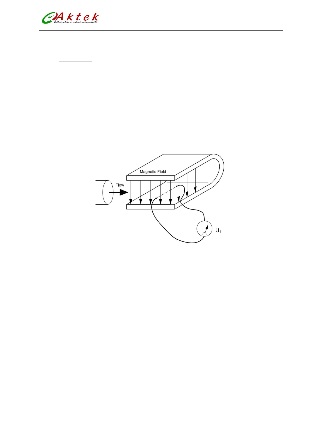
The flow measuring principle is based on Faraday’s law of electromagnetic induction.
Figure (1)
Ui = When an electrical conductor of length L is moved at velocity v, perpendicular to the lines of
flux through a magnetic field of strength B, the voltage Ui is induced at the ends of the conductor
Ui = L x B x v
Ui = Induced voltage
L = Conductor length = Inner pipe diameter = k1
B = Magnetic field strength = k2
v = Velocity of conductor (media)
k = k1 x k2
Ui = k x v, the electrode signal is directly proportional to the fluid velocity
1.1.SENSOR
The sensor converts the flow into an electrical voltage (Ui) proportional to the velocity of the flow.
The sensor is built up of a stainless steel pipe, 2 coils, electrodes, an isolating liner, housing and
where applicable, connecting flanges.
3
Page 5
AFLO-Electromagnetic Flow Meter
Fluid conductivity
≥ 5 μS / cm
Accuracy
±0.5%
Keypad
4 control buttons
Ambient Temperature
-20…+60 ˚C
Output
0-10 mA, 4-20 mA, Frequency, Pulse
Communication
RS485 MODBUS
Display
3 Lines LCD
Power Supply
85…250 VAC 45…63Hz 20W,
20…36 VDC or battery powered
Protection
IP67
Totalizer
Forward, reverse and net totalizer
Nominal Size mm
DN10…DN3000
Nominal Pressure
PN6,10,16,25,40
Liner
Neoprene, PTFE, FEP, Hard Rubber, Polyurethane
Electrodes
AISI 316L St. St., Hastelloy, Titanium, Tantalum, Platinum-Iridium
Operating temperature
-20...+80 °C (hard rubber) -20...+120 °C (with Teflon and away from the
transmitter installation)
Measuring Tube
Stainless steel
Body Material
Carbon Steel
Protection
IP 67 / IP 68 (for remote version)
1.2.TRANSMITTER
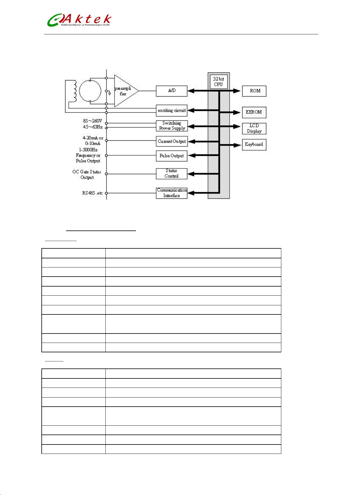
The transmitter consists of a number of function blocks which convert the sensor voltage into flow
readings.
Figure (2)
2. Technical Specifications
Transmitter
Sensor
4
Page 6
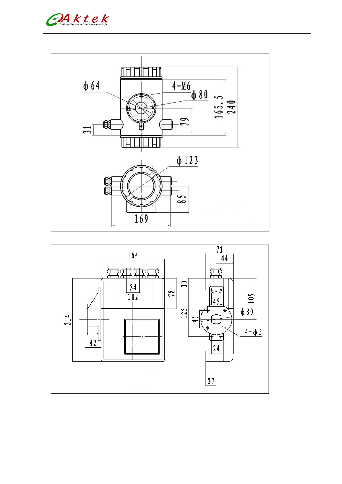
3. Technical Drawings
AFLO-Electromagnetic Flow Meter
Figure (3)
Figure (4)
5
Page 7
AFLO-Electromagnetic Flow Meter
DN
Dimensions(Pressure 1.6MPa)
Dimensions(Pressure 4.0MPa)
L
H
Weight
Kg
D
d1
d0 n b D d1
d0 n b
15
95
65
14 4 16
95
65
14 4 16
200
160
13
20
105
75
14 4 18
105
75
14 4 18
200
167
13
25
115
85
14 4 18
115
85
14 4 18
200
169
13
32
140
100
18 4 18
140
100
18 4 18
200
185
13
40
150
110
18 4 20
150
110
18 4 20
200
193
15
50
165
125
18 4 20
165
125
18 4 20
200
206
16
65
185
145
18 4 20
185
145
18 4 22
250
224
20
80
200
160
18 8 22
200
160
18 8 22
250
241
22
100
220
180
18 8 22
235
190
22 8 26
250
263
25
125
250
210
18 8 22
270
220
26 8 26
250
295
33
150
285
240
22 8 24
300
250
26 8 28
300
325
36
DN
Pressure 1.6 Mpa
Pressure 1.0MPa
200
340
295
22
12
26
340
295
22 8 24
350
383
46
250
405
355
26
12
28
395
350
22
12
26
450
440
65
300
460
410
26
12
32
445
400
22
12
28
500
498
75
350
520
470
26
16
35
505
460
22
16
30
500
553
100
400
580
525
30
16
38
565
515
26
16
32
500
608
160
450
640
585
30
20
42
615
565
26
20
35
550
665
170
500
715
650
33
20
46
670
620
26
20
38
550
727
210
600
840
770
36
20
52
780
725
30
20
42
600
840
240
DN
Pressure 1.0 MPa
Pressure 0.6MPa
700
895
840
30
24
30
860
810
26
24
26
700
895
270
800
1015
950
33
24
32
975
920
30
24
26
800
1002
900
1115
1050
33
28
34
1075
1020
30
24
26
900
1107
1000
1230
1160
36
28
34
1175
1120
30
28
26
1000
1222
1200 1405
1340
33
32
28
1200
1437
1400 1630
1560
36
36
32
1400
1663
1600 1830
1760
36
40
34
1600
1863
1800 2045
1970
39
44
36
1800
2072
2000 2265
2180
42
48
38
2000
2282
2200 2475
2390
42
52
42
2200
2487
2400 2685
2600
42
56
44
2400
2636
2600 2905
2810
48
60
46
2600
2836
2800 3115
3020
48
64
48
2800
3036
3000 3315
3220
48
68
50
3000
3236
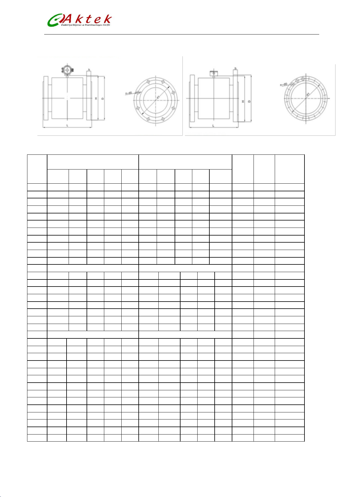
Dimensions according to Nominal Pressure Value for Remote and Compact Type
Figure (5)
6
Page 8
4. Wiring
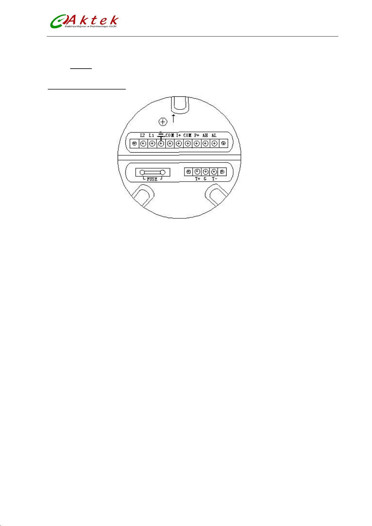
4.1.Compact type Terminal
AFLO-Electromagnetic Flow Meter
Figure (6)
I+: Output Current for Flow Measurement G: RS232 Communication Ground
COM: Output Current (Ground) for Flow Measurement L1:220V(24V)Power Supply
P+: Frequency(Pulse) Output for Bi-directional Flow L2:220V(24V)Power Supply
COM: Frequency (Pulse) Output (Ground)
AL: Alarm Output for Low Limit
AH: Alarm Output for Upper Limit
COM: Alarm Output (Ground)
FUSE: Fuse for Power Supply
T+: +Communication Input Signal(RS485-A)
T-: -Communication Input Signal(RS485-B)
7
Page 9
AFLO-Electromagnetic Flow Meter
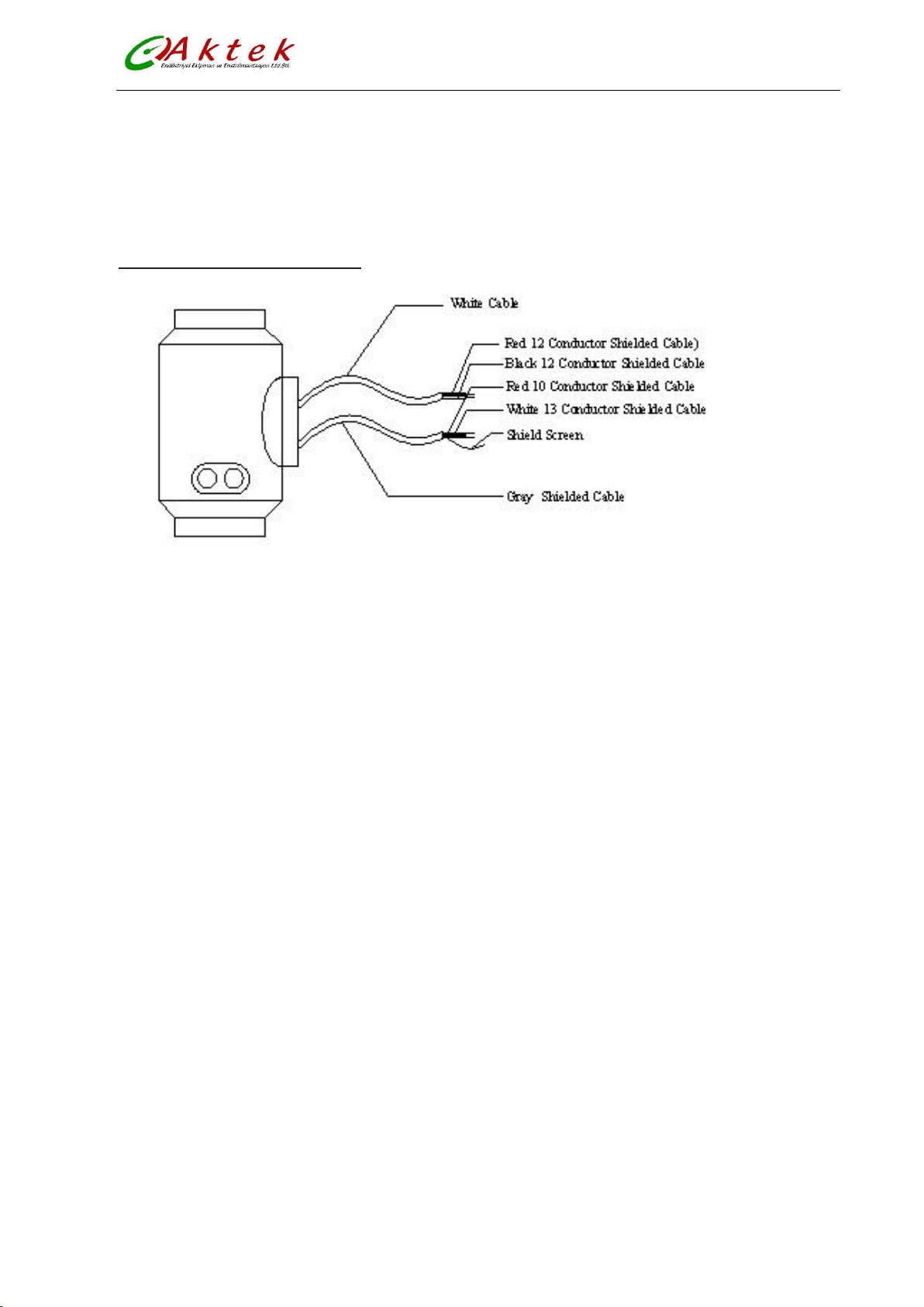
Signal lines labels in compact type
White twisted-pair cable (for exciting current)
12 Conductors (Red)
12 Conductors (Black)
Grey shielded twisted-pair cable
10 Conductors (Red) connected to “Signals 1”
13 Conductors (White) connected to “Signals 2”
Shielded Conductor connected to “Signal Ground”
Figure (7)
8
Page 10
AFLO-Electromagnetic Flow Meter
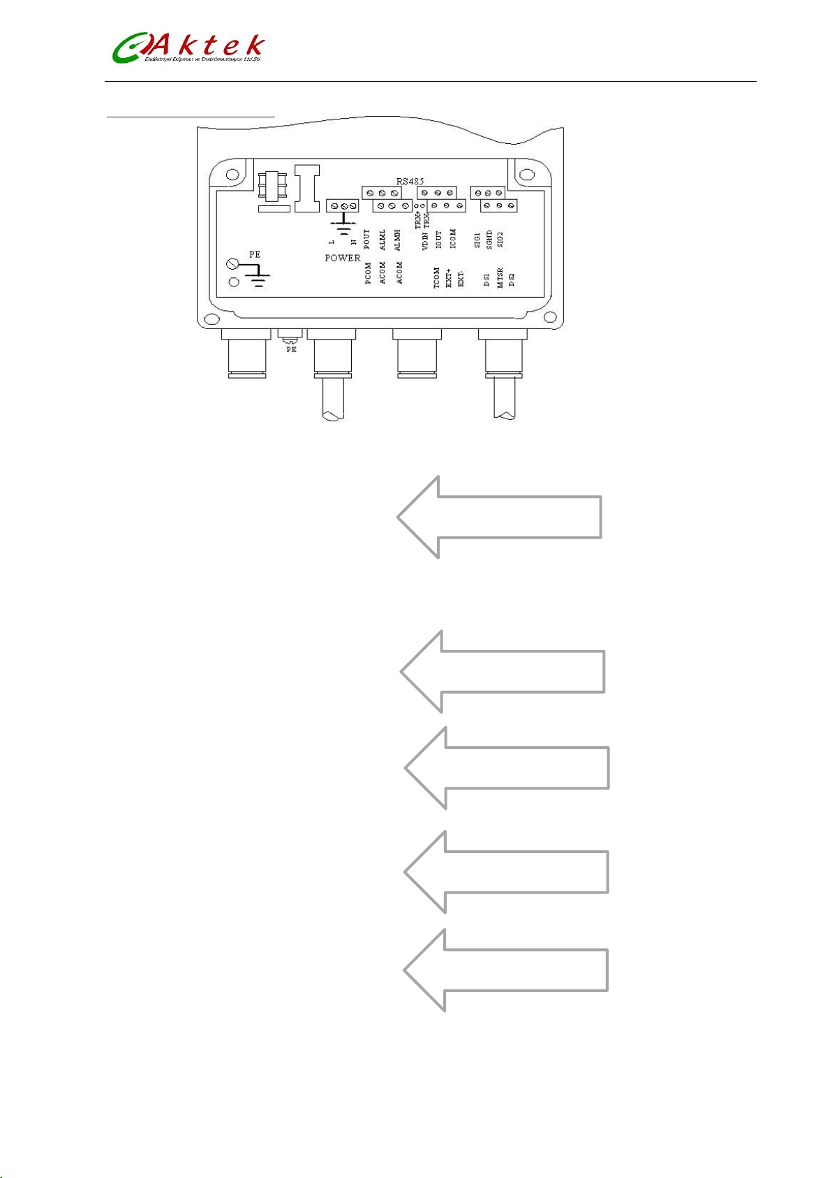
To Separate Model Sensor
Analog Current Output
Frequency (Pulse) Output
Communication Input
Two Alarm Outputs
4.2.Remote type Terminal
Figure (8)
SIG 1 Signal 1
SGND Signal Ground
SIG 2 Signal 2
DS1 Shielded Exciting 1
DS2 Shielded Exciting 2
EXT+ Exciting Current+
EXT- Exciting Current-
VDIN Current two lines 24V Spots
ICOUT Analog Current Output
ICCOM Analog Current Output Ground
POUT Flow Frequency (Pulse) Output
PCOM Frequency (Pulse) Output Ground
ALMH Upper Limit Alarm Output
ALML Low Limit Alarm Output
ALCOM Alarm Output Ground
TRX+ Communication Input (RS485-A)
TRX- Communication Input (RS485-B)
TCOM 232 Communication Ground
9
Page 11
AFLO-Electromagnetic Flow Meter
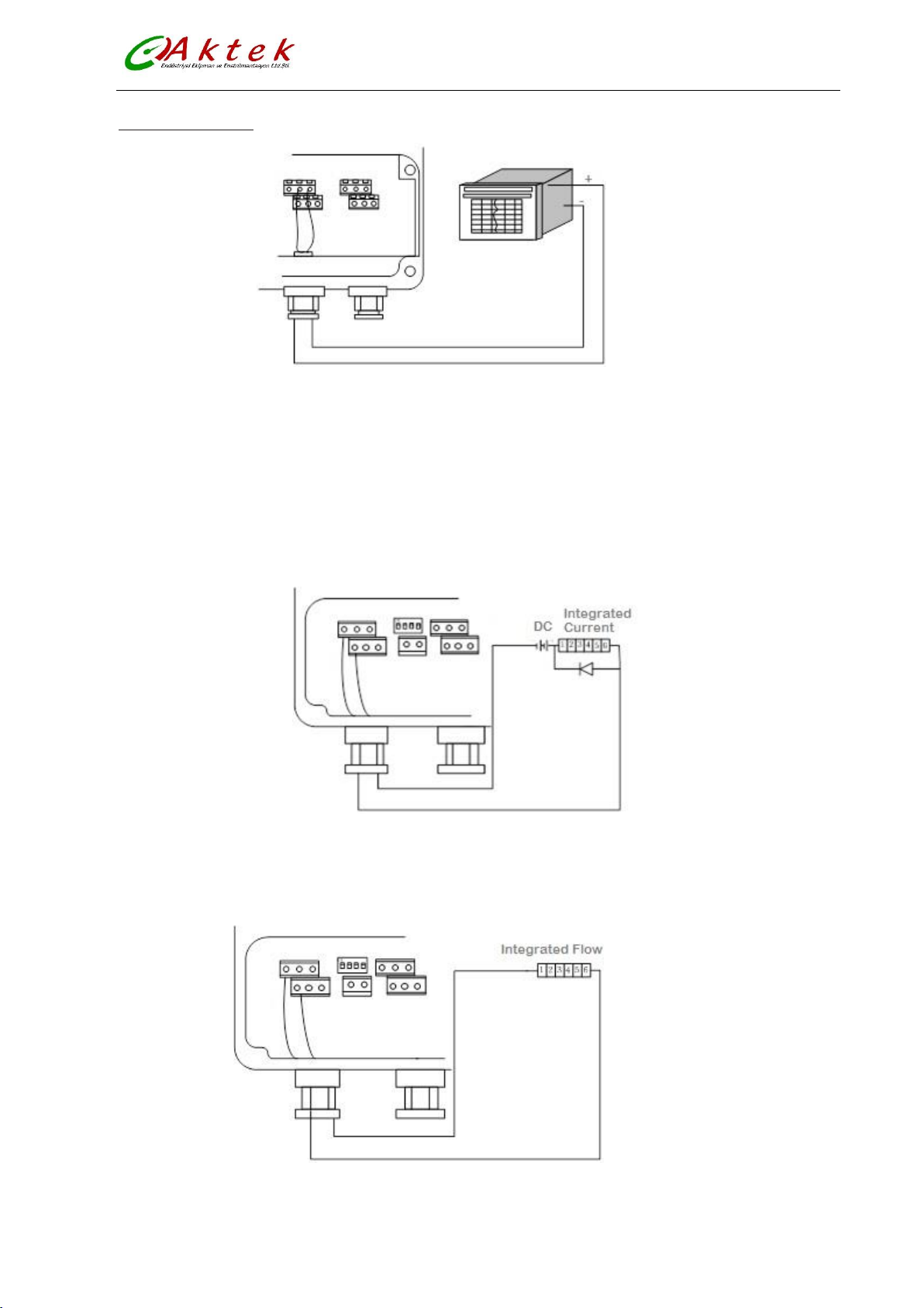
Output connection
I out I com
Figure (9) output current circuit
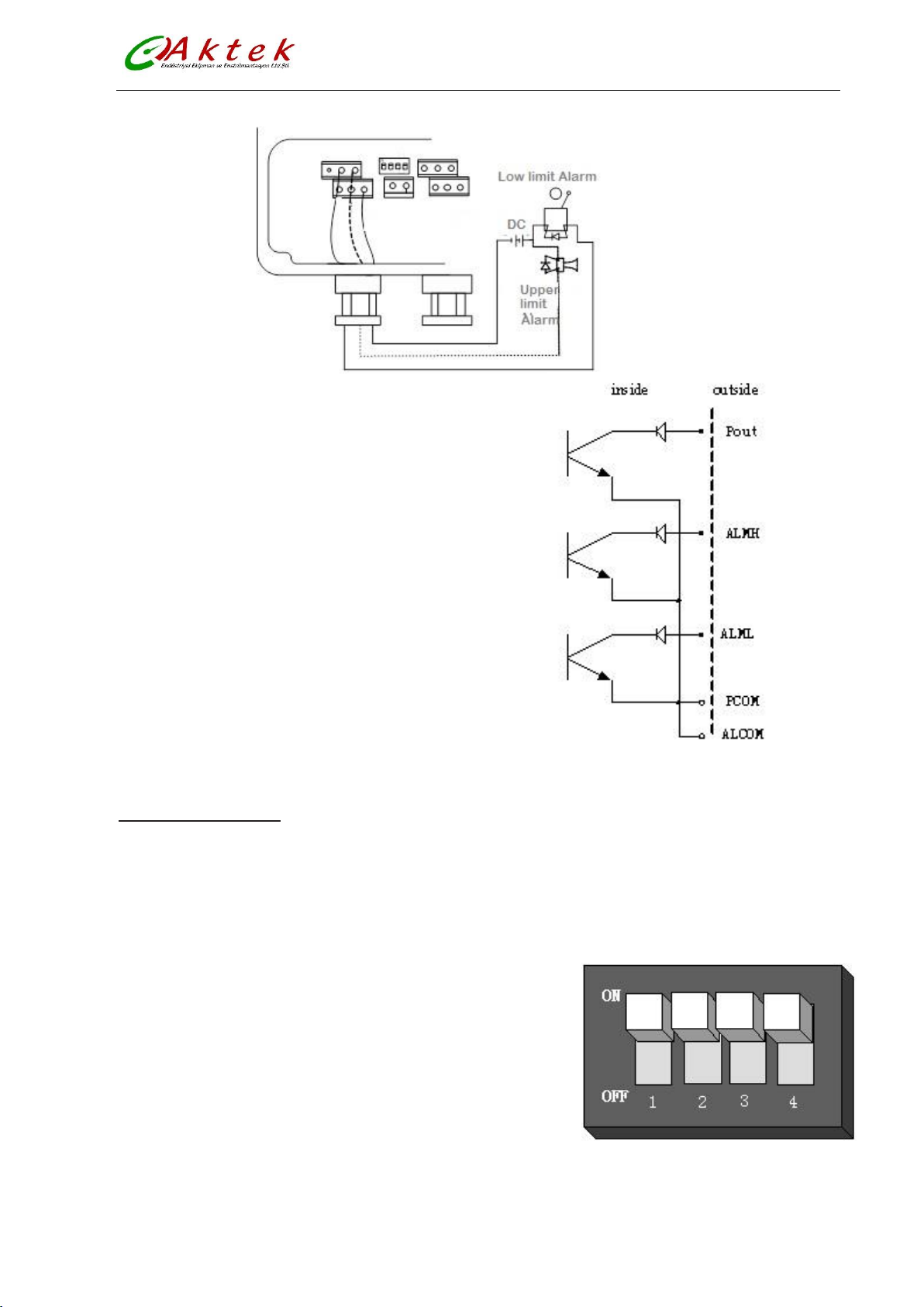
When DIP switch set to ON, AFLO Transmitter can provide +28V as a power supply and up-pull 10kΩ
resistance to output Frequencies (PUL) to isolated OC gate, Alarm Output (ALMH.ALML), and Status Control
(INSW). Frequency output obtained from POUT and PCOM terminals when DIP switch set as ON
When inductive load is connected to converter, a diode should be used as shown in figure (10)
Figure (10) Connection of electro magnet counter
Electronic counter connection as shown in figure (11)
Figure (11)
10
Page 12
AFLO-Electromagnetic Flow Meter
Alarm output connection as shown in figure (12)
Figure (12)
OC gate connection as shown in figure (14)
Figure (14)
ON/OFF Switch Diagram
Key 1 ON: Supply up power (24V) for ALML output.
OFF: No connection.
Key 2 ON: Pulse output to OC gate when flow verification was taken. Connect pull -up resistor.
OFF: No connection.
Key 3 ON: Supply up power (24V) for ALMH output.
OFF: No connection.
Key 4 ON: Connected to RS485 terminal resistor for communication
OFF: No connection.
Note Terminal used for far communication only.
Figure (15)
11
Page 13
AFLO-Electromagnetic Flow Meter
5. Digital outputs
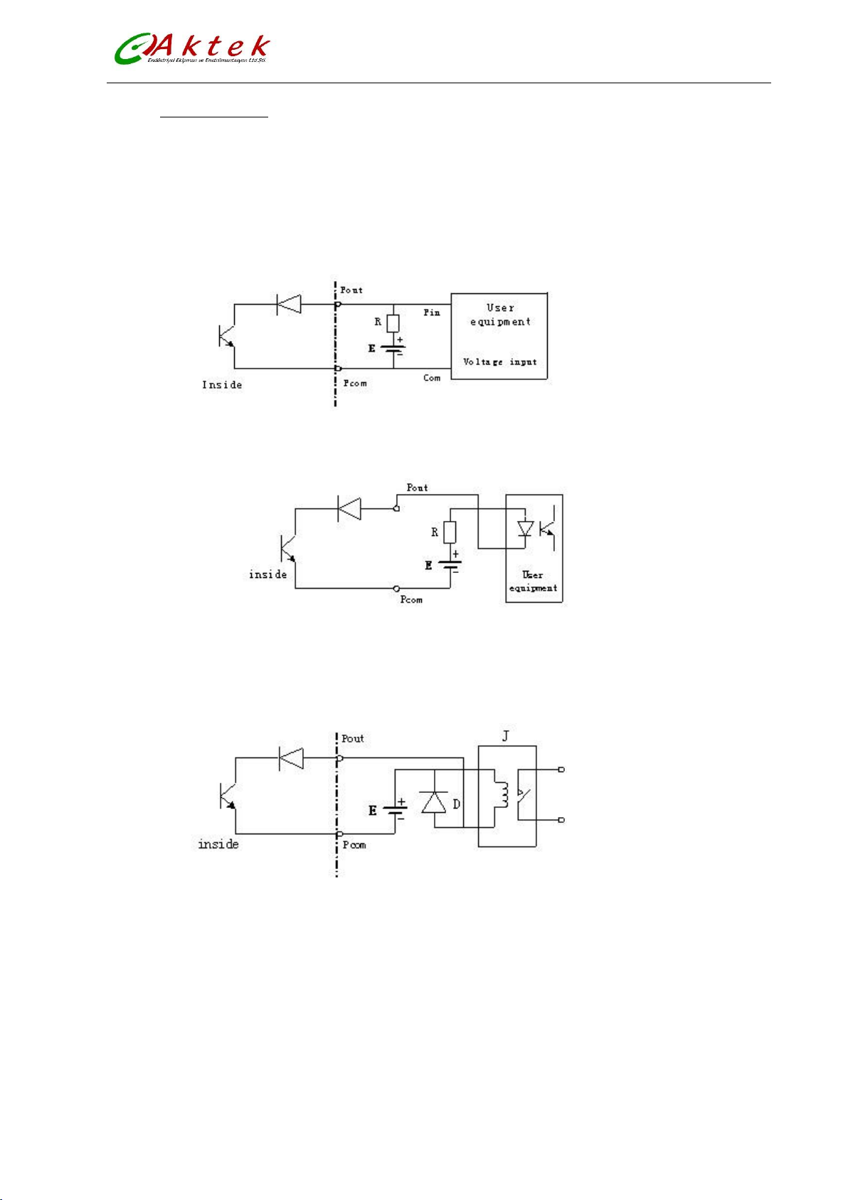
Digital output means frequency output and pulse output, and both of them use the same output point, so
user can choose only one type of them not both
Digital voltage output connection as shown in figure (15)
Figure (15)
Photoelectricity coupling (PLC etc.) connection as shown in figure (16)
Figure (16)
Relay connection as shown in figure (17), mostly relays has a diode inside. If not, user should connect one
externally.
Figure (17)
12
Page 14
AFLO-Electromagnetic Flow Meter
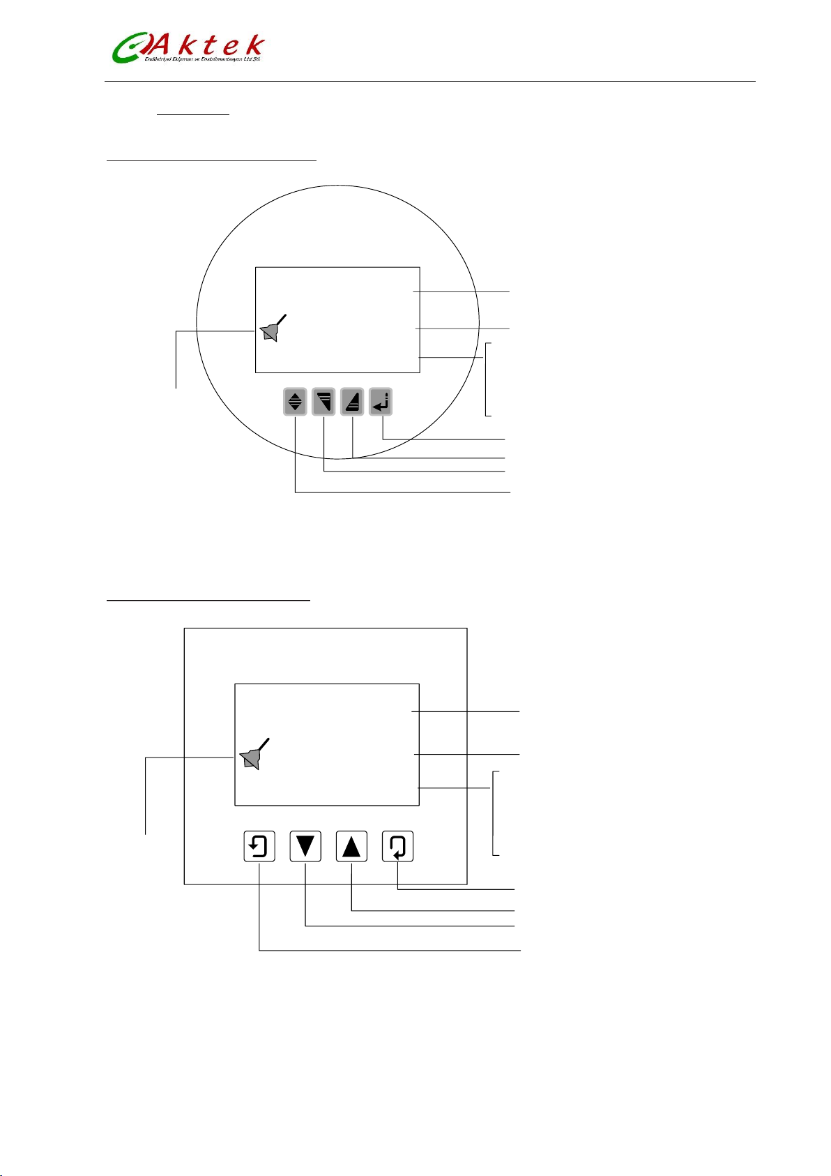
Flow volume
Unit
Flow velocity
(FLS)
Percentage
(
FQP
)
Ratio of emptiness
(MTP)
Forward and reverse intergated volumes
Deference of forward and reverse
Alarm
Enter
Down ; minusl 1, page down
Up
; plus 1, page up
Compound
Alarm
indicator
+ 282.92
FQH m
3
/ h
+ 00000013
.
5 m
3
×1
∑
Flow volume
Unit
Flow velocity
(FLS)
Percentage
(
FQP
)
Ratio of emptiness
(MTP)
Forward and reverse intergated volumes
Deference of forward and reverse
Alarm
Enter
Down ; minusl 1, page down
Up
; plus 1, page up
Compound
Alarm
indicator
+ 282.92
FQH m3/ h
+ 00000013.5 m
3
×1
∑
6. Operating
6.1.Compact Transmitter Display
6.2.Remote Transmitter Display
Figure (18)
Figure (19)
13
Page 15
AFLO-Electromagnetic Flow Meter
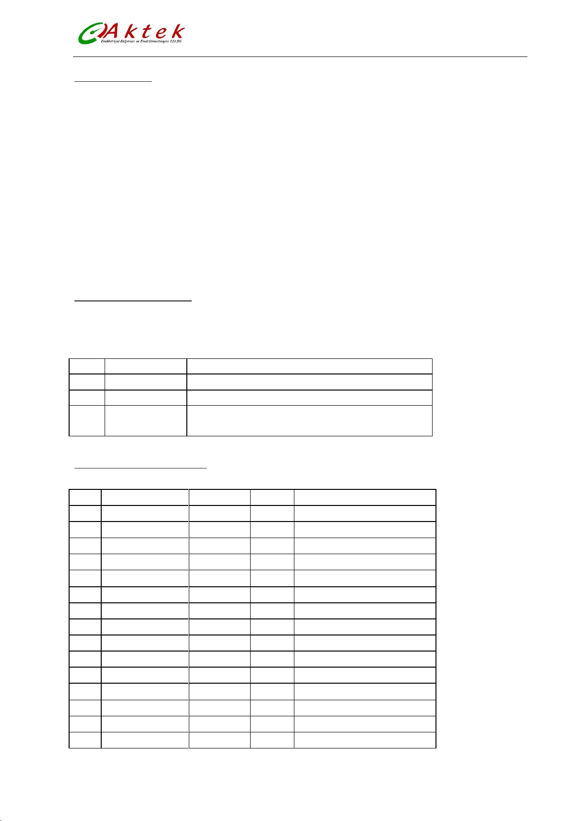
Code
Functions
Notes
1
Parameters Set
Enter a password , and then adjust parameters settings.
2
Clr Total Rec
reset totalizer
3
Fact Modif Rec
Select this function, it can be check the factor‘s modify
Record
Code
Parameter words
Setting Way
Grades
Range
1
Language
Select
2
English
2
Comm Addres
Set count
2
0~99
3
Baud Rate
Select
2
300~38400
4
Snsr Size
Select
2
3~3000
5
Flow Unit
Select
2
L/h, L/m, L/s, m3/h, m3/m, m3/s
6
Flow Range
Set count
2
0~99999
7
Flow Rspns
Select
2
1~50
8
Flow Direct
Select
2
Plus/ Reverse
9
Flow Zero
Set count
2
0~±9999
10
Flow Cutoff
Set count
2
0~599.99%
11
Cutoff Ena
Select
2
Enable/Disable
12
Total Unit
Select
2
0.001m3~1m3 、 0.001L~1L
13
SegmaN Ena
Select
2
Enable/Disable
14
Analog Type
Select
2
0~10mA /4~20mA
15
Pulse Type
Select
2
Freque / Pulse
6.3.Keys function
“Down” key: Selecting displayed data on lower line in turn
“Up” key: Selecting displayed data on higher line in turn
“Compound” key + “Enter” key: Come into parameter setting
“Enter” key: Press it to come into selected function
Adjust LCD contract using “Compound” key + “Up” key or “Compound” key + “Down” key for several
seconds
“Compound” key + “Down” key: Cursor turns left
“Compound” key + “Up” key: Cursor turns right
“Enter” key: Press for two seconds under any state and will return to measuring, after 3 minutes It will
return to the measuring automatically
6.4.Functions select menu
Push “Compound ”+“Enter” keys for functions select, push “Up” or “Down” keys to select one of the
following parameters.
6.5.Parameters Configuration
14
Page 16
AFLO-Electromagnetic Flow Meter
16
Pulse Fact
Select
2
0.001m3~1m3 , 0.001L~1L
17
Freque Max
Select
2
1~ 5999 HZ
18
Mtsnsr Ena
Select
2
Enable/Disable
19
Mtsnsr Trip
Set count
2
59999 %
20
Alm Hi Ena
Select
2
Enable/Disable
21
Alm Hi Val
Set count
2
000.0~ 599.99 %
22
Alm Lo Ena
Select
2
Enable/Disable
23
Alm Lo Val
Set count
2
000.0~599.99 %
24
Sys Alm Ena
Select
2
Enable/Disable
25
Clr Sum Key
Set count
3
0~99999
26
Snsr Code1
User set
4
Finished Y M
27
Snsr Code2
User set
4
Product number
28
Field Type
Select
4
Type1,2,3
29
Sensor Fact
Set count
4
0.0000~5.9999
30
Line CRC Ena
Select
2
Enable/Disable
31
Lineary CRC1
User set
4
Set Velocity
32
Lineary Fact 1
User set
4
0.0000~1.9999
33
Lineary CRC2
User set
4
Set Velocity
34
Lineary Fact 2
User set
4
0.0000~1.9999
35
Lineary CRC3
User set
4
Set Velocity
36
Lineary Fact 3
User set
4
0.0000~1.9999
37
Lineary CRC4
User set
4
Set Velocity
38
Lineary Fact4
User set
4
0.0000~1.9999
39
FwdTotal Lo
Correctable
5
00000~99999
40
FwdTotal Hi
Correctable
5
00000~9999
41
RevTotal Lo
Correctable
5
00000~99999
42
RevTotal Hi
Correctable
5
00000~9999
43
PlsntLmtEna
Select
3
Enable/Disable
44
PlsntLmtVal
Select
3
0.010~0.800m/s
45
Plsnt Delay
Select
3
400~2500ms
46
Pass Word 1
User re-set
5
00000~99999
47
Pass Word 2
User re-set
5
00000~99999
48
Pass Word 3
User re-set
5
00000~99999
49
Pass Word 4
User re-set
5
00000~99999
50
Analog Zero
Set count
5
0.0000~1.9999
51
Anlg Range
Set count
5
0.0000~3.9999
52
Meter Fact
Set count
5
0.0000~5.9999
53
MeterCode 1
Factory set
6
Finished Y /M
54
MeterCode 2
Factory set
6
Product Serial No
15
Page 17

AFLO-Electromagnetic Flow Meter
6.5.1.Passwords
Grade 1 of password (set by manufacturer as 00521): users can only read parameter.
Grade 2 of password (set by manufacturer as 03210): users can change 1~24 parameters.
Grade 3 of password (set by manufacturer as 06108): users can change 1~25para meters.
Grade 4 of password (set by manufacturer as 07206): users can change 1~38parameters.
Grade 5 of password (Fixed): users can change 1~52 parameters.
Password Grade 5 can be set by skilled users. Grade 4 is mainly used for resetting total volume in password.
Grades 1~3 can be set by anyone who can be chosen by users.
6.5.2.Details Parameters
1- Language
There are 2 languages for AFLO transmitter. They can be set by users.
2- Comm Addres
It means this instrument’s address when communicates with many, and has 01~99, holding the 0.
3- Baud Rate
300, 1200, 2400, 4800, 9600, 38400, baud rate.
4- Snsr Size
AFLO transmitters can be equipped with some different sensors that have deferent diameter of measuring
pipes. The pipes in different diameters from 10mm to 3000mm can be chosen in relative table.
5- Flow unit
The flow unit can choose form the parameters (L/s, L/m, L/h, m3/s, m3/m, m3/h), user can choose the proper
unit according to the technological requirement and using habit.
6- Flow Range
Flow range means upper limit value, and lower limit value is set “0” automatically. So, it makes the range,
and makes the relation of percent display, frequency output and current output with flow:
Percent display = (flow measure / measure range) x 100 %;
Frequency output = (flow measure / measure range) x frequency full;
Current output = (flow measure / measure range) x current full + base point;
Pulse output will not affect.
7- Flow Rspns
It means time of filter measure value. The long one can enhance the stability of flow display and output
digital, and fits for gross add up of pulse flow; the short one means fast respond rate, and fits for production
control. It is set by select.
16
Page 18
AFLO-Electromagnetic Flow Meter
FS = ○ ○ ○ ○ ○
± ○ ○ ○ ○ ○
8- Flow Direct
If users think the direct and design are different, just change the direct parameter is OK, but not change
exciting or signal.
9- Flow zero
Make sure the sensor is full of fluid, and the fluid is stable. Flow zero is shown as velocity of flow, mm/s.
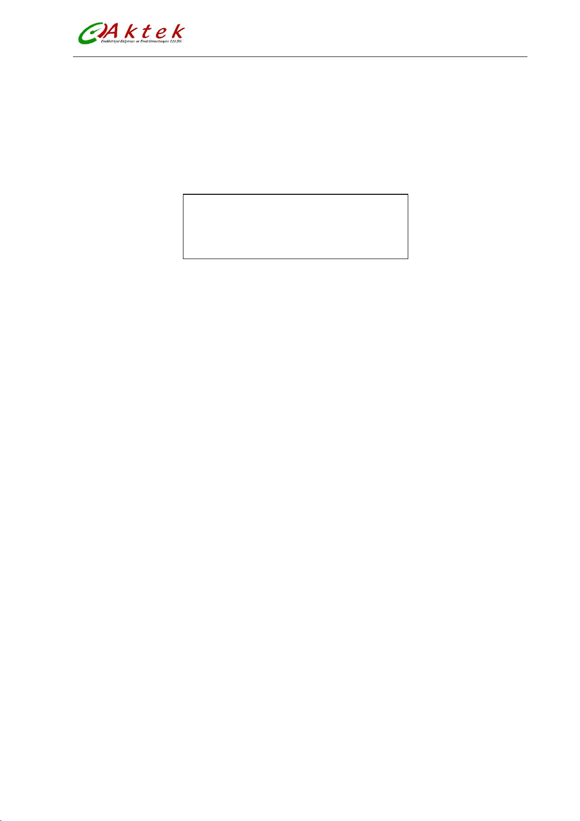
Figure (20)
Converter’s zero-flow correction displays like this:
Upper small words: FS means measure value of zero;
Lower large words: correction value of zero.
When FS is not “0”, make FS = 0. Note: if change the value on next line and FS increases, please change the
“+, -” to correct FS to zero.
Flow zero is t he compound value of the sensor, and should be recorded in sensor list and band. The unit will
be mm/s, and the sign will be opposite with correction value.
10- Flow cutoff
Flow cutoff is set in percentage of Upper Limit Range of flow, and users can delete all Negligible Small Signals
of flow volume, velocity and percentage out of displaying and outputting them. Sometimes user can delete
output of current output signal and frequency (pulse) output signal only to have flow, velocity and
percentage being displayed.
11- Total Unit
Converter display is counter with 9 bits, and the max is 999999999.
Integrator units are L, m3 (liter, stere,).
Flow integrator value: 0.001L, 0.010L, 0.100L, 1.000L, 0.001m3, 0.010m3, 0.100m3, 1.000m3 ;
12- SegmaN Ena
When “ SegmaN Ena” is “enable”, if the flow flows, the sensor will export pulse and current。When it is
“disable”, the sensor will export pulse as “0” and current as “0” (4mA or 0mA) for the flow flows reversals.
17
Page 19
AFLO-Electromagnetic Flow Meter
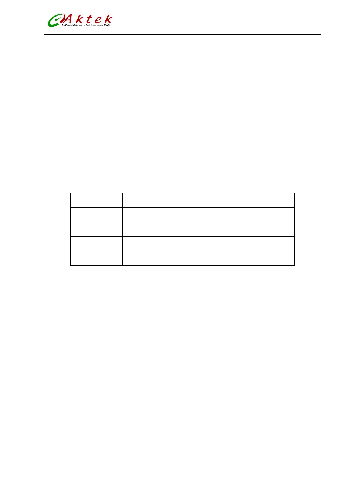
Pulse Equivalent
Flow
Pulse Equivalent
Flow
1
0.001L/cp
5
0.001m3/cp
2
0.01L/cp
6
0.01m3/cp
3
0.1L/cp
7
0.1m3/cp
4
1.0L/cp
8
1.0m3/cp
13- Output currents
Output current types can be chosen by users as 1~10mA or 4~20mA practically.
14- Pulse Type
Two kinds of Pulse Outputs can be chosen: Frequency Output and Pulse Output. Frequency Output is
continuous square waveform and Pulse output is a serial wave of square wave. Frequency output is mainly
used for instant flow and total integrated flow in short time measurement. Frequency output can be chosen
in equivalent frequency unit and volume of integrated flow can be displayed. Frequency Output can be used
in long time measurement for total integrated flow with volume units.
Frequency output and pulse output are usually from OC gates so that DC power supplies a nd load resistors
have to be required.
Equivalent pulse Unit is referred to one pulse for value of flow. The range of pulse equivalent can be chosen:
Under the same flow, the smaller pulse, the higher frequency output, and the smaller error will be. The
highest pulse output is 100cp/s.
15- Freque Max
Frequency output range is as the upper limit of flow measure, just the percent flow 100%. Frequency output
upper limit can be selected between 1~5000Hz.
16- Mtsnsr Ena
The state of empty pipe can be detected with the function of converter. In the case of Empty Pipe A larm, if
the pipe was empty, the signals of analog output and digital output would be zero and displayed flow would
be zero, too.
17- Mtsnsr Trip
When the pipe is full of liquid (whether flowing or not), the parameter of “Mtsnsr” could be modified
more easily. The parameter displayed upper line is real MTP, and the parameter displayed bellow is the
“Mtsnsr trip” that should be set. When setting “Mtsnsr trip”, you could be according to the real MTP, the
value that should be set is usually three to five times of real MTP.
18
Page 20

AFLO-Electromagnetic Flow Meter
18- Alm Hi Ena
Users can choose “Enable” or “Disable”.
19- Alm Hi Val
The parameter of upper limit alarm is percentage of flow range and can be set in the way of setting one
numerical value between 0%~199.9%.When the value of flow percentage is larger than the value of setting
value, transmitter outputs the alarm signal.
20- Alm Lo Val
The same as upper limit alarm.
21- Sys Alm Ena
Selecting Enable will have the function, and selecting Disable will cancel the function.
22- Clr Sum Key
User use more than 3 byte code to enter ,Then set this password in Clr Total Rec.
23- Snsr Code
It is referred to the produced date of sensor and the serial number of product that can keep the sensors
coefficient right and accurate.
24- Sensor Fact
“Sensor Coefficient” is printed on the Label of the sensor when it is made in factory. The “sensor coefficient”
has to be set into Sensor Coefficient Parameter when it runs with converter.
25- Field Type
AFLO affords three exciting frequency types: 1/16 frequency (type 1), 1/20frequency (type 2), 1/25
frequency (type 3). The small-bore one should use 1/16 frequency, and large-bore one should use 1/20 or
1/25 frequency. When using, please select type 1 first, if the zero of velocity is too high, select the type 2 or
type 3.
Note: Demarcate on which exciting type, working on it only.
26- FwdTotal Lo、hi
Positive total volume high byte and low byte can change forth coming and reverse total value, and be used
to maintenance and instead.
User use 5 byte code to enter, and can modify the positive accumulating volume (∑+). Usually, it is unsuitable
to exceed the maximum the counter set(999999999).
19
Page 21

AFLO-Electromagnetic Flow Meter
27- RevTotal Lo、hi
User use 5 byte code to enter, and can modify the negative accumulating volume (∑-). Usually, it is
unsuitable to exceed the minimum the counter set(999999999).
28- PlsntLmtEn
For paper pulp, slurry and other serosity, the flow measure will have "cuspidal disturb", because the solid
grain friction or concussion the measure electrode. AFLO transmitters use variation restrain arithmetic to
conquer the disturbing by designing three parameters to select disturb character.
Set it "enable", start variation restrain arithmetic; set it "disable", close variation restrain arithmetic.
29- PlsntLmtVl
This coefficient can disturb the variation of cuspidal disturb, and calculate as percent of flow velocity, thus
ten grades: 0.010m/s, 0.020m/s, 0030m/s, 0.050m/s, 0.080m/s, 0.100m/s, 0.200m/s, 0.300m/s, 0.500m/s,
0.800m/s, and the smaller percent, the higher delicacy of cuspidal restrain.
Note: when using it, must test for select by the fact, and sometimes it is not the higher delicacy is good.
30- PlsntDelay
This coefficient can select the width of time of restrain cuspidal disturb and the unit is ms. If the duration is
shorter than flow change in some time, AFLO will think it is cuspidal disturb, and if it is longer, AFLO will think
it is natural. It also needs to select parameter in fact.
31- User’s password 1~4
Users can use 5 grades of passwords to correct these passwords.
32- Analog Zero
When the converters are made in the factory, output current has been calibrated to zero scale, that is,
accurate 0mA or 4mA output.
33- Anlg Range
When the converters is made in the factory, output current have been calibrated to full scale, that is,
accurate 10mA or 20mA output.
34- Meter Fact
This fact is the special one of sensor-made-factory and the factory use this fact to unite
AFLO electromagnetic flow meters transmitters to make sure all the instruments can interchange by 0.1%.
35- MeterCode 1 and 2
Transmitter code records the date of manufacturing and serial number of converter.
20
Page 22

AFLO-Electromagnetic Flow Meter
6.6. Alarm information
Without trouble of power and hardware circuit, the normal trouble can be alarmed correctly.
This information displays on the left side of the LCD, the trouble is like this:
FQH ---- Flow high limit alarm; FQL ---- Flow low limit alarm;
FGP ---- Flow empty pipe alarm; SYS ---- System exciting alarm.
UPPER ALARM ---- Flow high limit alarm.
LOWER ALARM ---- Flow empty pipe alarm.
LIQUID ALARM ---- Flow empty pipe alarm.
SYSTEM ALARM ---- System exciting alarm.
7. Troubleshooting
7.1.No display
a) Check the power supply connection
b) Check the power fuse to see for OK
c) Check the contrast of LCD and regulate it to working state
7.2.Exciting alarm
a) Check if the exciting cables EX1 and EX2 did not connected
b) Check if the total resistance of sensor’s exciting coil resistances less than 150Ω
c) If a) and b) are OK, the converter is failed
7.3.Empty pipe alarm
If sensor is full of measured fluid, When shorting circuit three connectors SIG 1, SIG 2, SGND of converter,
and no “Empty Alarm” displayed then the converter works fine. In this case, it is possible that
conductivity of measured fluid may be small or empty threshold of empty pipe and range of empty pipe
are set wrongly.
Check the signal cable, and check the electro-poles.
Stop the flow rate, then the displayed conductivity should be less than 100%.
Resistances of SIG1 to SGND and SIG2 to SGND are less than 50kΩ (conductivity of water) during
measurement operation.
DC voltage should be less than 1V between DS1 and DS2. If DC voltage is larger than 1V, the electro
poles of sensor were polluted that have to be cleaned.
21
Page 23
AFLO-Electromagnetic Flow Meter
8. MOUNTING CONDITIONS
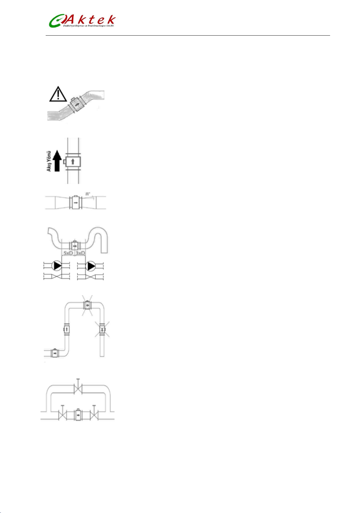
CAUTION
Sensor should always be full with fluid.
The direction of flow in vertical pipes must be upward.
In case of sensor nominal size is less than pipe size reduction
should be done with 8° angle.
Straight pipe length should be at least 5x pipe DI after elbows, pumps and valves in
upstream side and in downstream side 3x pipe DI before.
Bubbles and distortion avoidance.
Easy to maintenance and clean-up by bypass line.
22
Page 24

AFLO-Electromagnetic Flow Meter
9. SHIPPING AND STORAGE CONDITIONS
Keep the product in its original packaging to avoid damage to the product installation. Product should be kept in
storage in the following conditions.
- Protect from rain and humidity
- Protect from high vibration and shock
- Ambient temperature: -20…+60 oC
- Humidity must be less than 80%
NOTE:
Because of AKTEK’s policy of improving their products, the AFLO, would be revised and
improved. Please inform us about misunderstandings or errors which you may find in this
manual comparing it to the device you bought. Do not hesitate to contact us to suggest how to
improve our devices.
Thank You
İMES sanayi sitesi B Blok 204. Sk. No:40
Y.Dudullu Ümraniye - İstanbul
Tel:0216 540 7300 Faks: 0216 540 7303
23
 Loading...