

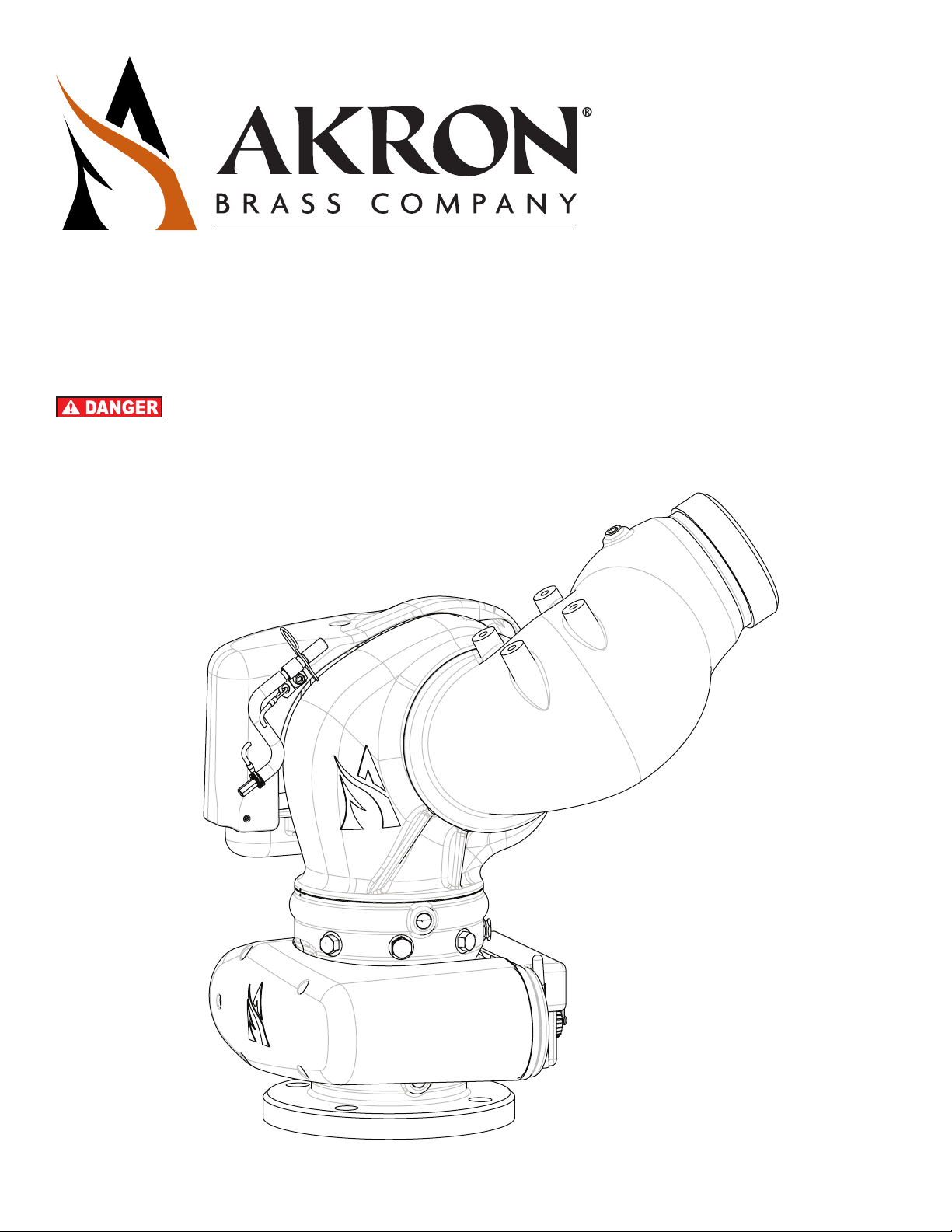
STYLE 3480, 3482 STREAMMASTER II™ ELECTRIC MONITOR
INSTALLATION, OPERATING, AND MAINTENANCE INSTRUCTIONS
The following is intended to provide the basic instructions for installation, operation and maintenance. Read
and understand these operating instructions before use.
123966
Electrical Specifications
12-VOLT SYSTEM
(11-14 Volts DC)
MOTOR
Elevation 14.0 Amps 3.0-10.0 Amps 7.5 Amps 2.0-5.0 Amps
Rotation 14.0 Amps 3.0-10.0 Amps 7.5 Amps 2.0-5.0 Amps
Pattern 3.0 Amps 3.0 Amps 1.5 Amps 1.5 Amps
Maximum
Operating Current
Normal
Operating Current
Maximum
Operating Current
24-VOLT SYSTEM
(22-28 Volts DC)
Mechanical Specifications
Parameter US Measure Metric Measure
Flow Rate 2000 GPM 7600 LPM
Pressure 250 PSI 17 Bar
Mass 40.7 Lbs 18.5 kg
Tools Required
• Wrench for flange mounting bolts
Safety Symbols
Normal
Operating Current
Indicates a hazardous situation which, if not avoided, WILL result in death or serious injury
Indicates a hazardous situation which, if not avoided, COULD result in death or serious injury
Indicates a potentially hazardous situation which, if not avoided, may result in minor or moderate injury
Address practices not related to personal injury
Product Warnings, Cautions and Notices
Charge the unit slowly. Rapid charging may cause a pressure surge that has the potential to cause an injury,
or damage the monitor.
Do not stow or deploy the monitor while flowing. Pressing the Stow or Deploy buttons causes the nozzle to
move automatically and the water stream may cause damage to equipment or injury to personnel.
Aim the unit in a safe direction before pumping water through it, e.g., away from power lines.
Do not use the electric controls when the manual override cranks are being used or are in position for use.
Make the connection of the vehicle and auxiliary battery the final step.
Do not exceed the maximum pressure or flow ratings of the monitor. Exceeding these ratings may lead to an
injury or may cause damage to the monitor.
Do not install shutos on the outlet of the monitor. Shutos increase the potential for pressure surges
due to water hammer, which have the potential to cause an injury or damage the monitor.
Page 2
Disconnect power and disable flow before maintenance.
Keep all personnel out of the Danger Zone, in front of the outlet of the monitor when the water source is
attached. Dangerous flow velocities can cause serious injury.
Not designed for explosive environments.
Use only for firefighting by trained operators.
Ensure the thread on the nozzle swivel matches the thread on the monitor outlet. Do not over-tighten the
nozzle onto the unit.
Insucient structural support at the inlet flange can lead to failure, which has potential to cause an injury.
Do not use monitor or nozzle as a forcible entry tool.
Ensure that the monitor is returned to the Stow position after use.
During freezing conditions, the monitor must be drained to prevent damage.
The monitor, nozzle, control box, tether controller and field adjustable stops are made for optimal
performance. Do not alter in any manner.
The monitor was designed for use with Akron nozzles. Use of any other nozzles could aect the speed
or operation of the unit and should be tested before being put into service.
Replace the identification tags if they should become worn or damaged.
The monitor uses current limiting for both the monitor and nozzle. Use only appropriate
Akron Brass Company nozzles.
Designed for use in freshwater applications. If used with salt water, flush with freshwater.
For use with water or standard firefighting foams only. After use with foam, flush with freshwater.
Not recommended to mount onto a raised flange. This may cause damage to the monitor’s flange
when tightening bolts.
Use a nozzle of the same material as the monitor to eliminate the eects of galvanic corrosion.
Page 3
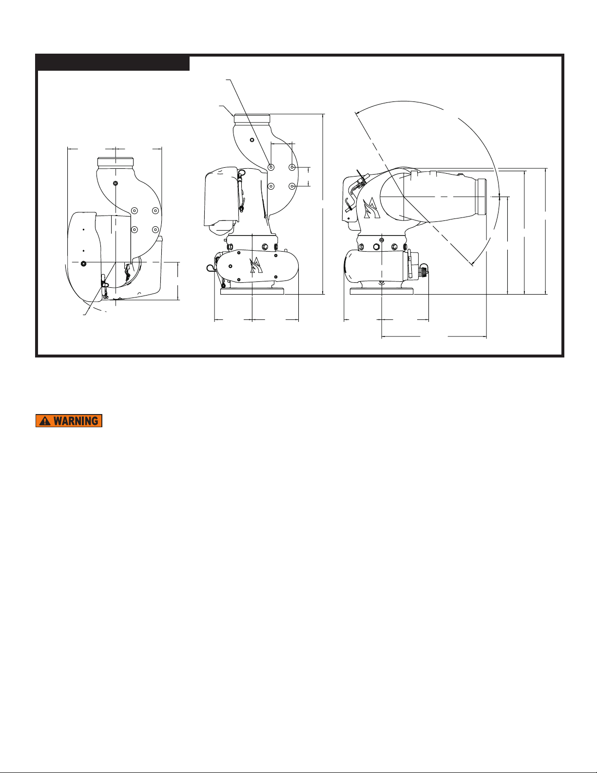
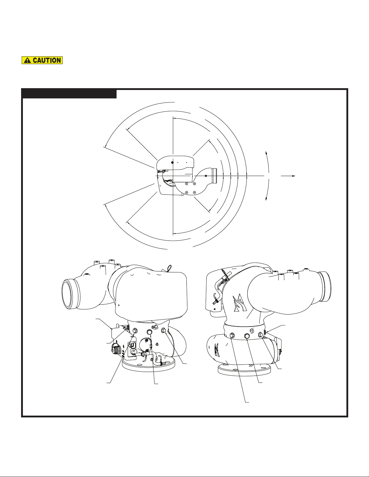
Installation
SWING RADIUS
16
12-7/ 16
5/16 - 18 UNC X 1/2 DEEP
Figure 1 – Operating Window
3 1/2 NH
THREAD
120°
5-11/16
R6
5-31/64
4-1/2
4-1/2 5-1/24-15/32
2-1/2
2-1/4
21-7/ 16
5-9/16
45°
14-15/
14-5/8
11-9/16
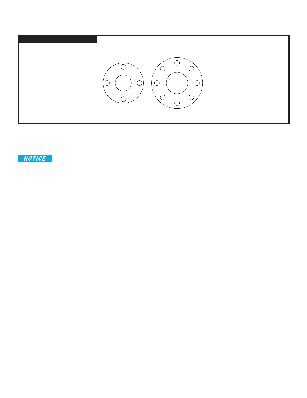
Mechanical Monitor Attachment
The monitor is to be mounted on a waterway which is capable of withstanding the pressure applied to the monitor as well as the
reaction force and resulting bending moment of the nozzle (1700 lbs at 250 PSI and 2000 GPM).
Insucient structural support at the inlet flange can lead to failure, which has potential to cause an injury.
Use 5/8" bolts and nuts of grade five minimum. Use suitable washers with a minimum of six thread engagements. Use a ring gasket
conforming to ASME 16.21. The control box is considered the front of the monitor. Use Figure 1 to position the monitor to function
within the desired operating window.
Page 4
Bolt Tightening Procedure
Start the tightening procedure by lubricating the nuts and bolts. Hand tighten the nuts until they are snug against the flange.
Figure 2 – Bolt Torque Order
1
4
2
3
4
1
7
6
5
3
8
2
The final torque of the bolts should be 85–90 ft-lbs. Following the correct sequential order, tighten the bolts to 30% of the final
torque. Repeat the tightening sequence to 60% of the final torque. Repeat a third time to 100% of the final torque. Finally, repeat the
sequence at the final torque.
Not recommended to mount onto a raised face flange. This may cause damage to the monitor’s flange when
tightening bolts.
Page 5
Rotational Stops
177-1/2°
45° LEFT
FR
The StreamMaster II™ has 355º of total rotation. Stops can be inserted to limit travel to the left or to the right according to figure 3.
Factory default stops are set at 90º to the right and left. The permanent stop must not be removed. The stops and plugs have a ½”
hex head. If a hole does not have a stop, it should have a plug.
Operating the monitor without the permanent travel limit stops in place could cause damage to the
monitor and could potentially injure the operator.
Figure 3 – Rotational Stops
135°
90°
CONTROL BOX
ONT OF MONITOR
157.5° LEFT AND RIGHT
PERMANENT STOP
DO NOT REMOVE
177-1/2°
135°
45° RIGHT
90°
45°
45°
LEFT ROTATION
(COUNTERCLOCKWISE)
FRONT
RIGHT ROTATION
(CLOCKWISE)
157.5° LEFT AND RIGHT
PERMANENT STOP
DO NOT REMOVE
135° LEFT
135° RIGHT
90° RIGHT
FACTORY DEFAULT
Page 6
90° LEFT
FACTORY DEFAULT

Elevation Stops
MONITOR SHOWN WITH DECRATIVE COVER REMOVED.
The StreamMaster II™ has 120° of travel above horizontal and 45º below horizontal, which is limited by the permanent stop. This stop
should not be removed. Stops can be inserted to limit travel above and below horizontal according to figure 4. Factory default stops
are set at 45° above horizontal and 45° below horizontal. The stops and plugs have a 5/8" hex head. If a hole does not have a stop, it
should have a plug.
Operating the monitor without the permanent travel limit stops in place could cause damage to the monitor
and could potentially injure the operator.
Figure 4 – Elevation Stops
120°
PT A
(PERMANENT)
90°
PT Y
-45°
PT A
(PERMANENT)
45°
PT Z
(FACTORY
SET)
-15°
PT B
PT A
PT Y
PT B
PT Z
Nozzle Installation
The nozzle should be threaded onto the outlet of the monitor. Position the pattern actuator in a position that does not stretch the
power cord, and then tighten the swivel. Verify that the actuator orientation does not interfere with the monitor.
Ensure the thread on the nozzle swivel matches the thread on the monitor outlet. Do not over-tighten the
nozzle onto the unit.
Use a nozzle of the same material as the monitor to eliminate the eects of galvanic corrosion.
Page 7

Electrical Installation Instructions
The StreamMaster II Controller requires Vehicle Power and CAN connections. For a description of Akron Brass harnesses that can be
used to make these connections, see the table below and figure 5. If it is desired to make harnesses, refer to figures 6 and 7, and the
accompanying table for a description of the StreamMaster II mating connectors.
HARNESSES FOR CONNECTING STREAMMASTER II CONTROLLER TO CAN DEVICES (See Figure 5)
Item Description Length
Receptacle Connector – CAN “Y” Adapter (Deutsch #DT04-3P-P007). Connects together two CAN Network Har-
1
nesses and one CAN Stub Harness.
Plug Connector – CAN 120 Terminator (Deutsch #DT06-3S-PP01). Two are required per system and plug into the
2
CAN “Y” Adapters at each end of the CAN network.
½ ft. (0.15 m)
2 ft. (0.61 m)
CAN Network Harness – Extends the CAN network to a CAN node device (an operator station for example).
3
Connects between two CAN “Y” Adapters.
4 CAN Stub Harness – Connects the CAN network to the 6052 StreamMaster II Controller 3 ft (0.91 m) 721589
CAN Stub Harness – Connects the CAN network to a 6035 Joystick, 6041 Switch Box or 6036 Direction Indicator.
5
Includes power and ground wires for connecting power to the control devices.
CAN Stub Harness – Connects the CAN network to a 6037 CAN Wireless Module. Includes power and
6
ground wires for connecting power to the module. Also includes four wires for switch inputs and two
wires for digital outputs.
CAN Stub Harness – Connects the CAN network to a 3406 Electric Riser via the 6033 Mini Universal Controller.
7
Includes four wires for the Extend and Retract Relay contacts.
8 Power Harness – Connects Vehicle Power to the StreamMaster II Controller. 8 ft. ( 2.44 m) 721682
3 ft. (0.91 m)
5 ft. (1.52 m)
10 ft. (3.05 m)
20 ft. (6.10 m)
30 ft. (9.14 m)
40 ft. (12.19 m
3 ft. ( 0.91 m)
10 ft. ( 3.05 m)
3 ft. ( 0.91 m) 721580
3 ft. ( 0.91 m) 721594
Akron Brass
Part Number
758306
742205
721569
721667
721572
721573
721574
721570
721665
721575
721579
721677
Page 8

Figure 5 – Harness Connections Between StreamMaster II Controller and CAN Devices
111
67
STREAMMASTER II
CONTROLLER
4
1
2
6052
6035 CAN JOYSTICK
6041 CAN SWITCH BOX
6041 CAN TETHER
8
VEHICLE POWER
REQUIRED FOR
STREAMMASTER II
3333
55
VEHICLE POWER
REQUIRED FOR
JOYSTICK OR
SWITCH BOX OR
TETHER
1
VEHICLE POWER
REQUIRED FOR
DIRECTION INDICATOR
6037 CAN WIRELESS MODULE6036 CAN DIRECTION INDICATOR
DIGITAL
INPUTS
DIGITAL
OUTPUTS
VEHICLE POWER
REQUIRED FOR
WIRELESS MODULE
3406 ELECTRIC RISER
6033 MINI UNIVERSAL CONTROLLER
RELAY 1
OUTPUTS
WITH
RELAY 2
OUTPUTS
2
Page 9

MATING CONNECTORS FOR STREAMMASTER II CONTROLLER (See Figures 6 and 7)
3
VEHICLE BATTERY (+)
POSITION 1
POSITION 2
VEHICLE BATTERY (−)
1
2
Item Description
Connector – DTP plug, 2 position, 0.134-0.195" (3.40-4.95 mm) wire diameter range,
1
end cap, gray
2 Wedgelock – For DTP 2-socket plug, orange
3 Contact – Solid socket, size 12, 14-12 AWG (2.5-4.0 mm2), 25 amps
Connector – DT plug, 4 position, 0.053-0.120" (1.35-3.05 mm) wire
4
diameter range, enhanced seal retention, shrink boot adapter, black
5 Wedgelock – For DT 4-socket plug, enhanced seal retention, green
6 Contact – Solid socket, size 16, 20-16 AWG (0.5-1.5 mm2), 13 amps
Figure 6 – Power Connector
Manufac-
turer
TE Connectivity
(Deutsch IPD)
TE Connectivity
(Deutsch IPD)
TE Connectivity
(Deutsch IPD)
TE Connectivity
(Deutsch IPD)
TE Connectivity
(Deutsch IPD)
TE Connectivity
(Deutsch IPD)
Manufac-
turer
Akron Brass
Part Num-
Part Number
DTP06-2S-E003 742227
WP-2S 784188
0462-203-12141 707583
DT06-4S-CE13 742203
W4S-P012 784199
0462-201-16141 769635
ber
VEHICLE BATTERY (+)
POSITION 1
3
VEHICLE BATTERY (−)
Figure 7 – CAN Connector
CAN HIGH (+)
POSITION 3
CAN LOW (−)
POSITION 4
POSITION 2
6
1
2
4
5
POSITION 2
VEHICLE POWER (−)
OUT TO CAN DEVICES
POSITION 1
VEHICLE POWER (+)
OUT TO CAN DEVICES
Page 10

INITIAL SYSTEM SETUP
The StreamMaster II allows many configuration options during setup.
The following functions can be configured in the setup mode:
• Right, Left, Up and Down Soft Limit Positions
• Monitor Orientation (sideways or inverted mounting)
• Position Sensor “Zero”
• Restore Factory Defaults
• Obstacle Avoidance
• Electric Riser Disable/Enable
• Stow and Deploy Positions
To enter the setup mode for the above functions, follow these steps:
1. Turn power o to StreamMaster II
2. Press and HOLD the Stream switch (can be done on the Joystick or the Toggle Switch Box)
3. Turn power on to StreamMaster II while continuing to hold the Stream switch
4. Wait 3-4 seconds and release the Stream switch
The StreamMaster II should now be in setup mode. When in setup mode, the LED on the operator station will be slowly blinking (a
short blink followed by a long pause). If it is not slowly blinking, turn the power o and repeat steps 1-4.
All setup functions except the Stow and Deploy Positions can be scrolled through by pressing the Stream switch. Each time the
Stream switch is pressed, another function is active for configuration. If a function is configured and saved using the Fog switch, the
next function will be automatically selected. For example, the first time the Stream switch is pressed, the Right Soft Limit Position
(LED Code 1-1) is ready for programming. If it is pressed again, the Left Soft Limit Position (LED Code 1-2) is ready for programming.
If the Left Soft Limit Position is set and the Fog switch is pressed, the Up Soft Limit Position (LED Code 1-3) will be automatically
selected without having to press Stream again. Alternatively, activating the Stream command will abort this function without storing
the position and the next function will be selected. Entering the Stow and Deploy Positions programming modes can only be accomplished by activating the Stow or Deploy switch while at the start of the setup menu (LED Code 1 Slow blink). (See the sections for
Stow Position and Deploy Position for more detail).
To aid in determining which setup menu the StreamMaster II is in, the LED on the operator station has been programmed to blink a
dierent code for each function. The table below lists the LED codes for each function. The codes have two parts. The LED code will
start with either one or two short blinks, a short pause, another series of short blinks, and then a long pause. The first number in the
LED code is the one or two blinks and the second number is the second series of blinks before the long pause. There is also an LED
on the front of the 6052 StreamMaster II Controller that will display the status codes. The controller is mounted at the base of the
monitor.
Page 11

Any of the following functions may be configured by stopping at that function and performing the operation. See the appropriate
section for detailed information on configuration of each function.
Setup Menu Function LED Code
Setup Mode Start 1 slow blink
Right Soft Limit Position 1-1
Left Soft Limit Position 1-2
Up Soft Limit Position 1-3
Down Soft Limit Position 1-4
Monitor Orientation 1-7
Position Sensor “Zero” 1-8
Restore Factory Defaults 1-9
Obstacle Avoidance Disable 2-1
Obstacle Avoidance Manual Operation 2-2
Obstacle Avoidance Auto Operation 2-3
Obstacle Avoidance Learn 2-4
Electric Riser Disable 3-1
Electric Riser Enable 3-2
Stow Position 1-5
Deploy Position 1-6
Setup Mode Table for LED Codes
While any and all of these configurations are optional, if a monitor orientation is mounted sideways or inverted, the monitor
orientation will need to be configured for proper operation. If at any point it is determined that an undesirable mode is active, it is
possible to abort the mode by removing power to the StreamMaster II prior to activating the Fog input. If it is determined that an
undesired function may have been saved, it may be desirable to use the “Restore Factory Defaults” function (LED Code 1-9). When all
desired changes have been made, cycling power will return the monitor to normal operation and the changes that were made will be
in eect. The changes can also be saved by pressing the Fog switch when in setup start mode (one single blink).
The position sensors are “zeroed” at the factory. The default zero position is facing straight ahead with the nozzle level (0º elevation). If the monitor is physically mounted such that this is not the zero position for your installation, you will need to re-zero the
monitor before it can be used with a 6036 Direction Indicator.
Soft limits can be set to shorten the rotational and elevation range. NOTE: Use of this function will clear all stored obstacle avoid-
ance option profile data and require the obstacle avoidance to be re-programmed. Factory defaults are set to a soft limit location
beyond the hard stops so that the monitor will have full range of motion between hard stops until the soft limits are set.
Page 12

Right Soft Limit Position (Blink Code 1-1)
In this mode, Right, Left, Up and Down functions will be active. Move the monitor to the position that is to be set as the Right
Soft Limit. When in the desired position, press the Fog switch. The new Right Soft Limit is now set and the Left Soft Limit is
active for programming. Alternatively, activating the Stream command will abort this mode without storing the position and the
Left Soft Limit Position mode will be automatically selected.
Left Soft Limit Position (Blink Code 1-2)
In this mode, Right, Left, Up and Down functions will be active. Move the monitor to the position that is to be set as the Left
Soft Limit. When in the desired position, press the Fog switch. The new Left Soft Limit is now set and the Up Soft Limit is active
for programming. Alternatively, activating the Stream command will abort this mode without storing the position and the Up Soft
Limit Position mode will be automatically selected.
Up Soft Limit Position (Blink Code 1-3)
In this mode, Right, Left, Up and Down functions will be active. Move the monitor to the position that is to be set as the Up
Soft Limit. When in the desired position, press the Fog switch. The new Up Soft Limit is now set and the Down Soft Limit is
active for programming. Alternatively, activating the Stream command will abort this mode without storing the position and the
Down Soft Limit Position mode will be automatically selected.
Down Soft Limit Position (Blink Code 1-4)
In this mode, Right, Left, Up and Down functions will be active. Move the monitor to the position that is to be set as the Down
Soft Limit. When in the desired position, press the Fog switch. The new Down Soft Limit is now set and the Monitor Orientation
is active for programming. Alternatively, activating the Stream command will abort this mode without storing the position and
the Monitor Orientation mode will be automatically selected.
Monitor Orientation (Blink Code 1-7)
There are instances when it is desirable to mount the monitor other than in the factory default “flange on the bottom” position.
In those instances, this function prevents having to change the wiring of switches or re-programming CAN joysticks to handle
changes in Up/Down – Left/Right behavior. It is only necessary to program the monitor orientation when the monitor is
mounted on its side or upside down. When in this mode, determine which of the four inputs (Up, Down, Left, or Right) results
in “Up” movement. The last movement made prior to pressing the Fog switch will be used as the new “Up” motion and will remap
the other inputs accordingly. Move the monitor in whatever the current “Up” motion is and then press the Fog switch. The
new Monitor Orientation is now set and the Position Sensor “Zero” is active for programming. If the Stream switch is pressed
at any time before the Fog switch, the Monitor Orientation will remain unchanged and the Position Sensor “Zero” mode will be
automatically selected. NOTE: Use of this function will clear all stored obstacle avoidance profile data and require the
obstacle avoidance option to be reprogrammed.
Position Sensor “Zero” (Blink Code 1-8)
It is often dicult for the vehicle manufacturer to mount the monitor in the precise position where “straight ahead and level”
matches the calibration of the monitor at the Akron Brass factory. Use of this mode allows the user to “re-zero” the sensors at
the desired “straight ahead and level” position. First, use the Left/Right and Up/Down switches to position the monitor
“straight ahead and level”. When the desired position has been reached, press the Fog switch. The new “zero” position is now
set and the Restore Factory Defaults mode is now active for programming. If the Stream switch is pressed at any time before
the Fog switch, the position sensor values will remain unchanged and the Restore Factory Defaults mode will be automatically
selected. NOTE: The soft limits positions, stow/deploy positions and CAN position reporting will be impacted by “re-zeroing”.
If “re-zeroing” is needed, do so before setting soft limit, stow or deploy positions. NOTE: Use of this function will clear all
stored obstacle avoidance profile data.
Page 13

Restore Factory Defaults (Blink Code 1-9)
Occasionally, it may be desirable to return to factory defaults. To restore factory defaults when in this mode, press the fog switch.
This will clear all user selected settings and return to the start of the setup menu (LED Code 1 Slow blink). The following settings
will be reset to factory default:
• All soft limit positions will get set to maximum.
• Position sensor “zero” values will return to the values set at the factory.
• Monitor orientation will get reset to standard position.
• Stow and Deploy positions are reset to zero degrees as established at the factory.
• Obstacle Avoidance profile data is cleared and disabled.
It is possible to abort this mode prior to activating the Fog input by simply removing power to the StreamMaster II. Alternatively,
activating the Stream command will abort this mode without restoring factory defaults and the Obstacle Avoidance Disable (Blink
Code 2-1) mode will be automatically selected.
Obstacle Avoidance Disable (Blink Code 2-1)
Pressing the Fog switch will Disable Obstacle Avoidance, clear the Obstacle Avoidance Profile and return to the start of the
setup menu (LED Code 1 Slow blink). The factory default setting for obstacle avoidance is DISABLED. Alternatively, activating the
Stream command will abort this mode without disabling obstacle avoidance and the Obstacle Avoidance Manual Operation mode
will be automatically selected.
Obstacle Avoidance Manual Operation (Blink Code 2-2)
Manual operation mode requires the operator to manually move the monitor around obstacles. When an obstacle is encountered,
movement in that direction stops until the operator moves the monitor around the obstacle. Pressing the Fog switch will select
Manual Operation for Obstacle Avoidance. Alternatively, activating the Stream command will abort this mode without selecting
Manual Operation and the Obstacle Avoidance Auto Operation mode will be automatically selected.
Obstacle Avoidance Auto Operation (Blink Code 2-3)
Auto operation mode does not require the operator to move up and down to go around an obstacle. When an obstacle is encountered, movement in that direction stops and the StreamMaster II automatically navigates up, over, and back down around the obstacle as long as the joystick is maintained in the horizontal command (right or left). Pressing the Fog switch will select Auto Opera-
tion for Obstacle Avoidance. Alternatively, activating the Stream command will abort this mode without selecting Auto Operation
and the Obstacle Avoidance Learn mode will be automatically selected.
Page 14

Obstacle Avoidance Learn (Blink Code 2-4)
This function sets the Lower Limits across the horizontal range of the monitor. For instance, a monitor located on the center of
a cab roof might need to raise the nozzle slightly to avoid hitting the corners of the cab as it sweeps from side to side. Use of
this mode allows the user to program a horizontal profile that will go around one or more obstacles. As the monitor is moved
from side to side (either right to left, or left to right), the vertical position values are stored at one degree increments. Backing up
will overwrite previous data. If a horizontal area is not learned, that area will be inaccessible later. To program an obstacle
avoidance profile, follow these steps:
1. Enable either manual or automatic obstacle avoidance.
2. Move the monitor to the lower left or right, or the lower right soft limit.
3. Sweep until the first obstacle is encountered. Stop movement before the obstacle is reached.
4. Move horizontally up over and back down until the obstacle is cleared.
5. Continue moving toward the opposite side. Repeat steps 2 and 3 if any other obstacles are encountered.
6. When the opposite horizontal soft limit is reached, press the Fog switch. This will save the new Obstacle Avoidance Profile and
return to the start of the setup menu (LED Code 1 Slow blink).
The same procedure can also be followed from right to left. It is important that the entire rotational range is covered during the
programming procedure. Activating the Stream command will discard any profile data that has already been saved and will return
to the start of the setup menu (LED Code 1 Slow blink).
Electric Riser Disable (Blink Code 3-1)
This function disables the 3406 Electric Riser from working with the deploy and stow sequences of the monitor. This is the factory
default setting.
Electric Riser Enable (Blink Code 3-2)
This function enables the 3406 Electric Riser to work with the deploy and stow sequences of the monitor. During the deploy
sequence, the electric riser will first extend to lift the monitor up and then the monitor will deploy. During the stow sequence,
the monitor will first stow and then the electric riser will retract to lower the monitor down.
Stow Position (Blink Code 1-5)
To enter the Stow Position programming mode, momentarily press the Stow switch when at the beginning of the setup mode
(LED Code 1 Slow blink). Verify the Stow Position programming mode by observing the blink code (one short blink, a short pause,
then five short blinks, and a long pause). In this mode, Right, Left, Up and Down functions will be active. Movement will not be
constrained by soft limits, thus allowing a stow position that is outside of the normal operational envelope. However, obstacle
avoidance will be disregarded while learning the Stow Position, so care must be taken to avoid obstacles manually. When at the
desired Stow Position, there are two methods of completion. (1) Activating the Fog command will save the position and also cause
the nozzle to go to the fog setting during the stow sequence. The beginning of the setup menu (LED Code 1 Slow blink) will then
be returned to. (2) Activating the Stream command will save the position and also cause the nozzle to go to the stream setting
during the stow sequence. The beginning of the setup menu (LED Code 1 Slow blink) will then be returned to. Activating the Stow
command again will abort this function and return to the start of the setup menu (LED Code 1 Slow blink). The factory default
Stow Position is “straight ahead and level” as defined by the sensor zeroing (see the Position Sensor “Zero” section).
Deploy Position (Blink Code 1-6)
To enter the Deploy Position programming mode, momentarily press the Deploy switch when at the beginning of the setup
mode (LED Code 1 Slow blink). Verify the Deploy Position programming mode by observing the blink code (one short blink, a short
pause, then six short blinks, and a long pause). In this mode, Right, Left, Up and Down functions will be active. Movement will be
constrained to whatever soft limits are in eect. However, obstacle avoidance will be disregarded while learning the Deploy
Position, so care must be taken to avoid obstacles manually.
Page 15

When at the desired Deploy Position, there are two methods of completion. (1) Activating the Fog command will save the
position and also cause the nozzle to go to the fog setting during the deploy sequence. The beginning of the setup menu (LED
Code 1 Slow blink) will then be returned to. (2) Activating the Stream command will save the position and also cause the nozzle to
go to the stream setting during the deploy sequence. The beginning of the setup menu (LED Code 1 Slow blink) will then be
returned to. Activating the Deploy command again will abort this function and return to the start of the setup menu (LED Code 1
Slow blink). The factory default Deploy Position is “straight ahead and level” as defined by the sensor zeroing (see the Position
Sensor “Zero” section).
Operating Instructions
6041 CAN Toggle Switch Box
The Stow/Deploy switch is used to move the monitor in and out of its stow position for transit. Pushing and holding the Stow/
Deploy toggle switch forward for at least two seconds will initiate a deploy sequence placing the monitor in position for
normal operation. Pulling and holding the Stow/Deploy toggle switch backward for at least two seconds will initiate a stow
sequence placing the monitor in position for transit.
The Oscillation (Start/Set)/(Pause/Resume) switch is used to teach and control a horizontal oscillation pattern. Pushing the
Oscillation toggle switch forward, the monitor rotation will be driven toward the right until either: the switch is released, a
soft-limit is encountered or a hard-limit is encountered. That point will be assigned the rightmost travel point in the auto oscillate profile. The monitor will again automatically reverse direction and move to the left until the “Set/Start” switch is
pushed and released, a soft-limit is encountered or a hard-limit is encountered. That point will be assigned the leftmost travel
point in the auto-oscillate profile. The monitor will then automatically oscillate back and forth between those two points until
either: the Oscillation switch is pulled backward to the “Pause/Resume” position, a Left or Right command is received from
a switch or joystick input or some other disabling function is encountered. Pulling the Oscillation switch backward to the
“Pause/Resume” position will only pause oscillation, and pulling the Oscillation switch backward to the “Pause/Resume”
position switch a second time will cause oscillation to be resumed using the taught positions. Use of a Left or Right command
will cancel oscillation and the profile will be cleared. The monitor can be moved up and down during oscillation without
cancelling the oscillation function.
The Discharge On/O/Remote switch is used to control the discharge valve that is connected to the StreamMaster II. Pushing
the Discharge switch to the “On” position will cause the discharge valve to be turned on regardless of any external device
(joystick) until the switch is returned to the “Remote” or “O” position. The switch is maintained in that position and will not
return to center on its own. When the Discharge switch is pulled backward to the “O” position, the Discharge valve will be
turned o regardless of any external device (joystick) until the switch is returned to the “Remote” or “On” position (center).
When the switch is in the center or “Remote” position, control of the discharge valve is turned over to the state of other
network devices (i.e. Joystick trigger).
For further detail, refer to the: Style 6041 CAN Toggle Switch Box – Installation, Operation & Maintenance Manual
6035 CAN Joystick
The joystick is proportional in the X and Y axis. Pushing the joystick forward will lower the monitor nozzle. The farther forward
the joystick is pushed, the faster will be the motion. Pulling the joystick back will raise the monitor nozzle. Moving the joystick to
the right will rotate the monitor to the right. Moving the joystick to the left will rotate the monitor to the left.
The “trigger” switch is used to open and close the water/foam discharge valve. (This assumes the discharge valve has been wired
to the appropriate output on the StreamMaster II). Squeezing the trigger switch will open the valve, and releasing the trigger
switch will close the valve. The valve may be placed in a continuously open condition by “double-clicking” the trigger switch. The
next activation of the trigger switch will return it to normal momentary operation.
On top of the joystick is a thumb switch used to control the pattern sleeve of the nozzle. Moving the thumb switch to the righ
will move the pattern sleeve towards the straight stream position. Moving the thumb switch to the left will move the pattern
sleeve towards the fog position. In both cases, the pattern sleeve will stop when the thumb switch returns to center position,
or the pattern sleeve reaches the full extent of its travel. This permits a continuously adjustable discharge pattern.
For further detail, refer to the: Style 6035 CAN Joystick – Installation, Operation & Maintenance Manual
Page 16

Error Codes
Error codes are a two part blink code consisting of one or two short blinks, short pause, followed by a second set of blinks for the
specific code, then, a long pause. After the long pause, the code will repeat. During the pause between codes, the LED is on.
1-1 Rotation Sensor:
SWITCH: The rotation switch was not detected as part of a stow/deploy sequence.
POSITION FEEDBACK: The rotation position feedback sensor signal is missing or not changing while the monitor is moving.
1-2 Elevation Sensor:
SWITCH: The elevation switch was not detected as part of a stow/deploy sequence.
POSITION FEEDBACK: The elevation position feedback sensor signal is missing or not changing while the monitor is moving.
1-3 Swing Arm Sensor error:
3440 DeckMaster only: The swing arm hit a hard stop instead of stopping on the sensor
1-4 Attitude Sensor error:
3351 Tuckaway with autolevel only
1-5 Operator Override:
During a Stow/Deploy sequence, a command input was received which interrupted the sequence (emergency stop) or an ob
stacle was hit causing the monitor to stop before completing the sequence.
1-6 Obstacle Avoidance Profile Needed:
The obstacle avoidance feature was turned on, but an avoidance profile was not learned.
1-7 Rotation Hard Stop:
(position feedback units only) A hard stop was encountered during normal rotation. This is an unexpected condition and
could be a sensor problem or an obstruction was hit.
1-8 Elevation Hard Stop
(position feedback units only) A hard stop was encountered during normal elevation. This is an unexpected condition and
could be a sensor problem or an obstruction was hit.
1-9 Swing Arm Hard Stop
3440 DeckMaster Only. The Swing Arm hit an obstruction between stow and deploy positions.
2-1 Electric Riser:
Electric riser function is turned on but the riser is not available on the network.
Maintenance Instructions
• The monitor should be kept clean and free from dirt.
• Inspect for damaged components or wiring and repair or replace as needed.
• The monitor should move freely and smoothly without hesitating.
• Inspect monitor for leaks. Replace seals as needed. Use Parker O-Ring lubricant on O-Rings.
• Grease fittings are installed at worm gear and ball bearing joints. If motor is laboring or movement of the joint is not smooth,
grease until normal operation is restored. Do not over-apply grease using a grease gun. Pressure will build in the monitor cavity
and could cause damage to the monitor. The elevation joint bearings do not require grease.
Warranty Statement
WARRANTY AND DISCLAIMER*: We warrant Akron Brass products for a period of five (5) years* after purchase against defects
in materials or workmanship. Akron Brass will repair or replace product which fails to satisfy this warranty. Repair or replace
ment shall be at the discretion of Akron Brass. Products must be promptly returned to Akron Brass for warranty service. We will
not be responsible for: wear and tear; any improper installation, use, maintenance or storage; negligence of the owner or user;
repair or modification after delivery; failure to follow our instructions or recommendations; or anything else beyond our control.
WE MAKE NO WARRANTIES, EXPRESS OR IMPLIED, OTHER THAN THOSE INCLUDED IN THIS WARRANTY STATEMENT, AND WE
DISCLAIM ANY IMPLIED WARRANTY OF MERCHANTABILITY OR FITNESS FOR ANY PARTICULAR PURPOSE. Further, we will not
be responsible for any consequential, incidental or indirect damages (including, but not limited to, any loss of profits) from any
cause whatsoever. No person has authority to change this warranty. Unless otherwise provided herein, Akron Brass industrial
electronic components & the Severe-Duty Monitor have a one (1) year warranty. Select Akron Brass handline nozzles and valves
carry a ten (10) year warranty. Weldon products have a two (2) year warranty from date of manufacture (excluding consumable
components). Select Weldon LED products carry a five (5) year warranty. Honda products have the manufacturers’ warranty and
Akron Brass disclaims any warranty with respect to those products.I
ISO 9001 REGISTERED COMPANY
PHONE 800.228.1161 | www.akronbrass.com
WARRANTY AND DISCLAIMER: We warrant Akron Brass products for a period of five (5) years after purchase against defects in materials or workmanship. Akron Brass will repair or replace
product which fails to satisfy this warranty. Repair or replacement shall be at the discretion of Akron Brass. Products must be promptly returned to Akron Brass for warranty service.
We will not be responsible for: wear and tear; any improper installation, use, maintenance or storage; negligence of the owner or user; repair or modification after delivery; damage; failure to
follow our instructions or recommendations; or anything else beyond our control. WE MAKE NO WARRANTIES, EXPRESS OR IMPLIED, OTHER THAN THOSE INCLUDED IN THIS WARRANTY
STATEMENT, AND WE DISCLAIM ANY IMPLIED WARRANTY OF MERCHANTABILITY OR FITNESS FOR ANY PARTICULAR PURPOSE. Further, we will not be responsible for any consequential,
incidental or indirect damages (including, but not limited to, any loss of profits) from any cause whatsoever. No person has authority to change this warranty.
© Akron Brass Company. All rights reserved. No portion of this can be reproduced without the express written consent of IDEX Corporation.
REVISED: 3/2021
 Loading...