

[ASAHI KASEI]
[AK4170]
AK4170
Features
n Ultra smooth output waveform
n Support full speed(12Mbps) and low speed(1.5Mbps)
n Single Power Supply 3.3 volts ± 10%
n 16pin TSSOP package
n Functionally compatible to Philips PDIUSBP11
n Support suspend mode
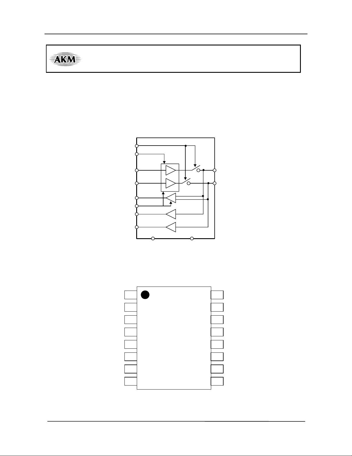
OEN
FAST
INP
INN
RDIFF
SUS
RSHP
RSHN
USB Transceiver
DP
DN
+
-
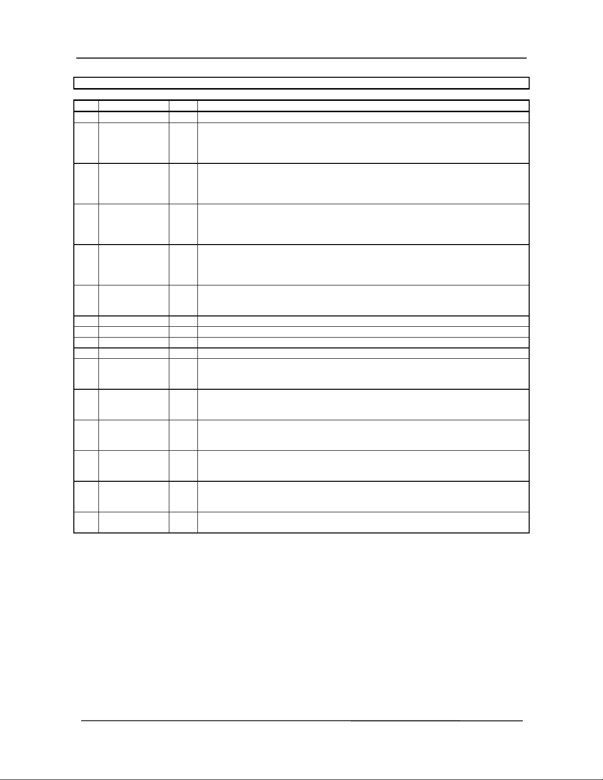
nPin Layout
OEN
RDIFF
RSHP
RSHN
SUS
VSS
NC
VSSVDD
AK4170 Block Diagram
1NC
2
3
4
5
6
7
8
16 VDD
15
INN
14
INP
13
DP
12
DN
11
FAST
10
NC
NC
9
<M0066-E-01> <1999/09>
- 1 -
[ASAHI KASEI]
Pin/Function
No. Signal Name I/O Description
1 NC - Not Connected
2 OEN I Output Enable Pin (CMOS level digital input)
Low input enables transmit data, it is that both INP and INN output onto DP and
DN pins. High input enable receive mode, which disables the outputs of DP and
DN, and the buffer goes into high-z state.
3 RDIFF O Differential Receiver Output (CMOS level digital output)
When DP > DN, the output is H. When DP < DN, the output is L.
When both DP and DN are L, the output is not guaranteed.
this pin also outputs correctly regardless of the OEN input.
4 RSHP O Schmitt Hysteresis Receiver Output for DP (D+) input (CMOS level digital output)
When DP is high level, RSHP is high.
When DP is low level, RSHP is low
this pin also outputs correctly regardless of the OEN input.
5 RSHN O Schmitt Hysteresis Receiver Output for DN (D-) input (CMOS level digital output)
When DN is high level, RSHN is high.
When DN is low level, RSHN is low
this pin also outputs correctly regardless of the OEN input.
6 SUS I Suspend Mode Control Pin (CMOS level)
High input forces the RDIFF output to low level, and the AK4170 goes into low
power consumption mode regardless of OEN pin.
7 VSS P Ground Pin
8 NC - Not Connected
9 NC - Not Connected
10 NC - Not Connected
11 FAST I Full Speed/Low Speed Control Input (CMOS digital input)
Low input activates the AK4170 to Low Speed (1.5Mbps) mode.
High input activates the AK4170 to Full Speed (12Mbps) mode.
12 DN I/O Transmitter/Receiver Negative Data Output/Input Pin
DN outputs the data of INN logic level when OEN is low
DN disable the output, and goes to high-z state when OEN is high.
13 DP I/O Transmitter/Receiver Positive Data Output/Input Pin
DP outputs the data of INP logic level when OEN is low
DP disable the output, and goes to high-z state when OEN is high.
14 INP I Transmitter Positive Data Input Pin (CMOS digital input)
When OEN is low, DP outputs INP logic level.
When OEN is high, INP does not influence output pins.
15 INN I Transmitter Negative Data Input Pin (CMOS digital input)
When OEN is low, DN outputs INN logic level.
When OEN is high, INN does not influence output pins.
16 VDD - Power Supply Pin
Connected to VSS with a 0.1uF capacitor.
[AK4170]
<M0066-E-01> <1999/09>
- 2 -
[ASAHI KASEI]
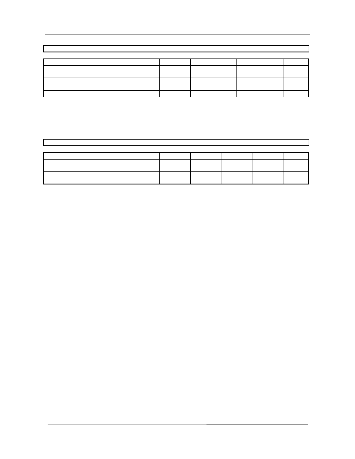
Absolute Maximum Rating
VSS=0V
Parameter Symbol min max Units
Power Supplies
VDD 4.5 V
Digital Input Voltage VIN VSS-0.3 VDD+0.3 V
Digital Output Voltage VO VSS-0.3 VDD+0.3 V
Ambient Temperature Ta -40 +125
Note 1. All voltages with respect to ground
Warning: Operation at or beyond these limits may results in permanent damage to the device. Normal operation is
not guaranteed at these extremes.
Recommended Operating Condition
VSS=0V
Parameter Symbol min typ max Units
Power Supplies
Operating Temperature
All voltages with respect to ground.
VDD 3.0 3.3 3.6 V
Ta 0 70
[AK4170]
°C
°C
<M0066-E-01> <1999/09>
- 3 -
 Loading...