

Page 1
STEREO MIXER
INSTRUCTIONS MANUAL
MANUAL DE INSTRUCCIONES
Page 2
NORMAS PARA SU SEGURIDAD
1
CAUTION
RISK OF ELECTRIC SHOCK
DO NOT OPEN
ATENCION: PARA REDUCIR EL RIESGO DE ELECTROCUCION, NO
MANIPULE ELINTERIORDELEQUIPO.
PARA REALIZAR EL MANTENIMIENTO DEL EQUIPO PONGASE EN
CONTACTO CON ELPERSONALCUALIFICADO
Esta señalindicalapresencia de lugares donde habiendo
un elevado voltaje no presentan aislamiento y por tanto
constituye un claroriesgode electrocución.
Esta señalindicalapresenciadecomponentesdelequipo
que precisan de mantenimiento. Para más información
sobre éstos leaelmanual.
WARNING
1. Lea detenidamente este manual antes de utilizar su equipo.
2. Mantenga el manual a su disposición para su uso en el futuro.
3. Siga las advertencias que se le proporcionan en este manual.
4. Siga lasinstruccionesconsignadaseneste manual, un usoindebido
podría dejar sin efecto la garantía.
5. Agua y humedad. No utilice el equipo cerca del agua o en lugares
muy húmedos (fregadero, lavadora, etc.) para evitar riesgos de
descargaeléctricaofuego.
6. Transporte del equipo. Transporte el equipo con mucho cuidado.
Los golpes o las vibraciones fuertes pueden dañarlo mecánicamente.
7. Montaje en pared o techo. Siga las instrucciones del fabricante.
8. Fuentes de calor. Tenga cuidado de no colocar el equipo cerca de
fuentes de calor (Ej. Radiadores, estufas, amplificadores, etc.)
10. Protección del cable. Escoja una posición para el cable de
corriente de modo que esté lo menos expuesto a pisotones y demás
agresiones. Especialatención con losdos extremos delcable de toma
de corriente,la clavija de enchufea la redy la clavijade alimentación
del equipo.
11. Limpieza. Desconecte el equipo antes de realizar alguna
operación de limpieza del aparato. Utilice un trapo suave y secopara
limpiar.Asegúrese de que los cables están correctamente conectados
antes de volver a enchufar el aparato.
12. Control de seguridad. La diferencia de potencial entre la toma de
corriente de la paredycualquierpiezametálicadel equipo debe ser de
al menos 100.000 ohmios.
13. Periodos largos de reposo del equipo. Desconecte el equipo de la
red en caso de reposo prolongado.
14. Líquidos y objetos extraños. En caso de que algún fluido o
pequeñas partículas sólidas sean derramadas sobre el aparato y se
introduzcan en los circuitos apague el aparato y llévelo a su
distribuidor.
15. Daños en el quipo que precisen reparación. El equipo deberá ser
reparado o revisado por personal cualificado en caso de:
A. El cable de toma de corriente o su conector han sido dañados.
B. Objetos o líquidos se han introducido en el equipo.
C. El aparato ha sido expuesto a la lluvia.
D. El equipo no parece funcionar o lo hace de modo poco usual.
E. El aparato ha caído al suelo o presenta deterioros en su caja
exterior.
16. Mantenimiento. Noabraelequipopara labores de mantenimiento
pues en este aparato no hay piezas que necesiten manutención. En
caso de queabriendoel equipo sea éstedañadoo lo sea lapersonaque
lo manipula la empresa no tomará ninguna responsabilidad por este
servicio de mantenimiento no autorizado. Además en éste caso la
garantía perdería su vigencia.
17. Ventilación. El aparato está provisto de hendiduras de
ventilación, es importante no cubrirlas o bloquearlas. La ventilación
del aparato podría verse comprometida resultando en un
sobrecalentamiento que podría dañar el equipo. Tenga siempre en
cuenta que colocar el aparato en un lugar sin ventilación puede
producir un sobrecalentamiento de éste.
18. Nunca utilice accesorios o modificaciones no autorizados por el
fabricante. Ello puede afectar la seguridad del aparato y el fabricante
no tomará ninguna responsabilidad en este caso.
19. Accesorios. No deposite o instale el equipo sobre superficies o
estructuras inestables. El aparato podría precipitarse y causar
lesiones a las personas en las proximidades de éste. Cualquier
montaje o instalación del equipo deberá ser realizado siguiendo las
instrucciones o recomendaciones dadas en este manual o por el
fabricante directamente.
20. Precaución durante tormentas. Durante una tormenta desconecte
el equipo de la red para evitar que los posibles picos de corriente
dañen el equipo.
21. Durante cualquier manipulación del equipo, paramantener todas
las cualidades deéstetantoen prestaciones como en seguridadparael
operante es necesario utilizar sólo recambios originales.
Consecuentemente asegúrese de que la empresa que realice el
mantenimiento esté autorizada por el fabricante o importador.
22. Comprobación de seguridad. Una vez realizada una reparación o
servicio del equipo pida al personal cualificado que realice una
comprobación para asegurarse de que el equipo le es devuelto en
perfectas condiciones de uso.
9. Voltaje.Antes de conectar el aparato a la red asegúrese de que se
trata del mismo voltaje y frecuencia para las que el equipo está
especificado. En caso contrario no conecte el equipo y póngase en
contacto con su distribuidor.
PARA EVITAR ACCIDENTES PROVOCADOS POR EL FUEGO O LA ELECTROCUTACION.
NO UTILICE LA CLAVIJA DE CONEXIÓN CON UN
CABLE EXTENSOR UN ADAPTADOR O CUALQUIER OTRO INTERFACE QUE DEJE PARTE DEL PIN EXPUESTO.
EN CASO DE QUE LOS PIN
DE LA CLAVIJA NO ENTREN COMPLETAMENTE EN SU POSICIÓN
PARA EVITAR ACCIDENTES PROVOCADOS POR EL FUEGO O LA ELECTROCUTACION. NO EXPONGA EL
LA LLUVIA O HUMEDAD EXCESIVA.
EQUIPO A
CUC
U
MX-2
MX-2 MX-2
Page 3
2
Es posible que este sea tu primer mezclador, es por ello
que hemos creído oportuna esta introducción donde te
prevendremos de los errores más comunes que realiza
la gente al utilizar un mezclador.
10 minutos...Léeme!
Nomenclatura
10
9
8
7
6
5
4
3
2
1
0
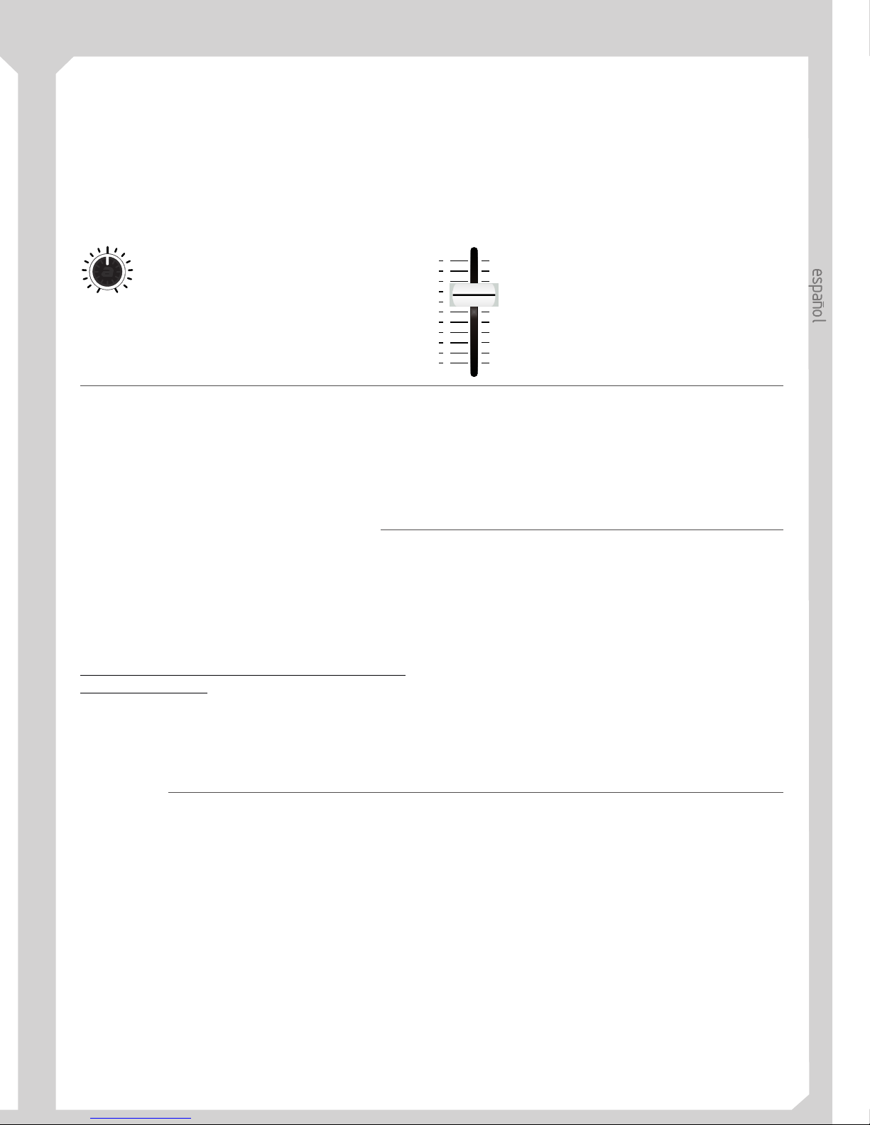
Este es el botón que controla un
potenciómetro rotativo. Lo llamaremos
Potenciómetro.
Este es el botón que controla un potenciómetro
deslizante. Lo llamaremos Fader.
Un mezclador esun equipo electrónicoque recibe señal
de distintos reproductores, la mezcla y envía su salida
(Master) a laetapa de amplificación. Esta essu función,
pero al realizarla debemos tener en cuenta
principalmente dos cosas; nivel de la señal dentro del
mezclador y saturación de laseñal.
Nivel de la señal dentro del mezclador
Cada mezclador tiene lo que se llama un nivel nominal.
Este es el nivel de señal al que el mezclador trabaja en
óptimas condiciones, evitando ruidos de base y
evitando llegar asaturación (+ sobresaturación en unos
minutos). El nivel de la señal de los distintos
reproductores conectados almezclador debe serparejo.
. Para ajustar el nivel de una señal
entrante debemos observar la barra de LEDs mientras
manipulamos el potenciómetro GAIN tal que ésta sólo
se ilumina en rojo esporádicamente.
El control GAIN sirve para ajustar el nivel de la señal de
entrada, NO PARAAUMENTAR EL VOLUMEN. Este
es un punto muy importante. Debes tener en cuenta que
la amplificación de la señalesasunto del amplificadory
de las cajas acústicas, nodelmezclador.
Si quieres más volumen puedes:
- Subir el fader decanal
- Subir el fader deMaster
- Subir los controles devolumendelamplificador
NUNCA intentes controlar el volumen con el control
GAIN.
El nivel de señal entrante se controla con el
potenciómetro GAIN
Saturación
¿Que es la saturación?
Es el deteriorode una señal debido a que su nivel es tan
elevado que el equipo no puede proporcionar voltaje
suficiente para amplificarla sin deteriorarla. Una señal
saturada suena mal.
La señal eléctrica que sale de tu reproductor de CD
pasará primero por el mezclador, después,
posiblemente, por un procesador de efectos, a
continuación por tu amplificador y finalmente por tus
cajas acústicas. En este recorrido“electrónico”pasapor
distintos equipos y en cada uno de ellos esta señal debe
tener el nivel adecuado. Si en cualquier equipo de la
cadena “electrónica” saturamos la señal. Esta
saturación se prolongará a lo largo de la cadena hasta tus
cajas acústicas. Y éstas sonarán mal. Así pues tenemos
claro que debemosevitar la saturación. Para evitarla en
el mezclador debemos observar que tanto el nivel de
entrada (después de GAIN) como el de salida (Master)
no mantienen en rojo de un modocontinuo los LEDs de
medida de nivel.
MX-2
Gain
min max
Page 4
3
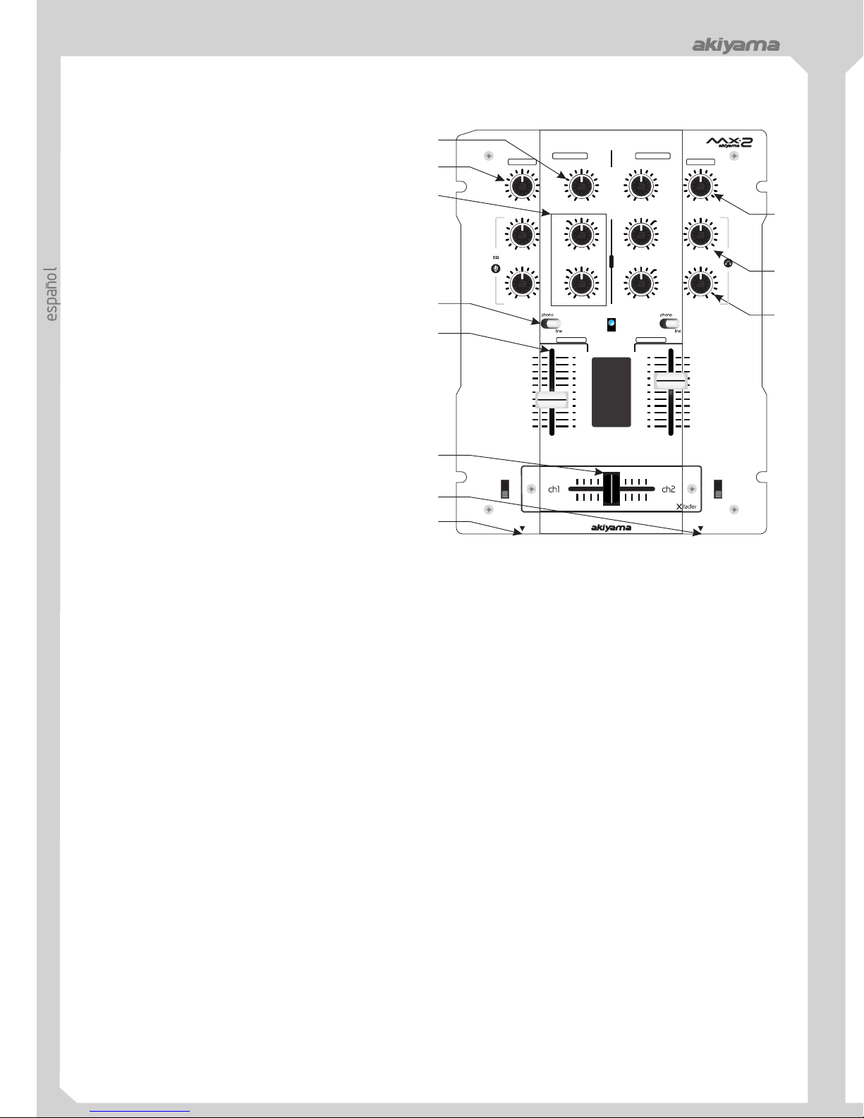
CONTROLES DEL MEZCLADOR
1. Mic Input Gain
2. Treble and Bass EQ
3. Input fader
4. Replaceable Crossfader
5. Mic Input
6. Headphone Input
7. Input toggle switch
8. Channel Cue / Cue Pan
9. Headphone Level
10. Master Fader
11. Channel Gain
frequency levels of the inputchannelsforgood sound.
(channels) in the mix.
between the two input channels. "Hard left" selects
Channel 1. "Hard right" selects Channel 2. With the
crossfader centered, both assigned channelsarelive.
Use the crossfader for fast and seamless segues (fades)
from one selected channel totheother.
Note: The crossfader is user replaceable in case of
failure. Simply unscrew the two large screws which
hold it in place, lift it out and disconnect it’s cable. Re-
attach the new crossfader and screw the mounting plate
back onto the unit -you’rebackin business!
here.
headphones here.
active based on what you have connected to the rear
panel input section (phono/line).
audio to your headphones. Listen here before bringing
up channel faders or movingthecrossfader.
cleaner sound.
Front Panel
Rear Panel
12. Power Switch
13. Power Connector
14. Fader Start
15. Stereo Main Outputs
16. Line Inputs
17. Phono Inputs
18. Grounding lug
here and checkthe voltage levelto match your
country’sstandard.
conjunction with a compatible fader start CD
player. When used with a compatible CD
player, you can use the crossfader to start and
stop the CD player with the slide of the fader.
The fader start switch activates the fader start
feature. When in the ON position, the fader
start allows the fader to return automatically
to preset digital CUE POINTS on your
compatible CD Player.
HiFi VCRs, cassette and reel-to-reel tape decks, DAT machines, laser discs, tuners, even synthesizers or other
mixing consoles.
the high-quality RIAA phono pre-amplifiers. Use this position only for turntables. Line level sources will
overload the sensitive phonopre-ampsand will cause distortion.
ground cable.
1- Control de ganancia de micrófono:
2- Ecualizador:
3- Fader de canal:
4- CrossFader:
5- Conector de Micrófono:
6- Conector de auriculares:
7- Selector de entradas:
8- Preescucha Panorámica:
9- Nivel de volumen de auriculares:
Atención
10- Fader de Master:
11- Ganancia de canal:
Atención:
Permite el
ajuste de la sensibilidad de la señal de entrada del
micrófono.
Se dispone de un control
independiente para frecuencias altas-medidas y bajas.
Por favor advierta que cualquier banda de frecuencia
sobreelevada incrementará elnivel total y hará decrecer
el rango dinámico del equipo. Además, puede elevar el
nivel global de la señalhastallegara la saturación.
Mediante estos controles, usted
determina la parte del nivel global al que un canal
específico contribuye. Por favor advierta que el nivel
final de salida debe ser ajustado mediante el Master.
Además el nivel de los canales puede depender de la
posición del Crossfader.
Dada la condición de los Fader de los
canales, que estén “abiertos”, se podrá combinar la
señal de éstos (acción deCrossfaderofundido).
Para mayor operatividad y agilidad del equipo, el
componente mecánico donde se localiza la función de
Crossfader es reemplazable. Para reemplazar el
Crossfader desaloje los tornillos exteriores y retire la
pieza; desconecte el conector y cambie la pieza. De la
nueva pieza conecte el conector y atorníllela al equipo.
Conecte aquí su micrófono
mediante un conector Jack de1/4depulgada.
Conecte aquí sus
auriculares mediante un conector Jack de 1/4 de
pulgada.
á
dos
Phono (giradiscos con cápsula MM)
Línea (CD y Línea sonelmismotipo de entrada)
Mediante esta función
podrá escuchar una mezcla entre las señales entrantes
del canal 1 y 2. Escuchamos una mezcla estéreo de
ambas señales en función del sentido en que giremos el
botón (8).
Le permite
controlar el volumen en un auricular estéreo conectado
al mezclador. Por favor, asegúresede que la impedancia
del auricularsea como mínimo de 32 Ohmios.Además,
esté prevenido contra auriculares de elevada
impedancia que reducirán el nivel máximo de salida en
auricular. Se recomienda escoger un auricular con una
impedancia no superior a 200 Ohmios.
,s
Determina el nivel total de señal
de salida del mezclador.
Permite el ajuste de la
sensibilidad del canal de entrada en función de las
distintas fuentes.
Tenga siempre la precaución de enchufar
primero el mezclador y a continuación el amplificador
para evitar que el ruidode conexión dañe sus altavoces;
para apagar el equipo, apague primero el amplificador
y a continuación el mezclador.
Mediante la palanca de cada
canal decidimos que fuente reproductora est activa de
las posibles conectadas a cada canal.
Se dispone de 2posiblesselecciones:
e recomienda mantener el volumen al
mínimo antes de comenzar lareproducción.
Es posible realizar unajuste óptico de
MASTER mediante la barra de Led's o picómetro.
Panel frontal
MX-2
MX-2 MX-2
10 10
99
88
77
66
55
44
33
22
11
00
fader
start 1
fader
start 2
on
channel 1channel 2
mic
channel 2channel 1
master
level
mic
12dB
eqeq
gain
high
low
gain
level
level
pan
master
cue
cue
minmin min min
min
ch1
maxmax max max
max
ch2
high high
low low
-26dB-10dB
-10dB
-26dB
-26dB -26dB
12dB12dB
12dB
12dB
12dB
mic heaphones
cue
1
2
3
4
5
6
7
8
11
10
9
1
2
3
4
5
6
7
11
Master Output dB
CUE
Page 5
47
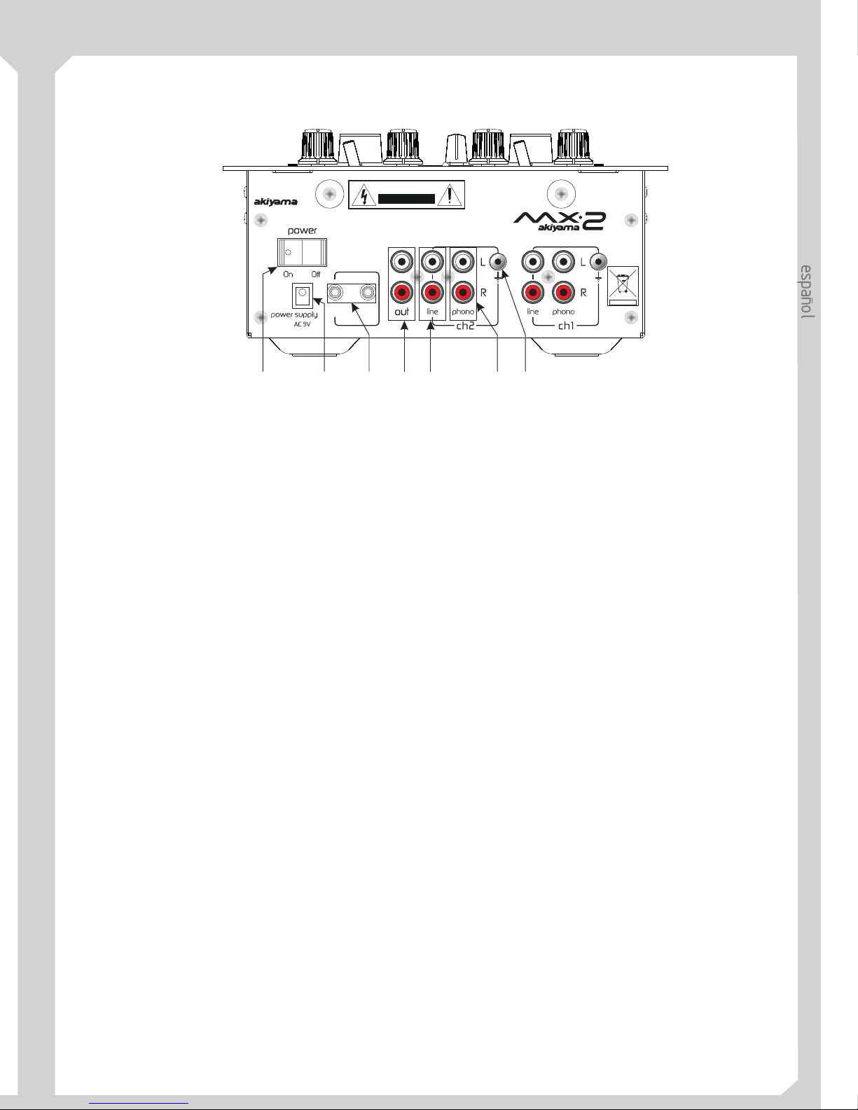
Panel trasero
fader
start 1
fader
start 2
remote
CAUTION
RISK OF ELECTRIC SHOCK
DO NOT OPEN
CAUTION,RISK OFELECTRIC SHOCK, DONOT OPEN.
ATENTION: TO REDUCE RISK OF ELECTRIC SHOCK DO NOT
OPERATE INSIDE THE EQUIPMENT. FOR MAINTENANCE
CONTACTYOURDEALER ORQUALIFIED PERSONNEL.
AKIYAMA. 08191 BARCELONA(SPAIN)
12 13
15
16
1817
14
12- Conector de puesta en marcha:
Atención:
13- Zócalo de conexión a red:
14- Arranque remoto por fader:
15-
16- Entradas de Línea:
17- Entradas Phono (giradiscos):
18- Toma de tierra:
Accionando el
conmutador Power Switch el aparato será puesto en
marcha. Mediante una segunda acción sobre el
conmutador el aparato se apagará. El LED
correspondiente se iluminará cuando el aparato esté en
funcionamiento. Por favor advierta que este LED no se
apagará inmediatamente al desconectar el equipo,
debido a que el condensadordebededescargarseantes.
Tenga siempre la precaución de enchufar
primero el mezclador y a continuación el amplificador
para evitar que el ruidode conexión dañe sus altavoces;
para apagar el equipo, apague primero el amplificador
y a continuación el mezclador.
Conectar el dispositivo
de conexión a redAC a la toma de la pared.Accionando
el conmutador Power Switch el aparato será puesto en
marcha.
Los canales están
dotados de función de arranque de un equipo remoto
mediante el fader del canal al que esté conectado dicho
equipo. Las conexiones son tipoJack3,5.
Esta función nos permite el arranque remoto de un
reproductor de CD o Giradiscos conectado al
mezclador. Para habilitar el arranque remoto mediante
fader (potenciómetro deslizante)deberemos conectar el
reproductor de CD o Giradiscos a uno de los conectores
(14). Una ver realizada esta conexión el proceso de
arranque remoto de un reproductor de CD es el
siguiente:
- Disponga el control fader del canal al que está
conectado el reproductor deCD en laposición0.
- Busque el punto de arranque deseado en el
reproductor de CD y disponga éste en posición Pausa en
este punto (suele llamarseCUEpoint).
- Para comenzar la reproducción del CD eleve la
posición del fader y elCD comenzará la reproducción en
el punto CUE seleccionadoconanterioridad.
En el caso del giradiscos, una vez debidamente
conectado. Al elevar la posición del fader
correspondiente comenzará la reproducción.
Conecte al amplificador.
Normalmente usamos esta salida para conectar a
amplificadores domésticos o amplificadores
profesionales.
Inserte aquí los conectores
RCA de cualquier fuente de señal de línea (CD Player,
MD player,Cassette Player,etc.)
Inserte aquí los
conectores RCA de los giradiscos tipo (MM, moving
magnet). En la actualidad todos los giradiscos para DJ
son del tipo MM.
Los giradiscos disponen de un
cable auxiliar de masa o tierra. Conecte este cable a la
toma de tierra del mezclador, de este modo anulamos
los posibles ruidos de masaotierra(hum).
I
II
III
Salida Master L,R:
CONECTORES DEL MEZCLADOR
NOTA: En lapágina final deeste manual sepresenta un
diagrama de conexiones.
MX-2
Page 6
CARACTERÍSTICAS Y ESPECIFICACIONES
5
4
4
4
4
4
4
4
4
Diseño compacto
Crossfader reemplazable
Entradas: 2 phono, 2 línea, 1 micrófono
Control Gain, Treble y Bass en canales
Salida de cascos potente
Selector Cue Pan (Ch.1-Ch.2)
Indicadores Led de nivel
Fader Start seleccionable (CH.1-CH.2)
Especificaciones
Características
SENSIBILIDAD DE ENTRADA (NIVEL/IMPEDANCIA):
LÍNEA -14dB/47K OHM ±3dB
PHONO -50dB /47K OHM ±3dB
MIC -54dB /6K OHM ±3dB
SALIDA (NIVEL/IMPEDANCIA):
MASTER (RCA) 0dB/47K OHM ±3dB
PHONES (CARGA=32 OHM) -3dB/33 OHM ±3dB
SALIDA MÁXIMA (CARGA=47K, THD=5%)
MASTER (RCA) MAS DE 18dB (8V)
PHONES (CARGA=32 OHM) MAS DE 5dB (1.8V)
BALANCE ENTRE CANALES ENTRE 3dB
RESPUESTA EN FRECUENCIA:
LÍNEA 20-20KHz ±3dB
PHONO 20-20KHz +2, -3dB (RIAA)
MIC 50-20KHz +2/-3dB
RUIDO EN SALIDA (IEC-A WEIGHTED)
LÍNEA MENOS DE -75dB
PHONO MENOS DE -65dB
MIC MENOS DE -55dB
DISTORSIÓN HARMÓNICA:
MASTER OUTPUT
(LOAD=47K OHM) MENOS DE 0.2%
PHONES OUT (LOAD=32 OHM) MENOS DE 0.3%
CROSSTALK (Separación entre canales)
MAS DE 50dB A 1KHz
ENTRECANALESLYR.
ECUALIZADOR:
LOW +9 /-26dB +2 / -3dB A 100Hz
HI +9 /-26dB +2 / -3dB A 10KHz
MIC EQ
LOW +10/-10dB +2 / -3dB A 100Hz
HI +10/-10dB +2 / -3dB A 10KHz
ALIMENTACIÓN AC 9V
DIMENSIONES 228 (A) X 265 (Prof.) X 87 (Al) mm
PESO 2.8Kgs
MX-2
MX-2 MX-2
Page 7

ENGLISH MANUAL
MX-2
Page 8
WARNINGS
CAUTION
RISK OF ELECTRIC SHOCK
DO NOT OPEN
CAUTION: To reduce the risk of electric shock, do not remove any
cover. No user-serviceable parts inside. Refer servicing to qualified
service personnel only.
The lightning flash with arrowhead symbol within the
equilateral triangle is intended to alert the use to the
presence of un-insulated “dangerous voltage” within the
product's enclosure that may be of sufficient magnitude to
constitute a riskofelectric shock.
The exclamation point within the equilateral triangle is
intended to alert the user to the presence of important
operation and maintenance (servicing) instructions in the
literature accompanying thisappliance.
WARNING
TO PREVENT FIRE OR SHOCK HAZARD. DO NOT USE THIS PLUG WITH AN EXTENON CORD, RECEPTACLE
OR OTHER OUTLET UNLESS THE BLADES CAN BE FULLY INSERTED TO PRESENT BLADE EXPOSURE.
TO PREVENT FIRE OR SHOCK HAZARD. DO NOT EXPOSE THIS APPLIANCE TO RAIN OR MOISTURE.
TO PRVENT ELECTRICAL SHOCK, MATCH WIDE BLADE PLUG TO WIDE SLOT FULLY INSERT.
1. Read Instructions All the safety and operatinginstructions
should be read beforethisproductis operated.
2. Retain Instructions. The safety and operating instructions
should be retained forfuturereference.
3. Heed Warnings. All warnings on the appliance and in the
operating instructions should beadheredto.
4. Follow Instructions. All operating and use instructions
should be followed.
5. Water and Moisture. The appliance should not be used
near water - for example, near a bathtub, washbowl, kitchen
sink, laundry tub, in a wet basement, or near a swimming pool,
and the like.
6. Carts and Stands . The appliance should
be used only with a cart or stand that is
recommended by the manufacturer. An
appliance and cart combination should be
moved with care. Quick stops, excessive force,
and uneven surfaces may cause the appliance
and cart combination tooverturn.
7. Wall or Ceiling Mounting. The product should be
mounted to a wall or ceiling only as recommended by the
manufacturer.
8. Heat. The appliance should be situated away from heat
sources such as radiators, heat registers, stoves, or other
appliances (including amplifiers) thatproduceheat.
10. Grounding or Polarization This product may be equipped
with a polarizedalternation-current line plug(a plug having one
blade wider than the other). This plug will fit into the power
outlet only oneway. This is a safetyfeature. If youare unable to
insert the plug fully into the outlet, try reversing the plug. If the
plug should still failtofit,contact your electrician to replaceyour
obsolete outlet. Do not defeat the safety purpose of the
polarized plug.
11. Power-Cord Protection. Power-supply cords should be
routed so that they are not likely to be walked on or pinched by
items placed upon or against them, paying particular attention
to the cord in correspondence of plugs, convenience
receptacles, and the pointwheretheyexit from the appliance.
12. Cleaning - The appliance should be cleaned only as
recommended by the manufacturer. Clean by wiping with a
cloth slightly damp with water. Avoid getting water inside the
appliance.
13. For AC line powered units - Before returning repaired unit
to user, use an ohm-meter to measure from both AC plug
blades to all exposed metallic parts. The resistance should be
more than 100,000 ohms.
14. Non-use Periods.Thepower cord of theappliance should be
unplugged from the outlet when left unused for a long period of
time.
15. Object and Liquid Entry. Care should be taken so that
objects do not fall and liquids are not spilled into the enclosure
through openings.
16. Damage Requiring Service. The appliance should be
serviced by qualified servicepersonnelwhen:
The power-supply cord ortheplughas been damaged; or
Objects have fallen, or liquid has been spilled into the
appliance; or
The appliance has beenexposedtorain; or
The appliance does not appear to operate normally or
exhibits a marked changeinperformance;or
The appliance has been dropped, or the enclosure
damaged.
17. Servicing. The user should not attempt any service to the
appliance beyond that described in the operating instructions. All
other servicing should bereferredtoqualified service personnel.
18. Ventilation Slots and openings in the cabinet are provided
for ventilation and to ensurereliable operation of the productand
to protect it from overheating, and these openings must not be
blocked or covered. The openings should never be blocked by
placing the product on a bed, sofa, rug, or other similar surface.
This product shouldnot be placedin a built-in installationsuch as
a bookcase or rack unless proper ventilation is the
manufacturer's instructions have beenadheredto.
19. Attachments do not use attachments not recommended by
the product manufacturer astheymaycause hazards.
20. Accessories Do not place this product on an unstable cart,
stand, tripod, bracket, or table. The product may fall, causing
serious injury to a child or adult, and serious damage to the
product. Use only with a cart, stand, tripod, bracket, or table
recommended by the manufacturer,or sold withthe product. Any
mounting of the product should follow the manufacturer's
instructions, and should use a mounting accessory
recommended by the manufacturer.
20. Lightning For added protection for this product during a
lightning storm, or when it is left unattended and unused for long
periods of time, unplug it from the wall outlet and disconnect the
antenna or cable system.Thiswill prevent damage to theproduct
due to lightning andpower-linesurges.
22. Replacement Parts When replacement parts are required,
be sure the service technician has used replacement parts
specified by the manufacturer or have the same characteristics
as theoriginal part. Unauthorized substitutions may result in fire,
electric shock, or otherhazards.
23. Safety Check Upon completion of any service or repairs to
this product, ask the service technician to perform safety checks
to determine that theproductisin proper operating condition.
9. Power Sources This product should be operated only
from the type of power source indicated on the rating
label. If you are not sure of the type of power supply to your
home, consult your product dealer or local power
company. For products intended to operate from battery
power,or other sources, refer the operating instructions.
4
4
4
4
4
Panel trasero
12- Conector de puesta en marcha:
Atención:
13- Zócalo de conexión a red:
14- Arranque remoto por fader:
conmutador Power Switch el aparato será puesto en
marcha. Mediante una segunda acción sobre el
conmutador el aparato se apagará. El LED
correspondiente se iluminará cuando el aparato esté en
funcionamiento. Por favor advierta que este LED no se
apagará inmediatamente al desconectar el equipo,
debido a que el condensadordebededescargarseantes.
primero el mezclador y a continuación el amplificador
para evitar que el ruidode conexión dañe sus altavoces;
para apagar el equipo, apague primero el amplificador
y a continuación el mezclador.
de conexión a redAC a la toma de la pared.Accionando
el conmutador Power Switch el aparato será puesto en
marcha.
dotados de función de arranque de un equipo remoto
mediante el fader del canal al que esté conectado dicho
equipo. Las conexiones son tipoJack3,5.
Esta función nos permite el arranque remoto de un
reproductor de CD o Giradiscos conectado al
mezclador. Para habilitar el arranque remoto mediante
fader (potenciómetro deslizante)deberemos conectar el
reproductor de CD o Giradiscos a uno de los conectores
(14). Una ver realizada esta conexión el proceso de
arranque remoto de un reproductor de CD es el
NOTA: En lapágina final deeste manual sepresenta un
diagrama de conexiones.
MX-2
MX-2 MX-2
Page 9
8
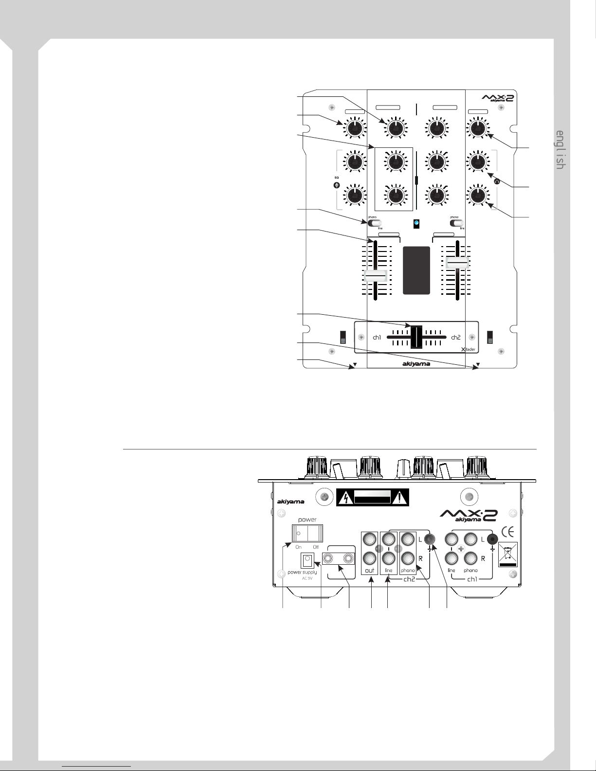
MIXER CONTROLS
10 10
99
88
77
66
55
44
33
22
11
00
fader
start 1
fader
start 2
on
channel 1channel 2
mic
channel 2channel 1
master
level
mic
12dB
eqeq
gain
high
low
gain
level
level
pan
master
cue
cue
minmin min min
min
ch1
maxmax max max
max
ch2
high high
low low
-26dB-10dB
-10dB
-26dB
-26dB -26dB
12dB12dB
12dB
12dB
12dB
mic heaphones
cue
1
2
3
4
5
6
7
8
11
10
9
1
2
3
4
5
6
7
11
1. Mic Input Gain
2. Treble and Bass EQ
3. Input fader
4. Replaceable Crossfader
5. Mic Input
6. Headphone Input
7. Input toggle switch
8. Channel Cue / Cue Pan
9. Headphone Level
10. Master Fader
11. Channel Gain
–Adjustsmicrophoneinput level.
- Adjusts the high and low
frequency levels of the inputchannelsforgood sound.
- Controls individual source levels
(channels) in the mix.
- Achieves clean segues
between the two input channels. "Hard left" selects
Channel 1. "Hard right" selects Channel 2. With the
crossfader centered, both assigned channelsarelive.
Use the crossfader for fast and seamless segues (fades)
from one selected channel totheother.
Note: The crossfader is user replaceable in case of
failure. Simply unscrew the two large screws which
hold it in place, lift it out and disconnect it’s cable. Reattach the new crossfader and screw the mounting plate
back onto the unit -you’rebackin business!
– Insertyour Microphone with ¼” plug in
here.
– Insert in the ¼” plug for your
headphones here.
- Selects which source will be
active based on what you have connected to the rear
panel input section (phono/line).
- Used to preview channel
audio to your headphones. Listen here before bringing
up channel faders or movingthecrossfader.
–Adjustscuevolume.
- Controls the overall outputlevel.
– Adjusts the pre-fader volume for
cleaner sound.
Front Panel
Rear Panel
12. Power Switch
13. Power Connector
14. Fader Start
15. Stereo Main Outputs
16. Line Inputs
17. Phono Inputs
18. Grounding lug
– turns unit off and on.
- Plug inpower adapter
here and checkthe voltage levelto match your
country’sstandard.
– This function works in
conjunction with a compatible fader start CD
player. When used with a compatible CD
player, you can use the crossfader to start and
stop the CD player with the slide of the fader.
The fader start switch activates the fader start
feature. When in the ON position, the fader
start allows the fader to return automatically
to preset digital CUE POINTS on your
compatible CD Player.
- Unbalanced RCA connectors controlled bytheMaster fader.
- Unbalanced RCAjacksfor connecting stereo audio from linelevelsources such as CD players,
HiFi VCRs, cassette and reel-to-reel tape decks, DAT machines, laser discs, tuners, even synthesizers or other
mixing consoles.
– Plug your turntables in here. When these connectors are used, your signal is fed directly to
the high-quality RIAA phono pre-amplifiers. Use this position only for turntables. Line level sources will
overload the sensitive phonopre-ampsand will cause distortion.
- for turntable connection. Always use this connection when using standard turntables with
ground cable.
fader
start 1
fader
start 2
remote
CAUTION
RISK OF ELECTRIC SHOCK
DO NOT OPEN
CAUTION,RISK OFELECTRIC SHOCK, DONOT OPEN.
ATENTION: TO REDUCE RISK OF ELECTRIC SHOCK DO
NOT OPERATE INSIDE THE EQUIPMENT. FOR
MAINTENANCECONTACT YOUR DEALEROR QUALIFIED
PERSONNEL.
AKIYAMA. 08191 BARCELONA(SPAIN)
12 13
15
16
1817
14
MX-2
Master Output dB
CUE
Page 10
9
Es posible que este sea tu primer mezclador, es por ello
que hemos creído oportuna esta introducción donde te
10 minutos...Léeme!
Nomenclatura
Un mezclador esun equipo electrónicoque recibe señal
de distintos reproductores, la mezcla y envía su salida
(Master) a laetapa de amplificación. Esta essu función,
Nivel de la señal dentro del mezclador
Cada mezclador tiene lo que se llama un nivel nominal.
Este es el nivel de señal al que el mezclador trabaja en
óptimas condiciones, evitando ruidos de base y
evitando llegar asaturación (+ sobresaturación en unos
minutos). El nivel de la señal de los distintos
reproductores conectados almezclador debe serparejo.
entrante debemos observar la barra de LEDs mientras
manipulamos el potenciómetro GAIN tal que ésta sólo
se ilumina en rojo esporádicamente.
El nivel de señal entrante se controla con el
potenciómetro GAIN
Saturación
¿Que es la saturación?
Es el deteriorode una señal debido a que su nivel es tan
elevado que el equipo no puede proporcionar voltaje
suficiente para amplificarla sin deteriorarla. Una señal
saturada suena mal.
La señal eléctrica que sale de tu reproductor de CD
pasará primero por el mezclador, después,
posiblemente, por un procesador de efectos, a
continuación por tu amplificador y finalmente por tus
cajas acústicas. En este recorrido“electrónico”pasapor
FEATURES AND SPECIFICATIONS
4
4
4
4
4
4
4
4
Compact design
User replaceable crossfader
2 phono, 2 line, 1 microphone input
Gain, Treble, and Bass Controls on Channels
Powerful stereo headphone output
Cue Pan Selector (Ch.1-Ch.2)
Bright LED Output Indicators
Selectable Fader Start (Ch.1–CH.2)
Specifications
SENSITIVITY OF INPUT (LEVEL/IMPEDANCE):
LINE -14dB/47K OHM ±3dB
PHONO -50dB /47K OHM ±3dB
MIC -54dB /6K OHM ±3dB
OUTPUT (LEVEL/IMPEDANCE):
MASTER (RCA) 0dB/47K OHM ±3dB
PHONES (LOAD=32 OHM) -3dB/33 OHM ±3dB
MAX. OUTPUT (LOAD=47K, THD=5%)
MASTER (RCA) MORE THAN 18dB (8V)
PHONES (LOAD=32 OHM) MORE THAN 5dB (1.8V)
CHANNEL BALANCE WITHIN 3dB
FREQUENCY RESPONSE:
LINE 20-20KHz ±3dB
PHONO 20-20KHz +2, -3dB (RIAA)
MIC 50-20KHz +2/-3dB
OUTPUT NOISE (IEC-A WEIGHTED)
LINE LESS THAN -75dB
PHONO LESS THAN -65dB
MIC LESS THAN -55dB
TOTAL HARMONIC DISTORTION:
MASTER OUTPUT
(LOAD=47K OHM) LESS THAN 0.2%
PHONES OUT (LOAD=32 OHM) LESS THAN 0.3%
CROSSTALK
MORE THAN 50dB AT 1KHz
BETWEEN L AND R CHANNEL.
EQUALIZER:
LOW +9 /-26dB +2 / -3dB AT 100Hz
HI +9 /-26dB +2 / -3dB AT 10KHz
MIC EQ
LOW +10/-10dB +2 / -3dB AT 100Hz
HI +10/-10dB +2 / -3dBAT 10KHz
POWER SOURCE AC 9V
DIMENSIONS 228 (W) X 265 (D) X 87 (H) mm
WEIGHT 2.8Kgs
MX-2
MX-2 MX-2
Gain
min max
Page 11
10
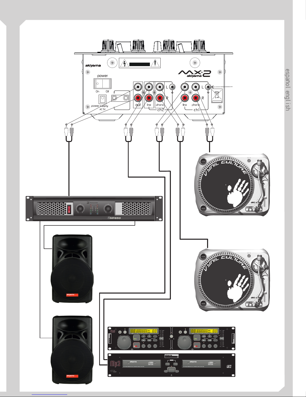
CONEXIONES/CONNECTIONS
fader
start 1
fader
start 2
remote
CAUTION
RISK OF ELECTRIC SHOCK
DO NOT OPEN
CAUTION,RISK OFELECTRIC SHOCK, DONOT OPEN.
ATTENTION: TO REDUCE RISK OF ELECTRIC SHOCK
DO NOT OPERATE INSIDE THE EQUIPMENT. FOR
MAINTENANCE CONTACT YOUR DEALER OR
QUALIFIEDPERSONNEL.
AKIYAMA. 08191 BARCELONA(SPAIN)
Turntables earth connection
Toma de tierra para
giradiscos
POWER AMPLIFIER/ETAPA DE POTENCIA
CD PLAYER/REPRODUCTOR DE CD
TURNTABLE/GIRADISCOS
Up to 2 line level devices can
be connected
Podemos conectar hasta 2
aparatos de nivel de señal de
línea
Up to 2 turntables can be
connected
Podemos conectar hasta 2
giradiscos
R+L R+L R+L R+LR+L
CD PLAYER 1 (L+R)
CD PLAYER 2 (L+R)
0% 0%
scan scan
program program
search search
t
t
s
s
h
h
u
u
t
t
e
e
l
l
single singletime time
o op pe en n
/ /
-12% -12%
+12% +12%
pitch pitch
relay
CD 1 CD 2
+10 +10
loop loop
pitch pitch
jog
/
jog
/
shuttle
/
shuttle
/
CUC
U
CD 1 CD 2
on/of f
CD 2CD 1
STOP
open/close
Digital
output
close close
1 2
track track
i it tc ch hbend bend
shock
memmory
Anti
mp
3
mp
3
mp
3
player
mp
3
player
CDJ-MP
CDJ-MP
CDJ-MP
CLIP
-10dB
-20dB
SIGNAL
PROTECT
ACTIVE
19 19
15 15
12 12
10 10
29 29
8 8
6 6
4 4
2 2
0 0
8
8
CHANNEL 1 CHANNEL 2
dB dB
POWER
MX-2
Page 12

C/ Praga, nº11. P. Cova Solera. 08191. Rub . Tel: 0034935861730. Fax: 0034936996087
info akiyamadj.com / www.akiyamadj.com
Www.akiyamadj.com
í (España)
@
 Loading...