

Page 1

S
S
S
e
e
e
C
C
C
r
v
r
v
r
v
o
o
o
i
i
i
l
l
l
c
c
c
o
o
o
e
e
e
u
u
u
M
M
M
r
r
r
T
T
T
a
a
a
V
V
V
n
n
n
u
u
u
a
a
a
l
l
l
Page 2

2
M
M
M
o
d
e
l
G
r
o
u
p
:
C
T
-
2
o
o
d
d
e
e
l
l
G
G
r
r
o
o
u
u
p
p
:
:
C
C
T
T
-
-
2
2
1
CHASSIS: H704V
MODEL:
1
1
F
F
F
D
D
D
9
9
9
CT-21FD9CP
CT-21FD9M
Model No: CT-21FD9CP_21FD9M
Version 1.0
Page 3

CONTENTS
1. SAFETY INSTRUCTIONS ……………………………………... 4
2. GENERAL INSTRUCTIONS …………………………………… 6
3. SPECIFICATIONS ………………………………………………. 9
4. INSTRUCTION MANUAL ……………………………………….11
5. TROUBLESHOOTING …………………………………………..21
6. BLOCK DIAGRAM ……………………………………………….27
7. THE METHOD OF ADJUSTMENT FOR CHASSIS ………….28
8. IC DESCRIPTION ……………………………………………….. 32
9. EXPLODED VIEW ………………………………………………. 37
10. SCHEMETIC DIAGRAM …………………………………………39
11. PRINTED CIRCUIT BOARD …………………………………… 41
12. REPLACEMENT PARTS LIST …………………………………43
3
Model No: CT-21FD9CP_21FD9M
Version 1.0
Page 4
4
• SAFETY PRECAUTION
WARNING: Service should not be attempted by anyone unfamiliar with the necessary
precaution on this receiver. The following are the necessary precaution to be observed before
servicing.
1. Always discharge the picture tube anode to the CRT conductive coating before
handing the picture tube. The picture tube is highly evacuated and if broken, glass
fragments will be violently expelled. Use shatterproof goggles and keep picture tube
away from the body while handing.
2. When replacing chassis in the cabinet, always be certain that all the protective
devices are put back in place, such as; nonmetallic control knobs, insulating covers,
shields, isolation resistor-capacitor network, etc.
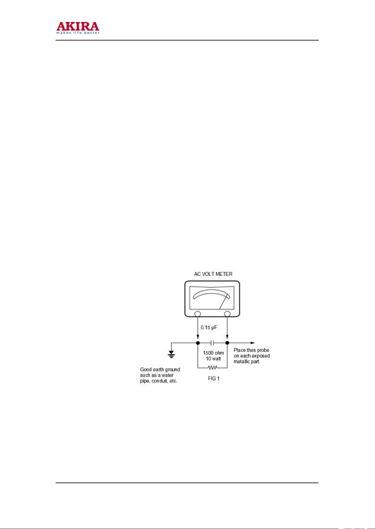
3. Before returning the set to the customer, always perform an AC leakage current
check on the exposed metallic parts of the cabinet, such as antennas, terminals,
screw heads, metal overlays, control shafts etc. To be sure the set is safe to operate
without danger of electrical shock. Plug the AC line cord directly onto an 110/220V
AC outlet. Use an AC voltmeter having 500 ohms per volt or more sensitivity in the
following manner. Connect a 1500 ohm 10-watt resistor, paralleled by a 0.15 µF, AC
type capacitor, between a known good earth ground (water pipe, conduit etc.) and the
exposed metallic parts, one at a time. Measure the AC voltage across the
combination of 1500-ohm resistor and 0.15-µF capacitor. Reverse the AC plug at the
AC outlet and repeat AC voltage measurements for each exposed metallic part.
Voltage measured must not exceed 0.3 volts RMS. This corresponds to 0.2 milliamp.
AC Any value exceeding this limit constitutes a potential shock hazard and must be
corrected immediately.
Model No: CT-21FD9CP_21FD9M
Version 1.0
Page 5

5
1. SAFETY INSTRUCTIONS
1-1 PRODUCT SAFETY NOTICE
Many electrical and mechanical parts in this chassis have special safety-related
characteristics.
These characteristics are often passed unnoticed by a visual inspection and the protection
afforded by them cannot necessarily be obtained by using replacement components rated for
higher voltage, wattage, etc. Replacement parts which have these special safety
characteristics are Identified in this manual and its,
Supplements: Electrical components having such features are identified by shading on the
schematic diagram and the part list. Before replacing any of these components, read the parts
list in this manual carefully. The use of substitute replacement parts which do not have
same safety characteristics as specified in the parts list may create shock, fire or other
hazards.
1-2 SERVICE NOTES
1. When replacing parts or circuit boards, clamp the lead wires to terminals before
soldering.
2. When replacing a high wattage resistor (metal oxide film resistor in the circuit. board)
keep the resistor min 1 /2inch away from the circuit board.
3. Keep wires away from high voltage or high temperature components.
Model No: CT-21FD9CP_21FD9M
Version 1.0
Page 6
6
2. GENERAL INSTRUCTIONS
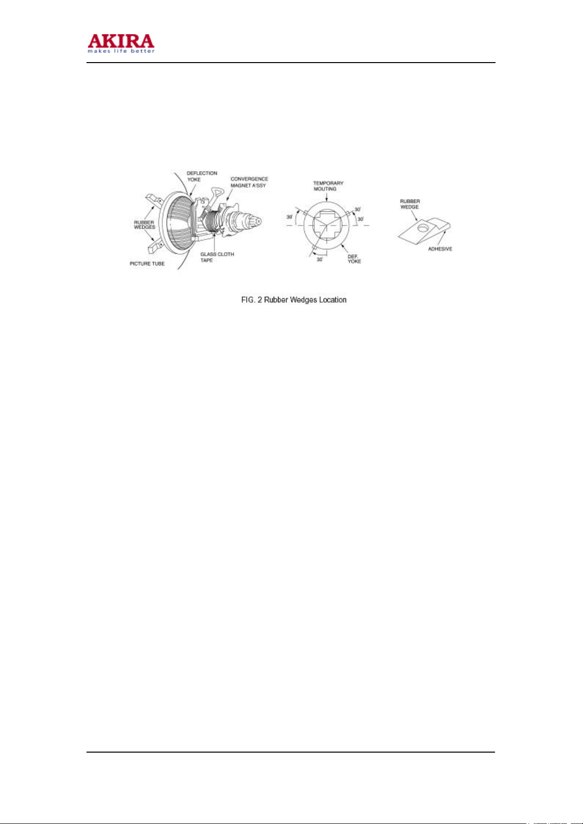
2-1 CONVERGENCE MAGNET ASSEMBLY POSITIONING
Convergence magnet assembly and rubber wedges need mechanical positioning following
figure 2.
2-2 COLOR-PURITY-ADJUSTMENT
NOTE: Before attempting any purity adjustments, the receiver should be operated for at least
15 minutes.
1. Demagnetize the picture tube and cabinet by using a degaussing coil.
2. Turn the CONTRAST and BRIGHTNESS controls to maximum.
3. Adjust RED and BLUE BIA, 5 controls to provide only a green rather.
4. Loosen the clamp screw holding the yoke, and slide the yoke backward to provide
vertical green belt (zone) in the picture screen.
5. Remote the Rubber Wedges.
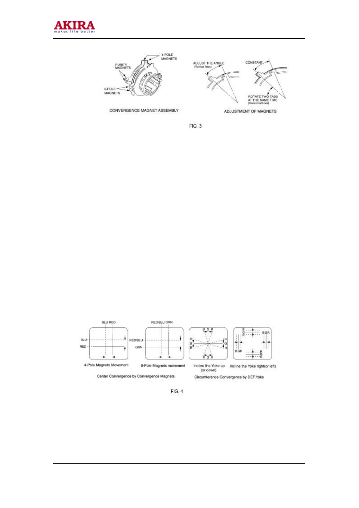
6. Rotate and spread the tabs of the purity magnet (See figure 3) around the neck of the
picture tube until the green belt is in the center of the screen. At the same time,
center the raster vertically.
7. Move the yoke slowly forward until a uniform green screen is obtained. Tighten the
clamp screw of the yoke temporarily.
8. Check the purity of the red and blue raster by adjusting the BIAS controls.
9. Obtain a white raster, referring to “CRT GRAY SCALE ADJUSTMENT”.
10. Proceed with convergence adjustment.
Model No: CT-21FD9CP_21FD9M
Version 1.0
Page 7
7
2-3 CONVERGENCE ADJUSTMENTS
NOTE: Before attempting any convergence adjustment, the receiver should be operated for at
least 15 minutes.
2-3-1 CENTER CONVERGENCE ADJUSTMENTS
1. Receive a crosshatch pattern with a color bar signal generator.
2. Adjust the BRIGHTNESS and CONTRAST controls for a well-defined pattern.
3. Adjust two tabs of the 4-pole Magnets to change the angle between them (See figure
(3) and superimpose red and blue vertical lines in the center area of the picture
screen.
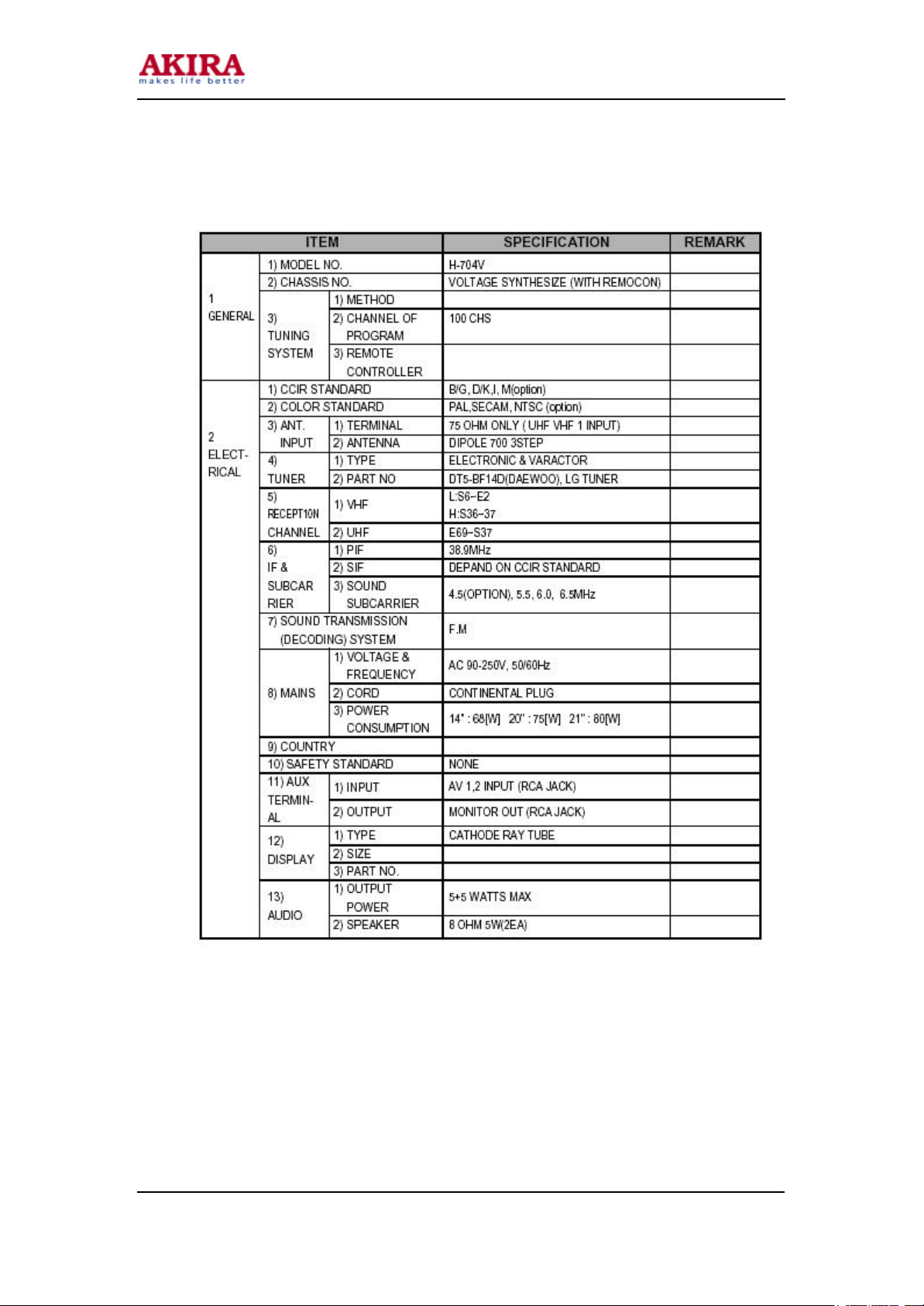
4. Turn both tabs at the same time keep in their angles constant to superimpose red and
blue horizontal lines at the center of the screen. (See figure 4).
5. Adjust two tabs of 6-Pole Magnets to superimpose red/blue line with green one.
Adjusting the angle affects the vertical lines and rotating both magnets affects the
horizontal lines.
6. Repeat adjustment 3, 4, 5 Keeping in mind red. green and blue movement, because
4-Pole Magnets and 6-Pole Magnets interact and make dot movement complex.
Model No: CT-21FD9CP_21FD9M
Version 1.0
Page 8

2-3-2 CONVERGENCE ADJUSTMENTS
NOTE: This adjustment requires Rubber Wedge Kit.
1. Loosen the clamping screw of deflection yoke to allow the yoke to tiIt.
2. Place a wedge as shown in figure (2) temporarily.
(Do not remove cover paper on adhesive part of the wedge.)
3. Tilt the front of the deflection yoke up or down to obtain better convergence in
circumference (See figure 4) Push the mounted wedge into the space between
picture tube arid the yoke to hold the yoke temporarily.
4. Place other wedge into bottom space arid remove the cover paper to stick.
5. Tilt the front of the yoke right or left to obtain better convergence in circumference
(See figure 4.)
6. Hold the yoke position arid put another wedge in upper space, remove cover paper
and stick the wedges, recheck overall convergence.
7. Detach the temporarily mounted wedge and put it in another upper space.
Stick 2 on picture tube to fix the yoke.
8. After placing three wedges, recheck overall convergence.
Tighten the screw firmly to hold the yoke tightly in place.
9. Stick 3 adhesive tapes on wedges as shown in figure 2.
Model No: CT-21FD9CP_21FD9M
Version 1.0
8
Page 9
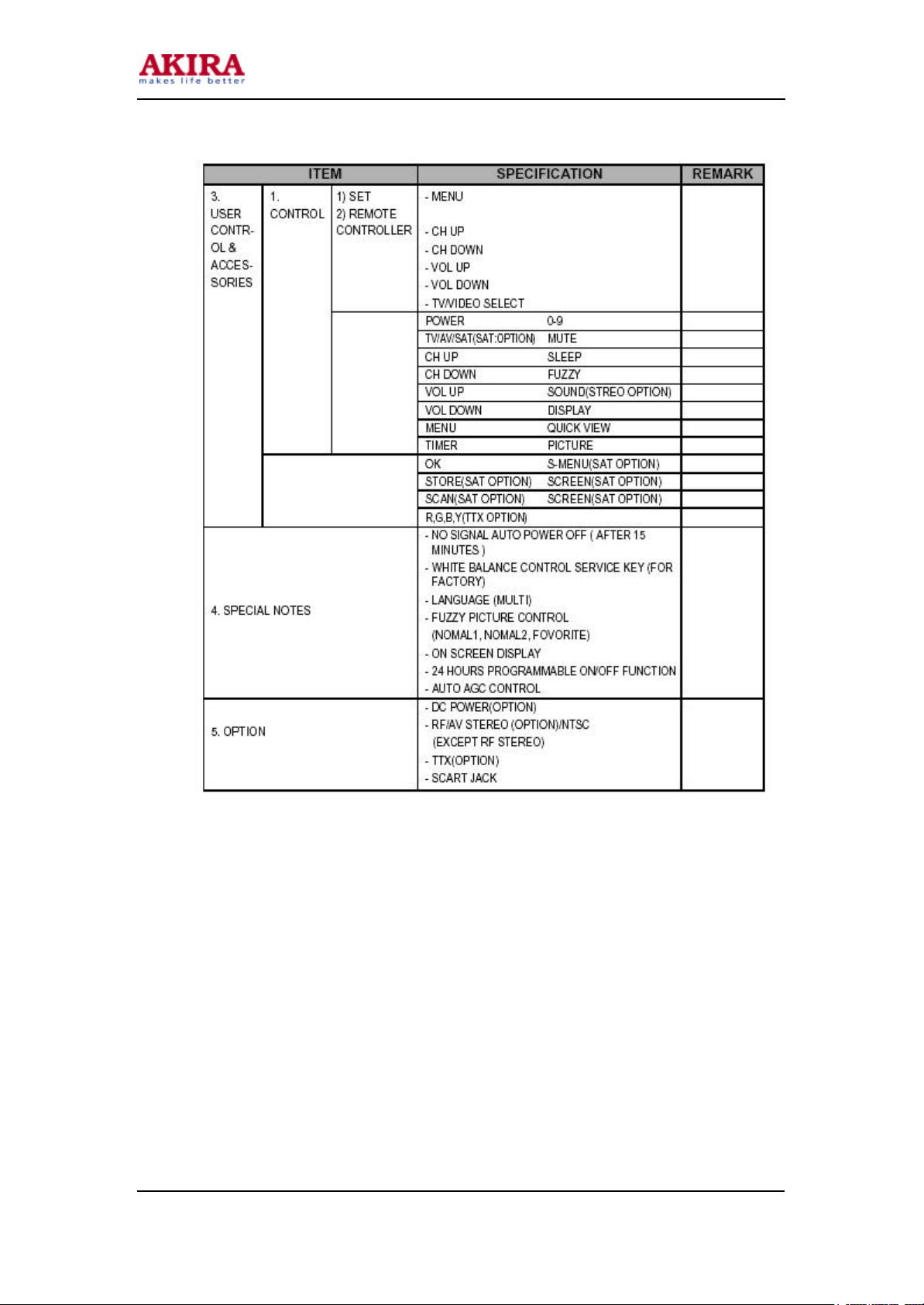
3. SPECIFICATIONS
9
Model No: CT-21FD9CP_21FD9M
Version 1.0
Page 10
10
Model No: CT-21FD9CP_21FD9M
Version 1.0
Page 11
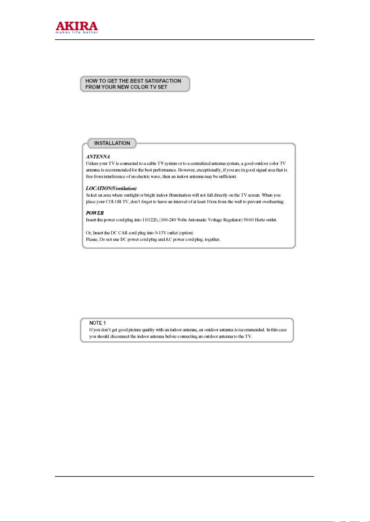
4. INSTRUCTION MANUAL
To get the best satisfaction with your new COLOR TV SET, please read carefully and follow the
instruction in this guide.
We recommend that you read it before turning on your TV for the first time.
11
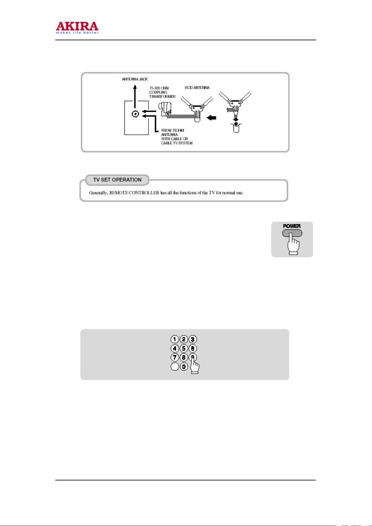
4-1. VHF ANTENNA or CABLE HOOK UP
At first, insert the lead of rod antenna into antenna adapter.
And connect antenna adapter to tuner jack. This antenna will provide an excellent picture in most areas.
For the best picture quality, adjust the length and position of antenna.
Model No: CT-21FD9CP_21FD9M
Version 1.0
Page 12
• MAKE REFERENCE TO THE BELOW THE PICTURE
4-2. TO TURN ON/OFF THE TV SET
4-2-1 To turn on the TV, press MAIN POWER BUTTON on the front of TV, then
press any BUTTON on the PANEL or REMOTE CONTROLLER.
4-2-2 To turn off the TV, press POWER BUTTON on the PANEL or REMOTE
CONTROLLER.
4-3. TO SELECT CHANNEL
You can select the channels with CHANNEL NUMBER buttons or CHANNEL
UP/DOWN button.
4-3-1. TO SELECT CHANNEL DIRECTLY
Press the channel number you want with the number buttons. You can select 0~99 channels.
12
Model No: CT-21FD9CP_21FD9M
Version 1.0
Page 13
13
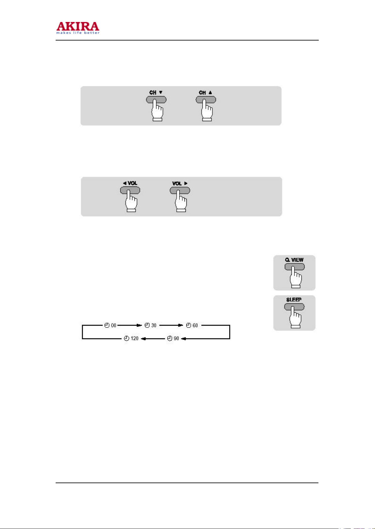
4-3-2. TO SCAN THROUGH CHANNELS
Press the CH UP/DOWN buttons on the PANEL or REMOTE CONTROLLER to find the channel you
want to see.
4-4. TO ADJUST VOLUME
To increase or decrease the volume, press the VOLUME UP/DOWN buttons on the PANEL or
REMOTE CONTROLLER.
4-5 OTHER FUNCTIONS
4-5-1 QUICK VIEW FUNCTION
If you want to go back to the previously viewed channel, press the QUICK VIEW
button.
4-5-2 SLEEP FUNCTION
Press the SLEEP button to set the timer from 30 to 120 minutes. Each time you
press the SLEEP button, changes of time as follows:
Model No: CT-21FD9CP_21FD9M
Version 1.0
Page 14
14
Your TV will be turned off automatically after the set time.
The initial state of SLEEP mode is “ 00”, and the SLEEP FUNCTION does not operate in this state.
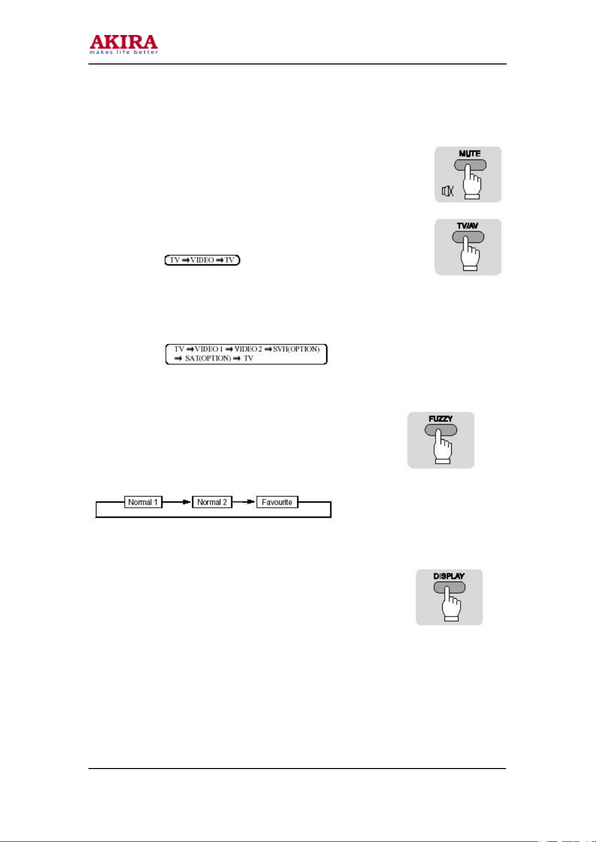
4-5-3 MUTE FUNCTION
MUTE button makes the sound off and displays an icon on the right top of the
screen. Press the MUTE button again or press the VOL UP/DOWN buttons to
restore the sound.
4-5-4 TV/AV BUTTON FUNCTION
You can select TV and VIDEO mode.
To select VIDEO mode, press TV/AV button. The icon below will appear on
the right top of screen.
* STEREO MODEL (OPTION)
You can select TV, VIDEO 1 and VIDEO 2 mode.
To select VIDEO 1 mode, press TV/AV button once, and press twice for Video 2 mode. The icon
below will appear on the right top of the screen.
4-5-5 FUZZY FUNCTION
Users can select a combination of picture control. That includes a
combination of contrast, brightness, sharpness, color and tint.
These combinations are classified as three steps, Normal 1, Normal 2,
Favourite.
Each step will be selected by pressing FUZZY button on REMOTE
CONTROLLER.
4-5-6 DISPLAY FUNCTION
Press the DISPLAY button to see the current time and channel on the screen.
It lasts for four seconds. However, you can press again the DISPLAY button
to make the display disappear instantly.
Time display of this mode indicates the state of clock memory of TIMER of
MENU FUNCTION.
Model No: CT-21FD9CP_21FD9M
Version 1.0
Page 15
15
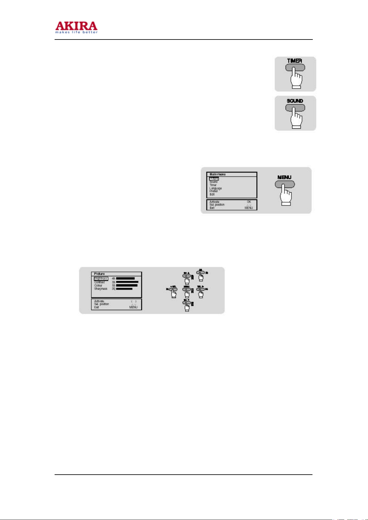
4-5-7. Timer FUNCTION
You can see the current time.
4-5-8. SOUND FUNCTION (STEREO MODEL ONLY)
You can select MONO, STEREO and DUAL 1, DUAL 2 by press the SOUND
button.
4-5-9. OK/DG BUTTON (DC POWER INPUT MODEL ONLY)
DC POWER INPUT MODEL BELOW FUNCTION ITEM ADD.
When the blue parts appear, you can clear the blue parts by press the OK key, but
you can press the OK button just one time during the one minute.
4-6 MENU FUNCTION
If you press the MENU button, six items will
appear on the screen as following.
Press again the MENU button. Then the display
will return to the original screen.
4-6-1. PICTURE
1) Press Menu
2) Press CH UP/DOWN to select PICTURE item, and press O.K
3) Then, four items will appear as following on the screen.
4) Press CH UP/DOWN to select the item you want to adjust.
5) And press VOL UP/DOWN to adjust the item’s value.
6) To adjust other items, repeat step 4 and 5.
7) Press MENU to return to the MENU screen.
Model No: CT-21FD9CP_21FD9M
Version 1.0
Page 16

16
• TINT item appears only when TV set receives the NTSC (play back only) signal.
4-6-2. SOUND (STEREO MODEL ONLY)
1) Press Menu
2) Press CH UP/DOWN to select SOUND item, and press O.K
3) Then, seven items appear as following on the screen.
4) Press CH UP/DOWN to select the item you want to adjust.
5) And press VOL UP/DOWN to adjust the item’s value.
6) To adjust other items, repeat steps 4 and 5.
7) Press MENU to return to the MENU screen.
• AVC : Press VOL. UP/DOWN, then OSD changes from OFF to ON.
You can hear different sound of many broadcasting stations as regular valued sound through this
function.
• Equalizer: Higher resolution is possible in a gain step of about
1/8 dB. With positive equalizer settings, internal clipping may
occur even with overall volume less than 0 dB. This will lead
to a clipped output signal. Therefore, it is not recommended to
set equalizer bands to a value that, in conjunction with volume,
would result in an overall positive gain.
• Audio in (Sound L, R divide mode): When you use the audio
out, you selected STEREO or MONO mode STEREO mode:
audio out divided L, R
• MONO mode: Audio out L (You must hear sound L)
Model No: CT-21FD9CP_21FD9M
Version 1.0
Page 17

17
4-6-3. TIMER
1) Press Menu
2) Press CH UP/DOWN to select TIMER item, and press OK button.
3) Then, five items appear as following on the screen.
4) Press CH DOWN to select the item you want to change.
5) Press OK to change the item’s time value.
6) Press the 0-9 buttons.
7) And press OK to set the time, you changed.
8) To change other items, repeat steps from 4 to 7.
9) Press MENU to return to the MENU screen.
4-6-4. LANGUAGE
* Select your language
1) Press Menu
2) Press CH UP/DOWN to select Language item, and press O.K
3) Then, nine languages appear as following on the screen.
4) Press CH UP/DOWN to select the language you want to use.
5) To change to other languages, repeat step 4.
6) Press MENU to return to the MENU screen.
Model No: CT-21FD9CP_21FD9M
Version 1.0
Page 18

18
4-6-5. PRESET
1) Press Menu
2) Press CH UP/DOWN to select PRESET item, and press O.K
3) Then, items will appear as following on the screen.
4) Press VOL UP/DOWN to select the item you want to change.
5) Press CH UP/DOWN to change the item’s value.
6) To change other items, repeat step 4 and 5.
7) Press MENU to return to the MENU screen.
4-6-6. Edit
* Edit channel (Memory Channel or Skip Channel)
1) Press Menu
2) Press CH UP/DOWN to select Edit item, and press O.K
3) Then, channels appear as following on the screen.
4) Press CH UP/DOWN to select the channel you want to change.
5) And press Yellow button to skip (YES: skip channel, NO: Memory channel).
6) To skip other channels, repeat step 4 and 5.
7) Press MENU to return to the MENU screen.
• To change channel memory
1. Delete
To delete a channel from the memory, press the green button, and after a few seconds the selected
channel will be deleted from the list, and sent to the end of the list. The blank is automatically filled
with the rest of channels in order.
2. Move
1) To move a memory channel to the other channel, press RED button. Then you can see the
color is changed from green to yellow on the screen.
2) Select the other channel on the screen that you want to change by using VOL.UP/DOWN
and CH. UP/DOWN
3) Press RED button on the REMOTE CONTROLLER to move, and then you can see the
changed channel on the screen.
Model No: CT-21FD9CP_21FD9M
Version 1.0
Page 19

19
1) TV/TTX
This is toggle key, TV TELETEXT
When called in TV mode, this function activated TELETEXT
Initially page 100 of teletext will be displayed in the screen, unless at an earlier exit from TELETEXT
(at the same program), another page was requested in the page memory.
When called in TELETEXT sub mode, this command is interpreted as a rest
2) PAGE UP/DOWN
Page number is changed by “PAGE UP” or “PAGE DOWN” button or direct button (0-9).
3) INDEX
Press this key to select index page directly in FLOT and TV program in TOP mode.
4) SIZE
This is a toggle function between 3 different sizes.
Press “SIZE” button to expand the TOP half of the display.
Press again to expand the BOTTOM half of the display.
Press again to return the display to normal size.
5) SUB PAGE ACCESS
First, select the TELETEXT alarm page or TELETEXT page containing sub pages.
Press the “SUB” key, and then four asterisks (“****”) will be displayed on the screen. Now enter the
sub page number required using keys “0-9” on the transmitter.
Press this key again to return to initial status.
6) REVEAL
Press “REVEAL” key to reveal hidden words e.q. quiz pages will hide the answers.
Press the key again to make hidden words disappear.
7) HOLD
When TELETEXT information exceeds more than one page, the display changes automatically to the
next page. In rolling sub pages, press “HOLD” button to hold the wanted display sub page.
And press the next button to stop the hold.
8) MIX
Press “MIX” button to superimpose TELETEXT picture into TV display.
Press this button again, and then the screen goes back to TELETEXT mode.
9) CANCEL
When searching for a TELETEXT page, the TV display can be viewed by pressing “CANCEL” key.
Once the page has been found, the page number will be displayed.
Model No: CT-21FD9CP_21FD9M
Version 1.0
Page 20

20
10) RED, GRE, YEL, CYN KEYS
These four keys are coloured-cord to correspond to the differently coloured subjects in “TTX” mode.
* press the menu
Adjust the volume and contrast in the MENU function
Model No: CT-21FD9CP_21FD9M
Version 1.0
Page 21

21
5. TROUBLESHOOTING
5-1. NO POWER (NOT WORKING SMPS)
Model No: CT-21FD9CP_21FD9M
Version 1.0
Page 22

22
5-2. NO RASTER & PICTURE
Model No: CT-21FD9CP_21FD9M
Version 1.0
Page 23

23
5-3. NO VERTICAL DEFLECTION
5-4. NO TELETEXT
Model No: CT-21FD9CP_21FD9M
Version 1.0
Page 24

24
5-5. NO SOUND (STEREO)
Model No: CT-21FD9CP_21FD9M
Version 1.0
Page 25

25
5-6. DON’T CATCH CHANNEL
Model No: CT-21FD9CP_21FD9M
Version 1.0
Page 26

26
5-7. NO SOUND (MONO)
Model No: CT-21FD9CP_21FD9M
Version 1.0
Page 27

27
6. BLOCK DIAGRAM
Model No: CT-21FD9CP_21FD9M
Version 1.0
Page 28

28
7. THE METHOD OF ADJUSTMENT FOR CHASSIS
FLOW CHART TO ADJUST IN PRODUCT LINE
*. HEAT RUN (AUTO POWER ON MODE): FACTORY KEY
- It need in assembly line during heat run that protect to auto power off after no signal 15
minutes and auto power on for input power of sets on/off by line condition which sometimes
line power connection of palette with main power line would be badly contacted by shaking
during the sets through on assembly lines.
- Heat run function is operated by pressing the f4 key.
- To cancel this function press the power key (on/off.)
- It must be canceled before final output.
Model No: CT-21FD9CP_21FD9M
Version 1.0
Page 29

29
7-1-1. V-SIZE ADJUSTMENT.
- Select the V-SIZE by pressing CH UP/DOWN key
- Adjust the V-SIZE by pressing VOL UP/DOWN key for approximately one-half inch over
scan at top and bottom of picture screen.
7-1-2. V-CENTER ADJUSTMENT.
- Select the V-CENTER by pressing CH UP/DOWN key.
- Adjust V-CENTER so that the vertical center of the picture may be coincident with the
mechanical center of CRT.
7-1-3. H-CENTER ADJUSTMENT.
- Select the H-CENTER by pressing CH UP/DOWN key.
- Adjust the H-CENTER by pressing VOL UP/DOWN key to be agreed with screen center and
mechanical center.
7-1-4. V-LIN ADJUSTMENT.
- Adjust V-LIN by pressing VOL UP/DOWN key.
7-1. V-SIZE / V-CENTER / H-CENTER (F2)
- Receive the video no signal.
- Select the SERVICE mode by pressing CH UP/DOWN key.
- Make the horizontal line by pressing VOL UP/DOWN key.
- Adjust the SCREEN, till horizontal line is just disappeared.
7-2. SCREEN (SERVICE) ADJUSTMENT (F3)
- Receive a black and white pattern or white balance adjusting pattern.
- Before attempting white balance adjustment, the receiver should be operating for at least
15minites.
- Check the all of position to the reference value (nominal center)
- The reference color of the measurement equipment set to G.
- Adjust the CUTOFF G, CUTOFF R, and CUTOFF B at bias mode.
- Adjust the R DRV, B DRV at drive mode.
7-3. WHITE BALANCE ADJUSTMENT (F3)
- Change Mode to VIDEO NO SIGNAL
- Select the NORMAL1 mode in the fuzzy key.
- Select the SUB BRIGHT mode by pressing CH UP/DOWN key in FACTORY2 mode.
- Adjust the SUB BRIGHT value till disappeared to back screen by pressing VOL UP/DOWN.
Model No: CT-21FD9CP_21FD9M
Version 1.0
Page 30

30
7-4. SUB BRIGHT ADJUSTMENT (2)
- Receive the RF color bar signal.
Select the AFT mode, and then press the vol up/down key
Select the OK
7-5. AFT ADJUSTMENT (F1 key)
- Receive the RF color bar signal.
- Strength of input signal control 67dBu.
- Select the AGC POINT mode, and then adjust an AGC POINT to 2.0
- Select the AGC AUTO mode, and then press the vol up/down key
- AGC is arranged automatically
- Confirmation of the strong signal.
7-6. AGC ADJUSTMENT (F1 key)
- It be cleared all user control to initial for all output sets will be same user control condition.
- It need after final inspection.
* (then power on auto tuning automatically)
* CHECK SUM (password: remocon key: display --> mute sleep --> fuzzy --> timer
To memory MASTER ROM (MULTI EEPROM MEMORY).
Adjust the value check sum “NG” by vol up/down
* TO adjust “OPTION MENU”
Press MENU button from factory key
After adjusting an option what you want, press MENU to end “OPTION MENU”
7-7. USER RESET (F2)
EX)
Model No: CT-21FD9CP_21FD9M
Version 1.0
Page 31

31
LANGUAGE (TTX OPTION)
Select the Character set mode, (LANGUAGE)
Model No: CT-21FD9CP_21FD9M
Version 1.0
Page 32

32
8. IC DESCRIPTION
8-1. SDA555XFL
Model No: CT-21FD9CP_21FD9M
Version 1.0
Page 33

33
8-2. POWER IC (I801): STR-G6653
• Function of Terminal
• Other Functions
Model No: CT-21FD9CP_21FD9M
Version 1.0
Page 34

34
8-3. SOUND AMP IC (I603, I604): TDA1905
8-4. VERTICAL IC (I301): LA7841K
Model No: CT-21FD9CP_21FD9M
Version 1.0
Page 35

35
8-5. MAIN IC (I102): NN5198N
Model No: CT-21FD9CP_21FD9M
Version 1.0
Page 36

36
8-6. STZRZO IC (I602)
Model No: CT-21FD9CP_21FD9M
Version 1.0
Page 37

37
9. EXPLODED VIEW
Model No: CT-21FD9CP_21FD9M
Version 1.0
Page 38

38
Model No: CT-21FD9CP_21FD9M
Version 1.0
Page 39

39
10. SCHEMETIC DIAGRAM
Model No: CT-21FD9CP_21FD9M
Version 1.0
Page 40

40
Model No: CT-21FD9CP_21FD9M
Version 1.0
Page 41

41
11. PRINTED CIRCUIT BOARD
Model No: CT-21FD9CP_21FD9M
Version 1.0
Page 42

42
Model No: CT-21FD9CP_21FD9M
Version 1.0
Page 43

43
12. REPLACEMENT PARTS LIST
Model No: CT-21FD9CP_21FD9M
Version 1.0
Page 44

44
Model No: CT-21FD9CP_21FD9M
Version 1.0
Page 45

45
Model No: CT-21FD9CP_21FD9M
Version 1.0
Page 46

46
Model No: CT-21FD9CP_21FD9M
Version 1.0
Page 47

47
Model No: CT-21FD9CP_21FD9M
Version 1.0
Page 48

48
Model No: CT-21FD9CP_21FD9M
Version 1.0
Page 49

49
Model No: CT-21FD9CP_21FD9M
Version 1.0
Page 50

50
Model No: CT-21FD9CP_21FD9M
Version 1.0
Page 51

51
Model No: CT-21FD9CP_21FD9M
Version 1.0
Page 52

52
Model No: CT-21FD9CP_21FD9M
Version 1.0
 Loading...