

Page 1
User Manual
Please read before using the equipment!
CS 5
Conference System
Page 2

Table of Contents
Page
Symbols Used ........................................................................................................................................................................4
Safety and Environment.........................................................................................................................................................5
FCC Statement .........................................................................................................................................................................
Section 1: General..................................................................................................................................................................6
Section 2: Notes on Wiring and System Examples.................................................................................................................7
2.1 Notes on Wiring and System Configuration....................................................................................................................7
2.2 System Examples........................................................................................................................................................8
2.2.1 Simple Discussion System ..................................................................................................................................8
2.2.2 Computer-controlled Discussion System ..............................................................................................................9
2.2.3 Infrared Interpretation System ...........................................................................................................................10
2.2.4 Large Conference System with Interpretation Booths ..........................................................................................11
Section 3: CS5 BU Base Unit................................................................................................................................................13
3.1 General.....................................................................................................................................................................13
3.2 Front Panel ...............................................................................................................................................................13
3.3 Rear Panel................................................................................................................................................................14
3.4 Setting Up the Base Unit ............................................................................................................................................15
3.4.1 Block Diagram .................................................................................................................................................15
3.4.2 Configuring the Dip Switches ............................................................................................................................16
3.4.3 Selecting NOM Limitation/Interpretation Channels ..............................................................................................16
3.4.4 Powering Up ....................................................................................................................................................17
3.4.5 Setting Levels ..................................................................................................................................................17
3.4.6 Selecting NOM Limitation/Interpretation Channels ..............................................................................................18
Section 4: CS5 DU Delegate Station.....................................................................................................................................19
4.1 General.....................................................................................................................................................................19
4.2 Controls, Inputs and Outputs......................................................................................................................................19
4.3 Setting Up.................................................................................................................................................................20
4.3.1 Making Connections.........................................................................................................................................20
4.3.2 Selecting Operating Modes ...............................................................................................................................20
Section 5: CS5 VU Voting/Chairperson Station.....................................................................................................................22
5.1 General.....................................................................................................................................................................22
5.2 Control Panel, Inputs and Outputs...............................................................................................................................22
5.3 Setting Up.................................................................................................................................................................24
5.3.1 Making Connections.........................................................................................................................................24
5.3.2 Selecting Operating Modes ...............................................................................................................................24
5.3.3 DELEGATE Mode..............................................................................................................................................25
5.3.4 PRESIDENT Mode.............................................................................................................................................26
5.4 Voting/Polling............................................................................................................................................................27
5.4.1 Controlling a Ballot or Opinion Poll (PRESIDENT Mode)........................................................................................27
5.4.2 Voting in DELEGATE Mode.................................................................................................................................28
5.5 Chip Card Identification..............................................................................................................................................29
CS 5 User Manual
- 2 -
Page 3

Table of Contents
Page
Section 6: CS 5 IU Interpreter Station.............................................................................................................................30
6.1 General.....................................................................................................................................................................30
6.2 Control Panel, Inputs and Outputs...............................................................................................................................30
6.3 Setting Up.................................................................................................................................................................31
6.3.1 Making Connections.................................................................................................................................................31
6.3.2 Selecting Station Addresses..............................................................................................................................32
6.3.3 Selecting Target Language Channels.........................................................................................................................32
6.3.4 List of Available Language Names .....................................................................................................................33
6.3.5 Selecting the Microphone Type ..........................................................................................................................33
6.4 Using the Interpreter Station.......................................................................................................................................34
Section 7: Infrared Transmission System.............................................................................................................................36
7.1 CS 5 IRT 1 and CS 5 IRT 2 Infrared Radiators..............................................................................................................36
7.1.1 General............................................................................................................................................................36
7.1.2 Placement .......................................................................................................................................................36
7.1.3 Mounting .........................................................................................................................................................37
7.1.4 Connections.....................................................................................................................................................37
7.2 CS 5 IRR 7 Infrared Receiver......................................................................................................................................38
7.2.1 General............................................................................................................................................................38
7.2.2 Using the Infrared Receiver ...............................................................................................................................39
7.2.3 Replacing Batteries...........................................................................................................................................39
7.3 CS 5 CU 50 Charger/Storage Case.............................................................................................................................40
7.3.1 General............................................................................................................................................................40
7.3.2 Charging Batteries............................................................................................................................................40
7.3.3 Battery Care.....................................................................................................................................................41
Section 8: System Components ...........................................................................................................................................42
Section 9: Specifications .....................................................................................................................................................43
9.1 CS 5 BU....................................................................................................................................................................43
9.1.1 General............................................................................................................................................................43
9.1.2 Connector Pinouts............................................................................................................................................44
9.2 CS 5 DU/VU ..............................................................................................................................................................46
9.2.1 General............................................................................................................................................................46
9.2.2 Connector Pinouts............................................................................................................................................46
9.3 CS 5 IU.....................................................................................................................................................................47
9.3.1 General............................................................................................................................................................47
9.3.2 Connector Pinouts............................................................................................................................................47
9.4 CS 5 PS 12...............................................................................................................................................................48
9.5 CS 5 IRT 1 and CS 5 IRT 2.........................................................................................................................................49
9.6 CS 5 IRR 7................................................................................................................................................................49
9.7 CS 5 CU 50...............................................................................................................................................................50
9.8 Conformity................................................................................................................................................................50
CS 5 User Manual
- 3 -
Page 4

Symbols Used
The lightning flash with arrowpoint in an equilateral triangle means that there are dangerous voltages present within
the equipment.
The exclamation point in an equilateral triangle on the equipment indicates that it is necessary for the user to refer to
the User Manual or Quickstart Guide.
In the User Manual and Quickstart Guide, this symbol marks instructions that the user must follow to ensure safe operation of the equipment.
The "
" symbol marks important notes, hints, or explanations that make it easier to use the equipment.
Ъ
!
CS 5 User Manual
- 4 -
Page 5

Safety and Environment
Safety Instructions
1. Do not spill any liquids on the equipment and do not drop any objects through the ventilation slots in the equipment.
2. Use the equipment in dry rooms only. Do not expose the equipment to rain or splash water. Never place objects
containing liquids (e.g., vases) on or near the equipment.
3. There are no user-serviceable parts inside the equipment. Do not attempt to service the equipment yourself. Refer
all servicing to qualified personnel. Opening the chassis for any reason will void the manufacturer’s warranty.
4. Before connecting the equipment to power, check that the AC mains voltage stated on the power supply included
with the equipment is identical to the AC mains voltage available where you will use the equipment. Also check that
the power outlet is a standard type with a protective ground connection. Disconnecting the protective ground lead
or using non-standard power plugs or non-standard power outlets is illegal.
5. Operate the equipment with the power supply included with the equipment only. Using a different power supply may
cause serious damage to the unit.
6. If any solid object or liquid penetrates into the equipment, shut down the system immediately. Disconnect the
equipment from power immediately and have the equipment checked by AKG service personnel.
7. If you will not use the equipment for a long period of time, disconnect the equipment from power. Please note that
the equipment will not be fully isolated from power when you set the power switch to OFF.
8. Disconnect the equipment from power during storms to prevent damage.
9. Make sure to route power supply cords so that they are not likely to be walked on or pinched by items placed upon
or against them, paying particular attention to cords at plugs, convenience receptacles, and the points where they
exit from the equipment.
10. To avoid hum or interference, route all audio lines, particularly those connected to microphone inputs, away from
power lines of any type. If you use cable ducts, be sure to use separate ducts for the audio lines.
11. Make sure to replace each built-in fuse with a standard fuse of the same type and rating only. Using any other type
of fuse may cause excessive heating and/or a risk of fire.
12. Never switch more than twenty micorphone stations on simultaneously because the resulting current drain may
cause a risk of fire.
13. Do not place the equipment near heat sources such as radiators, heating ducts, or amplifiers, etc. and do not expose it to direct sunlight, excessive dust, moisture, rain, mechanical vibrations, or shock.
14. Clean the equipment with a moistened (not wet) cloth only. Be sure to disconnect the equipment from power before cleaning the equipment! Never use caustic or scouring cleaners or cleaning agents containing alcohol or solvents since these may damage the enamel and plastic parts.
15. Use the equipment for the applications described in this manual only. AKG cannot accept any liability for damage
resulting from improper handling or misuse.
16. Any changes or modifications to the equipment not expressly approved by the manufacturer may void the user's
authority to operate the equipment.
Environment
1. When scrapping the equipment, separate the case, circuit boards, and cables, and dispose of all components in
accordance with local waste disposal rules.
2. The packaging of the equipment is recyclable. Dispose of the packaging in an appropriate container provided by
the local waste collection/recycling entity and observe all local legislation relating to waste disposal and recycling.
FCC Statement
This device complies with Part 15 of the FCC Rules. Operation is subject to the following two conditions: (1) this device
may not cause harmful interference, and (2) this device must accept any interference received, including interference that
may cause undesired operation.
CS 5 User Manual
- 5 -
Page 6

Section 1: General
- 6 -CS 5 User Manual
The CS 5 is a fully modular, highly flexible conference system. Using Ethernet technology, it provides maximum security and excellent digital audio quality. The CS 5 components can be used for any conference system from simple setups to the most complex systems including ID card identification; three-way voting or five-way polling; interpretation
of up to 63 languages; and infrared transmission of up to seven languages. The CS 5 is extremely easy to wire, program, set up, and expand.
All microphone stations are connected to the CS5 BU Base Stration in a closed-circuit Ethernet configuration so even
if one component fails, all other microphone stations will remain functional. The Base Unit also provides all the circuitry
required to drive the CS5 IRT1 and CS5 IRT2 infrared radiators. The CS5 IRR7 infrared receivers provide seven selectable language channels. In addition, the CS5 BU contains interfaces for a range of external devices including mixers,
wireless microphone systems, recording devices, CD players, etc.
The system provides 64 audio channels (0 - 63) that can be assigned as required to delegate, chairperson, or interpreter stations. Channel 0 is permanently assigned as the floor channel (sum of all microphone stations, external microphones (unless routed otherwise) and line inputs). Channels 0-6 are routed to the infrared outputs. Channels 0-3
are available at the headphone outputs on the CS5 DU microphone station. Channels 0-63 are available at the headphone outputs on the CS5 VU microphone station.
Important:
• To avoid malfunctioning due to conflicting signals, use only a single CS5 BU Base Unit in any CS5 conference system.
• To avoid data loss or corruption, malfunctioning, or damage to the system, never make any changes
to the wiring or operate any control on any system component, or disconnect the system from power
while a software update is in progress.
Note:
• For instructions on setting up your CS 5 Conference System from wiring to powering up, refer to the "Getting
Started Quickly" guide that you should have received together with your shipment. If the "Getting Started Quickly"
guide or any other component is missing, contact your AKG Distributor immediately.
• This User Manual contains detailed information on how to set up each CS 5 component.
!
Page 7

Section 2: Notes on Wiring and System Examples
- 7 -CS 5 User Manual
2.1 Notes on Wiring and System Configuration
Important:
1. Never connect your CS5 MK.. LAN cables to any equipment (desktop or notebook computers, etc.) other
than CS 5 system components. The LAN cables will carry a 48 V supply voltage that may damage equipment not designed for such voltages.
2. Make all audio and LAN cable connections before connecting any Conference System component to
power.
3. To avoid damage to any system component, do not lay, connect, or disconnect any cables while power
to the system is on. Always disconnect the entire system from power before making any changes to
the wiring.
4. To avoid interference problems, make sure that all audio cables you are going to connect to the Base
Unit audio outputs are shorter than 10 feet (3 m).
5. Note that the CS 5 BU Base Unit will not function with no microphone stations connected to it (no matter what other equipment you may have connected to the Base Unit). Therefore, make sure always to
connect at least one CS 5 VU or CS 5 DU microphone station to the Base Unit to set up a functional
CS 5 system.
• Route power cables so that nobody may trip over them or step on them. A cable getting disconnected by somebody tripping over it may cause system malfunctioning or damage to system components.
• To avoid hum problems, do not route audio or LAN cables close to power cables.
In permanent installations, use separate ducts for power and audio/LAN cables.
• While LAN cables may be as long as 164 feet (50 m) without degrading system performance, keep all other cables as short as possible to keep cable attenuation to a practical minimum. Check that all audio cables connected
to the Base Unit are shorter than 10 feet (3 m).
• Always connect all microphone stations in any system to the Base Unit in a closed loop. Use CS5 MK.. LAN cables
to daisy-chain all microphone stations from one SYSTEM connector on the Base Unit back to the other SYSTEM
connector on the Base Unit. This ensures that if one of the LAN cables breaks all microphone stations will remain
operative.
!
Page 8
Section 2: Notes on Wiring and System Examples
2.2 System Examples
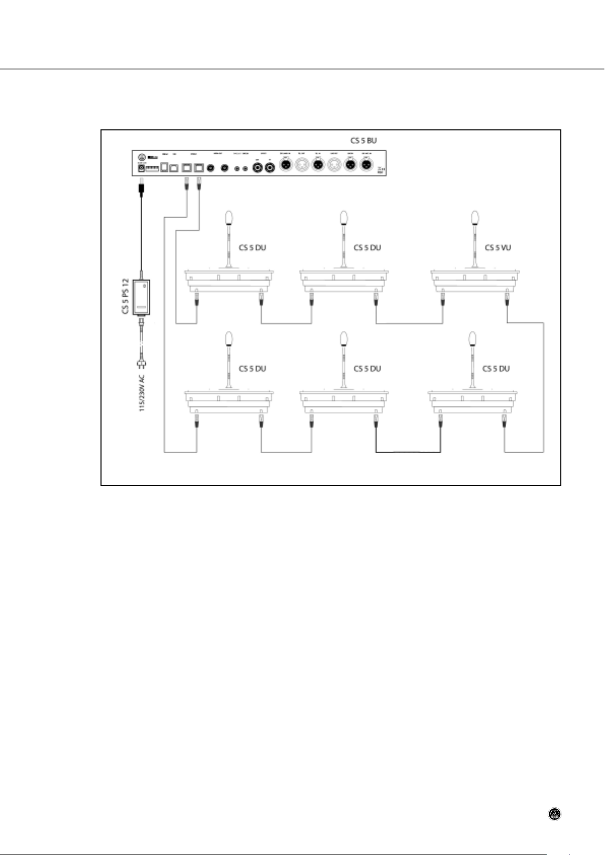
2.2.1 Simple Discussion System
Example 1: Simple discussion system.
Example 1 above shows the wiring diagram for a simple discussion system. A system of this kind may comprise any
combination of CS 5 DU and CS 5 VU microphone stations. Since the system shown includes only six microphone stations, a single CS 5 PS 12 power supply connected to the Base Unit is enough to power the entire system.
CS 5 User Manual
- 8 -
Page 9
Section 2: Notes on Wiring and System Examples
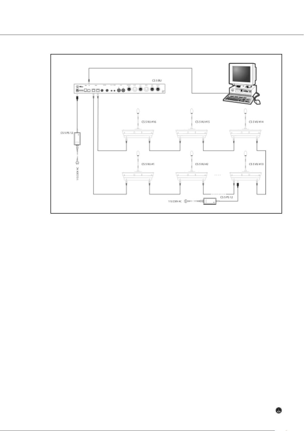
2.2.2 Computer-controlled Discussion System
Example 2: Larger discussion system with computer control.
Example 2 above shows a larger discussion system with more than six microphone stations and computer control. To
ensure stable powering even if one power supply fails, connect one CS 5 PS 12 power supply to the Base Unit, one
CS 5 PS 12 power supply to every sixth microphone station, beginning with the seventh in line counting from the Base
Unit, and connect the last microphone station to the second SYSTEM connector on the Base Unit.
The computer controlling the system is connected to the USB port on the Base Unit. In order to make optimum use of
all the functions offered by computer control, we recommend using CS 5 VU microphone stations, although computer
control will also work with CS 5 DU stations.
CS 5 User Manual
- 9 -
Page 10

Section 2: Notes on Wiring and System Examples
2.2.3 Infrared Interpretation System
Example 3: Basic layout and wiring diagram for an interpretation system for three conference languages with infrared
signal distribution.
The panel microphones (2 shown in the layout diagram above) are connected to a microphone mixer, which feeds the
LINE IN input on the Base Unit. The room sound system is fed by the Base Unit LINE OUT output. The four Interpreter
Stations in the two interpretation booths are connected in a closed loop to the two SYSTEM connectors on the Base
Unit.
CS 5 User Manual
- 10 -
Layout
Wiring Diagram
Page 11
Section 2: Notes on Wiring and System Examples
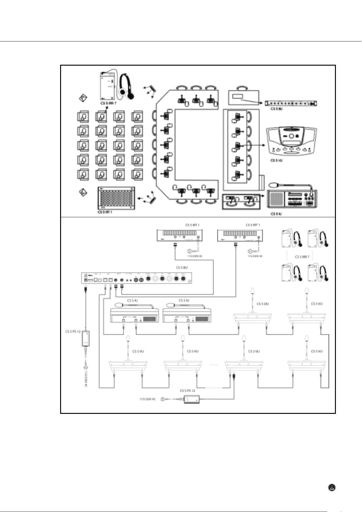
2.2.4 Large Conference System with Interpretation Booths
Example 4: Large conference system layout and wiring diagram.
Example 4 shows a large conference system with CS 5 VU microphone stations with voting and polling functions, an
interpretation booth for one target language, and an infrared distribution system for the audience. The chairperson, panelists, and delegates can listen to the loudspeakers on the Delegate Stations or use the headphones to listen to the interpreters. Since all microphones are connected to CS 5 microphone stations, no external microphone mixer is needed.
The audience can listen to the floor signal or interpretation on their CS 5 IRR 7 infrared receivers with channel selec-
CS 5 User Manual
- 11 -
Layout
Wiring Diagram
Page 12

Section 2: Notes on Wiring and System Examples
tors. The wiring diagram shows how all microphone stations including the Interpreter Stations are daisy-chained together
in a closed loop.
To ensure stable powering even if one power supply fails, connect one CS 5 PS 12 power supply to the Base Unit, one
CS 5 PS 12 power supply to every sixth microphone station, beginning with the seventh in line counting from the Base
Unit, and connect the last microphone station to the second SYSTEM connector on the Base Unit.
CS 5 User Manual
- 12 -
Page 13
Section 3: CS 5 BU Base Unit
3.1 General
The CS5 BU is the Base Unit required for any CS 5 system configuration. It synchronizes all system components and
generates the floor audio channel. you can connect to the Base Unit up to 5,000 microphone stations (Delegate Stations, Chairperson Stations, and Interpreter Stations); external analog audio sources; an external amplifier; an audio
recording device; and one or more infrared radiators.
The CS 5 BU provides the following basic control functions:
- NOM limitation: maximum number of microphones that may be open at any time, selectable from 1 to 64
- Two selectable automatic microphone activation modes
- Voting initiated from a Chairperson Station
- Driving the infrared radiator panels
More control functions are available through computer control using the CS5 ConferControl software.
3.2 Front Panel
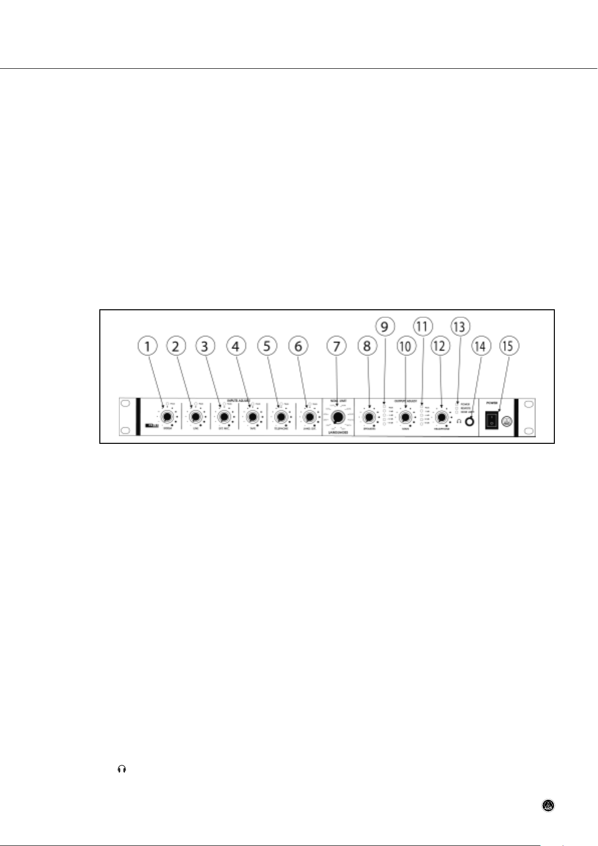
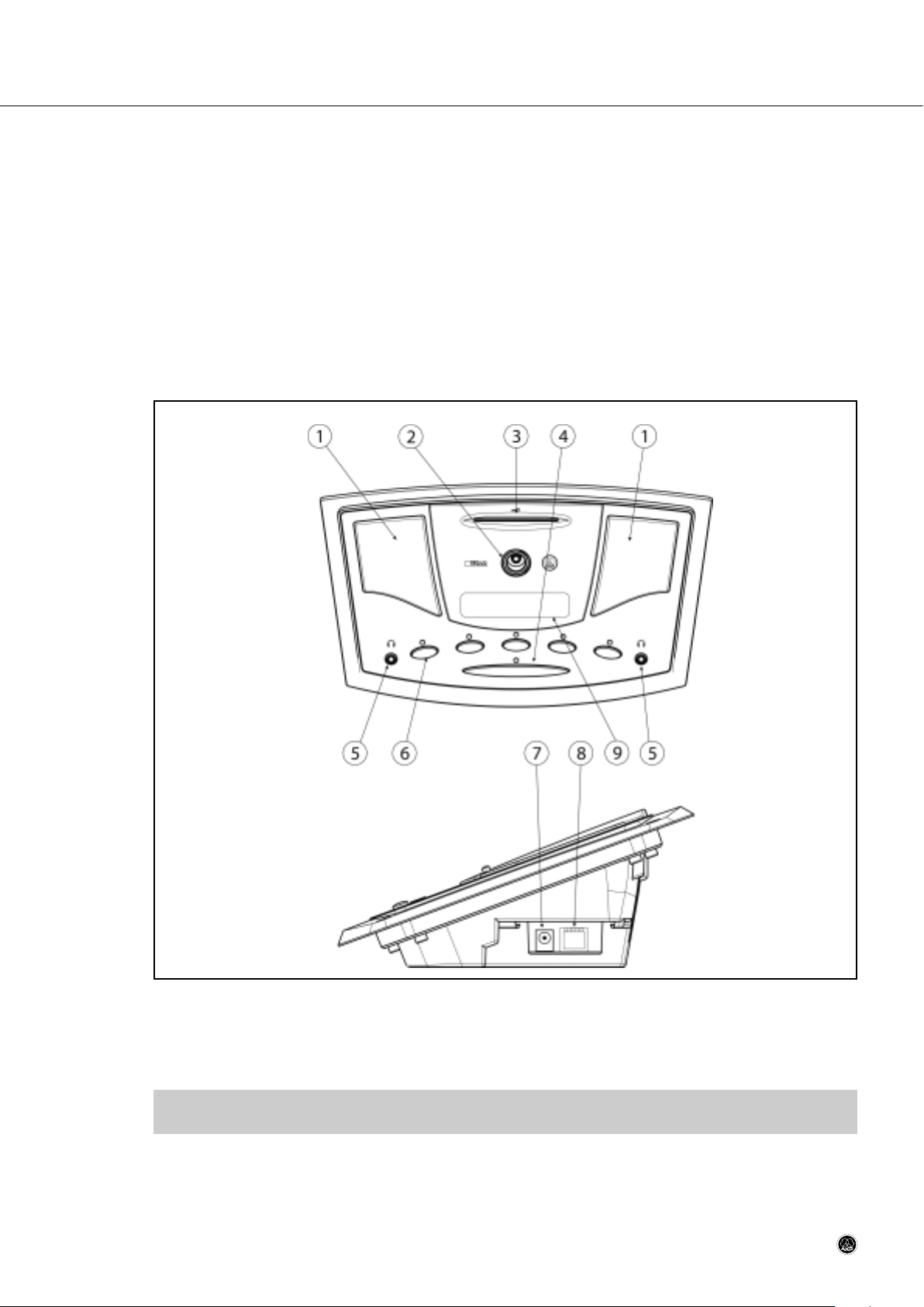
Fig. 1: CS 5 BU front panel.
1 SYSTEM: Sets the level of the sum of all open microphones on the microphone stations.
2 LINE: Sets the level of the rear panel LINE IN line level input.
3 EXT. MIC: Sets the level of the rear panel EXT. MIC IN microphone level input.
4 TAPE: Sets the level of the rear panel TAPE IN input for an external audio source.
5 TELEPHONE: Sets the level of the rear panel TEL. IN input for an external telephone hybrid.
6 LANG. EXT.: Sets the level of the rear panel EXT. LANG. IN input for an external hardwire or wireless microphone
used by an interpreter working outside the interpretation booths.
7 NOM LIMIT: Sets the maximum number of microphones (NOM) that may be open simultaneously at any time and
the number of audio channels available for interpretation. "1/63" means one open microphone and 63 interpretation channels, "64/0" means 64 open microphones and no interpretation channel.
8 SPEAKERS: Sets the level of the signal fed to the loudspeakers on the microphone stations.
9 LED level meter indicating the level set by the SPEAKERS control (8). Set the SPEAKERS control (8) so that the
red Peak LED will only flash occasionally at very loud signals.
10 MAIN: Sets the level of the rear panel LINE OUT line-level output.
11 LED level meter indicating the level set by the MAIN control (9). Set the MAIN control (9) so that the red Peak LED
will only flash occasionally at very loud signals.
12 HEADPHONE: Sets the level of the headphone output (14) to the right of the HEADPHONE control.
13 Status LEDs: The CS 5 BU provides three status LEDS:
POWER (green) is lit to indicate that power to the Base Unit is ON.
REMOTE (yellow) flashes to indicate that data is being transmitted.
NOM LIMIT (yellow) flashes to indicate a synchronization error.
Upon powering up, the REMOTE and NOM LIMIT LEDs will flash alternately for a few seconds to indicate the system is synchronizing and go out as soon as synchronization is completed.
14 : ¼" TRS headphone jack for stereo headphones only. (Using mono headphones may damage the unit.)
15 POWER: Switches power to the Base Unit ON ("I") or OFF ("0").
CS 5 User Manual
- 13 -
Page 14

Section 3: CS 5 BU Base Unit
3.3 Rear Panel
Fig. 2: CS 5 BU rear panel.
16 Dip switches: This set of dip switches allows you to route the various inputs to either the NORMAL bus or the
EFFECTS bus, activate or deactivate NOM limitation on the SYSTEM BUS and LINE OUT outputs, mute the EXT. LANG.
signal. Refer to section 3.4.
17 USB port: Enables the Base Unit to be controlled from a computer. Computer control works best with CS5 VU ad-
vanced delegate stations. The CS5 DU may not provide all the functions that may be required for more complex
systems.
18 SYSTEM: These two RJ 45 connectors provide the inputs, outputs, and power voltage for the microphone stations
connected to the Base Unit. Daisy-chain the microphone stations and connect the last station in the chain to the
second SYSTEM connector on the Base Unit. This makes sure that if one microphone station fails, all other stations will remain fully functional.
19 INFRA OUT: These two coaxial connectors carry the same signal for the CS5 IRT1 or CS5 IRT2 infrared radiators.
This signal includes the output signals from the interpretation booths (channels 1-6) and the NORMAL bus signal
(channel 0).
20 TAPE OUT: Unbalanced TRS mini jack carrying the NORMAL bus mono signal for recording.
21 TAPE IN: Unbalanced TRS mini jack for connecting the output of an external recording device. The input signal is
fed to the DIRECT/TELEPHONE bus and can be routed to the NORMAL or EFFECTS buses, too.
22 EFFECT OUT: Balanced TRS ¼" jack for sending the EFFECTS bus signal to an external effects device, e.g. a feed-
back eliminator.
23 EFFECT IN: Balanced TRS ¼" jack for receiving the output signal of an external effects device. This signal is fed
to the NORMAL bus.
24 EXT. LANG. IN: Balanced XLR line-level input for an external microphone mixer or AKG wireless microphone re-
ceiver providing an additional interpretation channel. The input signal can be muted or fed to language channel 1
which is part of the infrared signal.
25 TEL. OUT: Balanced XLR connector carrying the output signal of the DIRECT/TELEPHONE bus.
26 TEL. IN: Balanced XLR input for the output signal of a telephone hybrid. The signal is fed to the NORMAL bus.
27 LINE OUT: Balanced XLR connector carrying the NORMAL bus signal for the conference room sound system.
28 LINE IN: Balanced XLR input for a line-level audio source such as a CD player or A/V equipment.
29 EXT. MIC. IN: Balanced XLR microphone-level input with 48-V phantom power for an external hardwire or wire-
less microphone.
30 DC 48V / 3A IN: DC input for connecting the CS5 PS 12 power supply.
CS 5 User Manual
- 14 -
Page 15
Section 3: CS 5 BU Base Unit
3.4 Setting Up the Base Unit
Important:
• To avoid interference problems, make sure that all audio cables you are going to connect to the Base
Unit audio outputs are shorter than 10 feet (3 m).
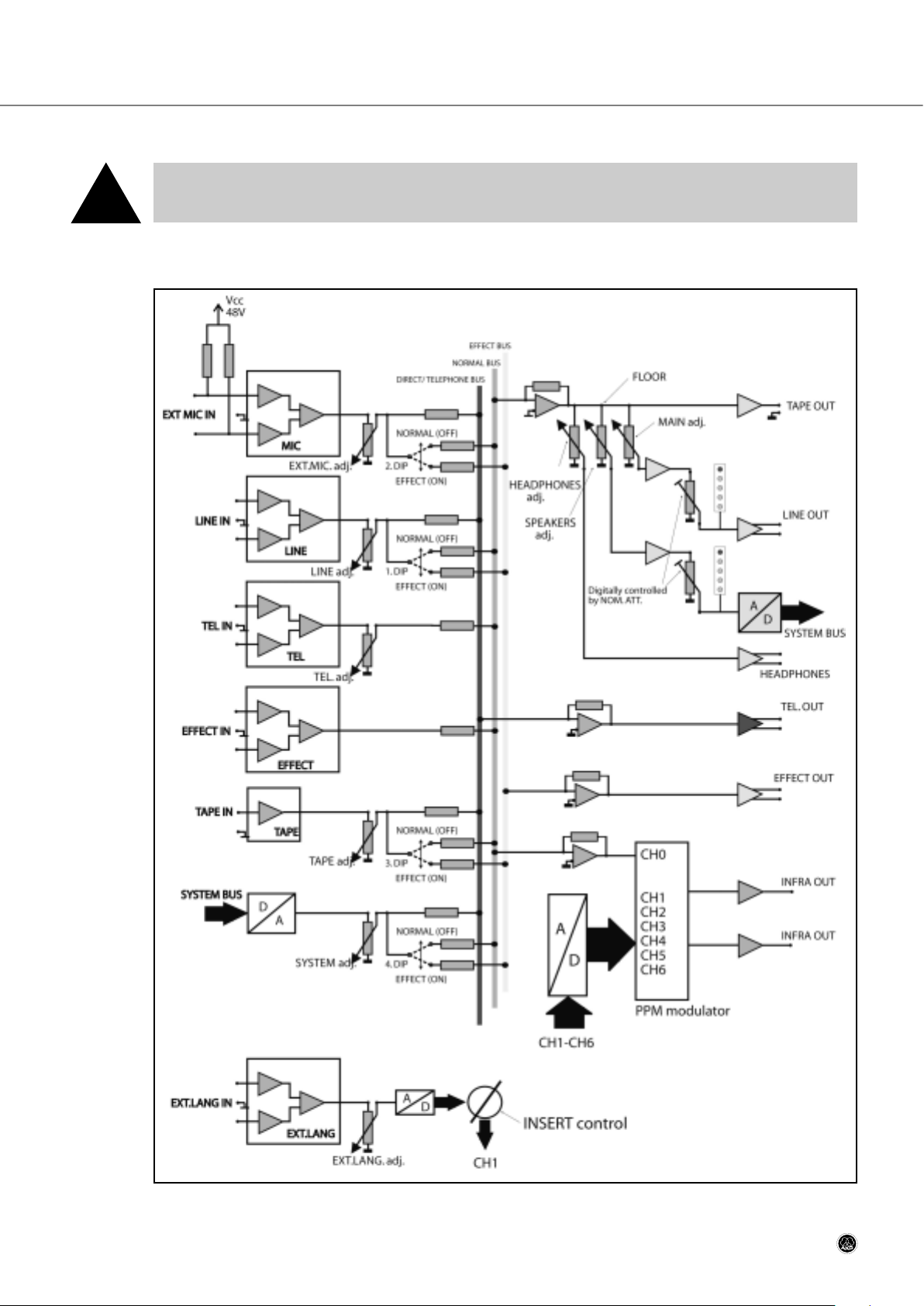
3.4.1 Block Diagram
Fig. 3: Block diagram of the CS5 BU analog section.
CS 5 User Manual
- 15 -
!
Page 16
Section 3: CS 5 BU Base Unit
3.4.2 Configuring the Dip Switches
1. Before powering up, set all front panel level controls to minimum (smallest dot) and set the rear panel dip switches
as required. Refer to fig. 3 on page 15 and Table 1 below.
Table 1: Base Unit dip switches.
• Dip switches S1 to S4 route the LINE, EXT. MIC., TAPE, and SYSTEM inputs to either the NORMAL or EFFECTS bus.
The NORMAL bus feeds the mixed input signals to the TAPE, LINE, SYSTEM, , and INFRA outputs.
The EFFECTS bus signal is available at the EFFECT output where you can connect a feedback eliminator or other
effects device. Connect the output of your effects device to the EFFECT IN jack on the rear panel. The processed
signal is fed to the NORMAL bus. As long as no effects device is connected, the signal is routed to the NORMAL
bus.
• Dip switches S5 and S6 let you activate and deactivate NOM attenuation. NOM (Number of Open Microphones) attenuation reduces the volume of the loudspeakers in a sound system depending on the number of microphones
that are active at any time. The more microphones are open, the more the loudspeaker volume is reduced. S5 allows you to activate NOM attenuation for the loudspeakers on the microphone stations connected to SYSTEM outputs. S6 lets you activate NOM attenuation on the LINE OUT signal that feed the room sound system.
• Dip switch S7 allows you to select the input signal for system channel 1. To route the assigned Interpreter Station
output to channel 1, set S7 to "0". To route the EXT. LANG. input to channel 1, set S7 to "1". You can use the latter configuration for a consecutive interpreter with a hardwire or wireless microphone.
• Dip switch S8 selects one of two microphone activation modes.
- With S8 in position "0", a microphone will be switched on immediately on pressing the talk button ("requesting the
floor") if a microphone channel is available. If no microphone channel is available, the microphone requesting the
floor will be put on the waiting list.
- With S8 in position "1", a microphone will be switched on immediately on pressing the talk button if a microphone
channel is available. If no microphone channel is available, the floor request on top of the waiting list will be deleted
and the last microphone requesting the floor will be added to the waiting list.
3.4.3 Selecting NOM Limitation/Interpretation Channels
• Set NOM LIMIT (7) to the desired ratio between the maximum number of microphones that may be open at any
time and the number of channels available for interpretation.
If no interpretation is needed, you may set NOM LIMIT to "64/0", allowing 64 microphones to be open simultaneously. To reduce the number of open microphones, set NOM LIMIT to a lower position.
If interpretation will be provided, set NOM LIMIT for the number of interpretation channels required (e.g., "48/16"
for any number of interpretation channels up to 16 and 48 open microphones).
CS 5 User Manual
- 16 -
Dip switch
Function
Switch position
0 1
S1
routes LINE IN to
NORMAL bus EFFECTS bus
S2
routes EXT. MIC. IN to
NORMAL bus EFFECTS bus
S3
routes TAPE IN to
NORMAL bus EFFECTS bus
S4
routes SYSTEM BUS IN to
NORMAL bus EFFECTS bus
S5
switches NOM attenuation on SYSTEM BUS OUT
OFF ON
S6
switches NOM attenuation on LINE OUT
OFF ON
S7
EXT. LANG. signal
muted routed to Channel 1
S8
Microphone activation mode
Floor request opens available mic channel
or puts microphone on waiting list.
FIFO: Floor request opens available mic
channel or cancels earliest floor request.
Page 17

Section 3: CS 5 BU Base Unit
3.4.4 Powering Up
1. Set up all microphone stations referring to section 4 (page 18) and make all power connections.
2. Switch power to the Base Unit ON, wait for five seconds, switch the first twenty microphone stations ON, wait for
five seconds, switch the next twenty microphone stations ON, and so on.
Important:
• To avoid overloading your power line and causing a risk of fire when powering up, make sure never to
connect more than twenty microphone stations to a common circuit with a common power switch and
never switch more than twenty microphone stations ON at a time.
Systems with one or more CS 5 VU Microphone Stations
Important:
• When powering up for the first time or after making any changes to the system configuration, it is absolutely necessary to run the “LEARNING” routine by following steps 3 through 5 below. Failing to do
so will cause severe system malfunctioning!
3. Insert the SERVICE CARD supplied with the Base Unit into the card slot on any CS 5 VU microphone station.
4. Press soft buttons 1 and 5 simultaneously on the same microphone station into which you inserted the SERVICE
CARD.
5. As soon as the display reads “LEARNING SUCCEEDED”, remove the SERVICE CARD. The Base Unit has now stored
the system configuration and will load this configuration immediately after switching power ON the next time.
If you are not sure if the “LEARNING” routine has been run, run it again. This will cause no problem.
Important:
• Mark the SERVICE CARD clearly and unmistakably and keep it in a safe place. You will need to use it
every time you power up a newly set up mobile system for the first time and every time you made any
change to an existing (mobile or permanently installed) system configuration.
Note:
• If you lose your SERVICE CARD, order a replacement from your AKG Distributor.
Alternatively, you can program your own SERVICE CARD by changing the number of an existing chip card to “0”.
Refer to the Software Manual for information on how to program chip card numers.
Systems with CS 5 DU Microphone Stations only
• System configurations with CS 5 DU stations only cannot be stored in memory. To power up such a system, simply follow steps 1 and 2 above.
3.4.5 Setting Levels
1. Set up all microphone stations referring to section 4, make all power connections and switch power to the Base
Unit and all ancillary equipment ON. (Steps 5 through 9 in the Getting Started Quickly manual.)
2. Have people talk into the microphones on the microphone stations. You can set the SYSTEM control to maximum
without risking to overload the amplifier input.
3. You can set the level controls (INPUTS ADJUST) for all other inputs you will use to maximum without risking to overload the amplifier input.
4. Set the level controls for all unused inputs to minimum.
5. Use the SPEAKERS control (8) to set the volume level for the loudspeakers on the microphone stations just high
enough to get optimum intelligibility. Do not set SPEAKERS higher than to the point where the red Peak LED of the
bargraph (9) will only flicker occasionally. Excessive levels may cause audible distortion.
6. Use the MAIN control (10) to set the volume level for the room sound system just high enough to get optimum intelligibility and avoid feedback. Do not set MAIN higher than to the point where the red Peak LED of the bargraph
(11) will only flicker occasionally. Excessive levels may cause audible distortion.
7. Connect a pair of headphones to the jack on the front panel for monitoring the main mix on the NORMAL bus.
CS 5 User Manual
- 17 -
!!!
Page 18

Section 3: CS 5 BU Base Unit
The jack accepts all standard stereo headphones with a ¼" TRS jack plug.
• Set the HEADPHONE control (12) just high enough so you can comfortably monitor the main mix.
Important:
• Excessive headphone listening levels my damage your hearing. So use the HEADPHONE control with
care.
3.4.6 Selecting NOM Limitation/Interpretation Channels
• Set NOM LIMIT (7) to the desired ratio between the maximum number of microphones that may be open at any
time and the number of channels available for interpretation.
If no interpretation is needed, you may set NOM LIMIT to "64/0", allowing 64 microphones to be open simultaneously. To reduce the number of open microphones, set NOM LIMIT to a lower position.
If interpretation will be provided, set NOM LIMIT for the number of interpretation channels required (e.g., "48/16"
for any number of interpretation channels up to 16 and 48 open microphones).
CS 5 User Manual
- 18 -
!
Page 19
Section 4: CS 5 DU Delegate Station
4.1 Introduction
The CS5 DU is the basic microphone station for the CS 5 conference system. It provides a microphone connection with
talk button, two built-in loudspeakers, and two headphone jacks.
The loudspeakers reproduce the main mix ("floor signal") while the headphone jacks allow the user to listen to the floor
signal or one of three interpreted languages.
4.2 Controls, Inputs, and Outputs
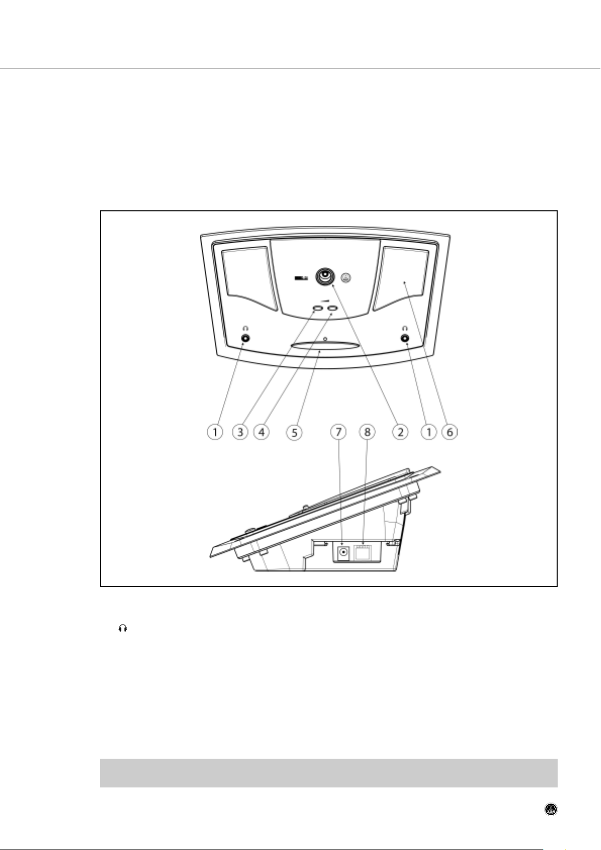
Fig. 4: Controls, inputs, and outputs on the CS5 DU.
1:Mini jack for stereo headphones.
2 Microphone input for connecting any of the gooseneck microphones listed in section 2.
3-4 Volume control buttons: The UP button (4) increases and the DOWN button (3) decreases the volume of the built-
in speakers or headphones connected to the microphone station.
• If no headphones are connected to the microphone station, the volume control buttons set the volume of the
built-in loudspeakers.
• If a single pair of headphones is connected to either headphone jack, the volume control buttons set the vol-
ume for that pair of headphones.
• If headphones are connected to both headphone jacks, the volume control buttons set the volume of both head-
phone channels.
Note: When the microphone is open, the volume of the loudspeakers will be attenuated by a specific amount de-
pending on the polar pattern of the microphone used. The headphones volume will not be affected.
CS 5 User Manual
- 19 -
Page 20
Section 4: CS 5 DU Delegate Station
5 Talk button: Pressing the talk button once activates the microphone. The status LED above the button will be lit.
Pressing the talk button again switches the microphone off. The status LED above the button will go out.
If no microphone channel is available, the microphone will not be activated before a channel becomes available.
The status LED will be flashing. Pressing the talk button again cancels the floor request and the status LED will go
out. The talk button also allows simple two-way (aye/no) voting (refer to section 5.4.2).
6 Loudspeakers.
7 DC input for connecting a CS5 PS 12 power supply.
8 System port: RJ45 connector for CS5 MK.. LAN cables. (Refer to section 2.2 for example wiring diagrams.)
4.3 Setting Up
4.3.1 Making Connections
1. Screw the microphone capsule on the gooseneck.
2. Screw the gooseneck into the microphone input (2).
3. Use the appropriate CS5 MK.. cables to connect the system ports on the microphone station to the system ports
on the preceding and subsequent microphone stations.
4.3.2 Selecting Operating Modes
Important:
• To avoid malfunctioning, do not change any dip switch settings on the Base Unit or any microphone station while power to the system is ON!
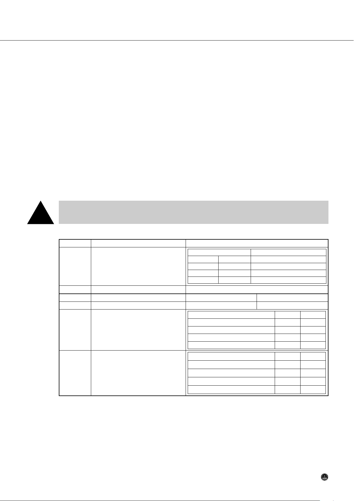
Table 2: CS 5 DU dip switches.
1. Referring to Table 2 above, set S1 and S2 for the microphone capsule you are going to connect to the microphone
station.
The settings of S1-S2 determine the frequency response and gain of the audio section as well as the amount of
gain reduction that is applied to the loudspeaker amplifier as soon as the microphone opens. Therefore, microphone
stations with unidirectional microphone capsules allow delegates to hear other talkers on the built-in loudspeakers even while the microphone is open.
CS 5 User Manual
- 20 -
Refer to
fig. 4
on page 18.
Fig. 4, p. 18.
!
Dip switches Function Switch positions
S1, S2 Match microphone station audio input
to microphone output signal.
S3 Unused
0 1
S4 Microphone muting on priority request: Microphone can be muted. Microphone will not be muted.
S5, S6 Switch left-hand phones output to channel
(language selection):
S7, S8 Switch right-hand phones output to channel
(language selection):
Channel S5 S6
Floor 0 0
CH 1 or EXT. LANG. 1 0
CH 2
0 1
CH 3 1 1
Channel S7 S8
Floor 0 0
CH 1 or EXT. LANG. 1 0
CH 2
0 1
CH 3 1 1
Dip switch Microphone model
S1 S2
0 0 CK 31 cardioid microphone
0 1 CK 33 hypercardioid microphone
1 1 CK 47, CK 80 shotgun microphones
Page 21

Section 4: CS 5 DU Delegate Station
Important:
• The amount of gain reduction applied to a cardioid capsule is rather low while hypercardioid and shotgun microphones will be attenuated more significantly. To avoid feedback problems, make sure to set
S1-S2 to the correct positions as per Table 2 on page 19.
2. Set the other dip switches to select the microphone priority/muting mode and select the input signals for the left
and right-hand headphone outputs.
CS 5 User Manual
- 21 -
!
Page 22
5.1 Introduction
The CS5 VU can be configured either as a delegate station with a voting function or as a chairperson station with voting and priority functions. Like the CS5 DU, it provides a microphone connection, talk button, two built-in loudspeakers, and two headphone jacks.
The loudspeakers reproduce the main mix ("floor signal") while the headphone jacks allow the user to listen to the floor
signal or one of 63 interpreted languages.
In addition, the CS 5 VU incorporates a chip card reader for user identification by conference control software. A liquidcrystal display and five soft buttons allow the user to call the meeting to order, initiate ballots, cast their vote, select languages for the headphone outputs, etc.
5.2 Control Panel, Inputs, and Outputs
Fig. 5: CS5 VU control panel, inputs and outputs.
1 Loudspeakers.
2 Microphone input for connecting any of the gooseneck microphones listed in section 2.
Note: When the microphone is open, the volume of the loudspeakers will be attenuated by a specific amount de-
pending on the polar pattern of the microphone used. The headphones volume will not be affected.
3 Chip card slot
4 Talk button: Basically, pressing the talk button once activates the microphone. The status LED above the button
will be lit. Pressing the talk button again switches the microphone off. The status LED above the button will go out.
Section 5: CS5 VU Voting/Chairperson Station
- 22 -CS 5 User Manual
Page 23

Section 5: CS5 VU Voting/Chairperson Station
CS 5 User Manual
- 23 -
Refer to
fig. 5
on page 21.
5:Mini jack for stereo headphones.
6 Soft buttons: These buttons control the functions assigned to them in the various menus shown on the display.
The buttons are assigned to numbers 1 through 5 in the lower display line from left to right.
7 DC input for connecting a CS5 PS 12 power supply.
8 System port: RJ45 connector for CS5 MK.. LAN cables. (Refer to section 2.2 for example wiring diagrams.)
9 Display: Two-line liquid-crystal display indicating the main menu for selecting functions and the submenus for set-
ting the parameters for each function.
Page 24
Section 5: CS5 VU Voting/Chairperson Station
5.3 Setting Up
5.3.1 Making Connections
1. Screw the microphone capsule on the gooseneck.
2. Screw the gooseneck into the microphone input (2).
3. Use the appropriate CS5 MK.. cables to connect the system ports on the microphone station to the system ports
on the preceding and subsequent microphone stations.
5.3.2 Selecting Operating Modes
Important:
• To avoid malfunctioning, do not change any dip switch settings on the Base Unit or any microphone station while power to the system is ON!
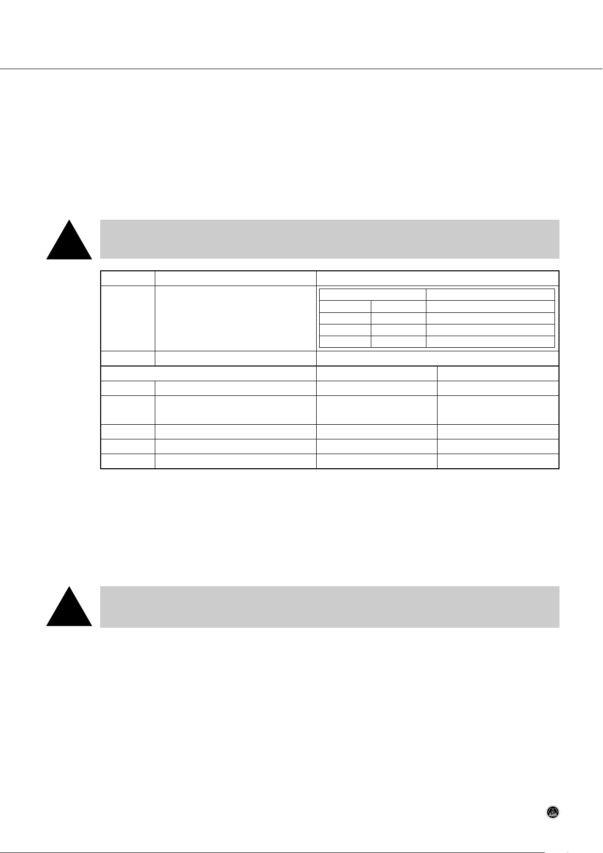
Table 3: CS 5 VU dip switches.
1. Referring to Table 3 above, set S1 and S2 for the microphone capsule you are going to connect to the microphone
station.
The settings of S1-S2 determine the gain of the audio section as well as the amount of gain reduction that is applied to the loudspeaker amplifier as soon as the microphone opens. Therefore, microphone stations with unidirectional microphone capsules allow delegates to hear other talkers on the built-in loudspeakers even while the
microphone is open.
Important:
• To avoid feedback problems, make sure to set S1 and S2 to the correct positions as per Table 3
above.
2. Set the other dip switches to select the microphone priority/muting mode and select the input signals for the left
and right-hand headphone outputs.
CS 5 User Manual
- 24 -
!
Fig. 5, p. 21.
!
Dip switches Function Switch positions
S1, S2 Match microphone station audio input
to microphone output signal.
S3 Unused
0 1
S4 Microphone muting on priority request: Microphone can be muted. Microphone will not be muted.
S5 Test mode:
Normal operating mode
as selected on S8
Test mode: Display indicates
data communication status.
S6 Configuration: Last user-selected configuration Factory default configuration
S7 Voting from delegate station: Enabled Disabled
S8 Voting Station operating mode: DELEGATE PRESIDENT
Dip switch Microphone model
S1 S2
0 0 CK 31 cardioid microphone
0 1 CK 33 hypercardioid microphone
1 1 CK 47, CK 80 shotgun microphones
Page 25
Section 5: CS5 VU Voting/Chairperson Station
5.3.3 DELEGATE Mode
If you have set dip switch S8 for DELEGATE mode, the Delegate main menu will appear on the display upon powering
up.
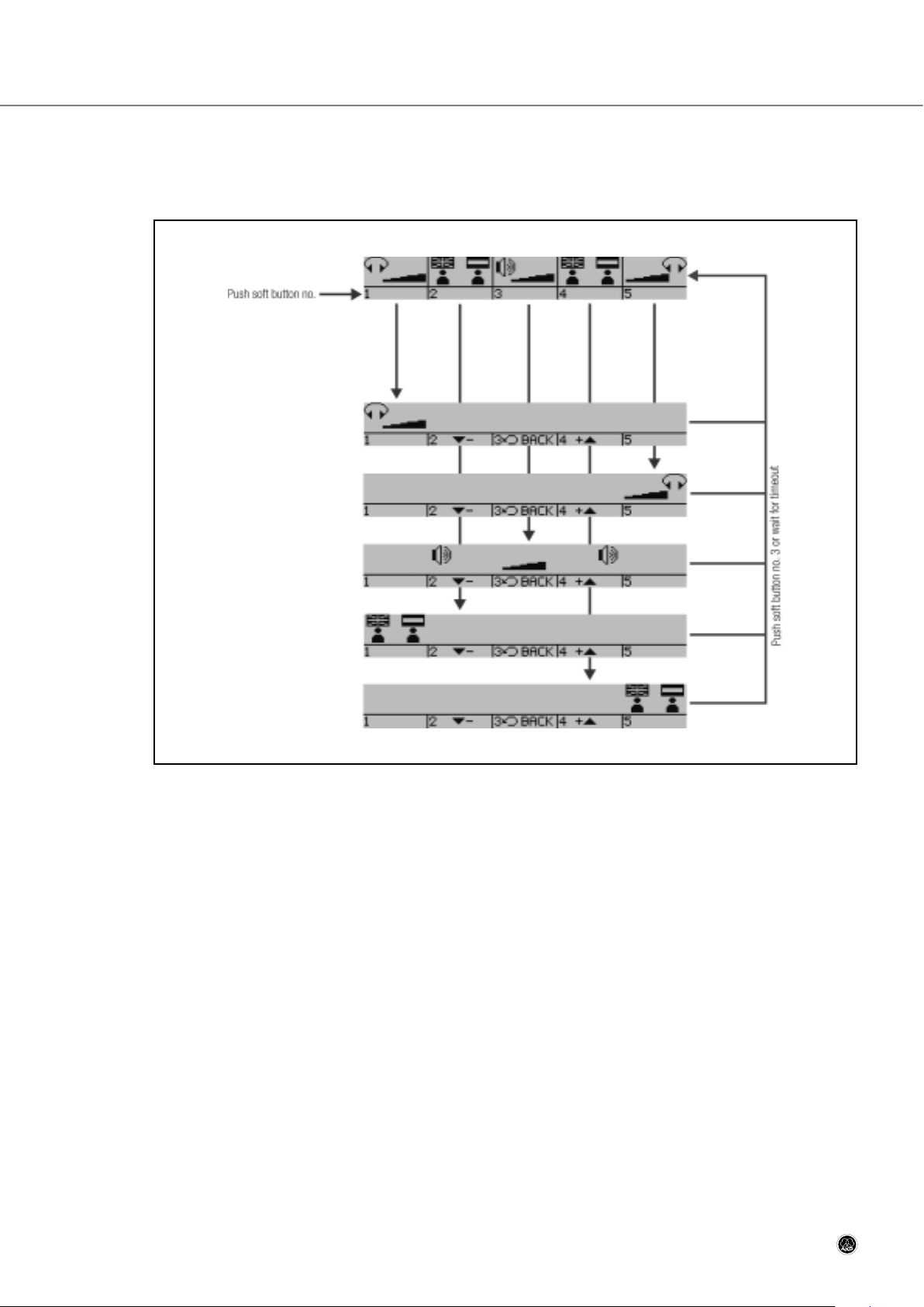
Fig. 6: Delegate menu and selectable submenus.
1. Press soft button 1 to select the volume control for the left-hand headphone output. Press soft buttons 2 and 4 to
decrease (-) or increase (+) the volume. A bargraph indicates the current setting.
Press soft button 3 (BACK) to return to the main menu.
2. Press soft button 2 to call up the language selection submenu for the left-hand headphone output. Press soft buttons 2 and 4 to select the desired language. Channel 0 carries the floor signal, channels 1-63 are assigned to the
interpreted languages listed in Table 4 in section 6.3.5 on page 32.
Press soft button 3 (BACK) to return to the main menu.
3. Press soft button 3 to select the loudspeaker volume control.
4. Press soft buttons 2 and 4 to decrease (2) or increase (4) the volume. A bargraph indicates the current setting.
Press soft button 3 (BACK) to return to the main menu.
5. Press soft button 4 to call up the language selection submenu for the right-hand headphone output. Press soft buttons 2 and 4 to select the desired language. Channel 0 carries the floor signal, channels 1-63 are assigned to the
interpreted languages listed in Table 4 in section 6.3.5 on page 32.
Press soft button 3 (BACK) to return to the main menu.
6. Press soft button 5 to select the volume control for the right-hand headphone output. Press soft buttons 2 and 4
to decrease (2) or increase (4) the volume. A bargraph indicates the current setting.
Press soft button 3 (BACK) to return to the main menu.
CS 5 User Manual
- 25 -
Page 26

Section 5: CS5 VU Voting/Chairperson Station
5.3.4 PRESIDENT Mode
If you have set dip switch S8 for PRESIDENT mode, the President main menu will appear on the display upon powering up.
Fig. 7: President menu and selectable submenus.
1. Press soft button 1 to select the volume control for the left and right-hand headphone outputs. Press soft buttons
1 and 2 to decrease (-) or increase (+) the volume for the left-hand headphones, buttons 4 and 5 to decrease (-)
or increase (+) the volume for the right-hand headphones. Two bargraphs indicate the current settings.
Press soft button 3 (BACK) to return to the main menu.
2. Press soft button 2 to call up the language selection submenu for the left and right-hand headphone outputs.
Press soft buttons 1 and 2 to select the desired language for the left-hand headphones, buttons 4 and 5 to select
the desired language for the right-hand headphones. Channel 0 carries the floor signal, channels 1-63 are assigned
to the interpreted languages listed in Table 4 in section 6.3.5 on page 32.
Press soft button 3 (BACK) to return to the main menu.
3. Press soft button 4 to select the loudspeaker volume control.
Press soft buttons 2 and 4 to decrease (-) or increase (+) the volume. A bargraph indicates the current setting.
Press soft button 3 (BACK) to return to the main menu.
4. Press soft button 3 to set the microphone station to priority mode. In priority mode, pressing the talk button once
always activates the microphone and mutes the microphones on all microphone stations where priority muting has
been enabled.
To quit priority mode and return to the main menu, press soft button 4 (CLEAR).
5. Press soft button 5 to initiate a ballot or opinion poll. Refer to section 5.4 below.
6. To return to the main menu, press soft button 3 (BACK).
CS 5 User Manual
- 26 -
Page 27
Section 5: CS5 VU Voting/Chairperson Station
5.4 Voting/Polling
Important:
• If anything goes wrong while a ballot or poll is in progress, the display will go dark (in case of a power
failure) or show "VOTING FAILED". Voting/polling data may be lost or corrupted.
• To ensure correct results, always repeat the entire ballot or poll once the problem has been corrected.
5.4.1 Controlling a Ballot or Opinion Poll (PRESIDENT Mode)
• Instruct the president of the meeting how to control a complete voting or polling procedure:
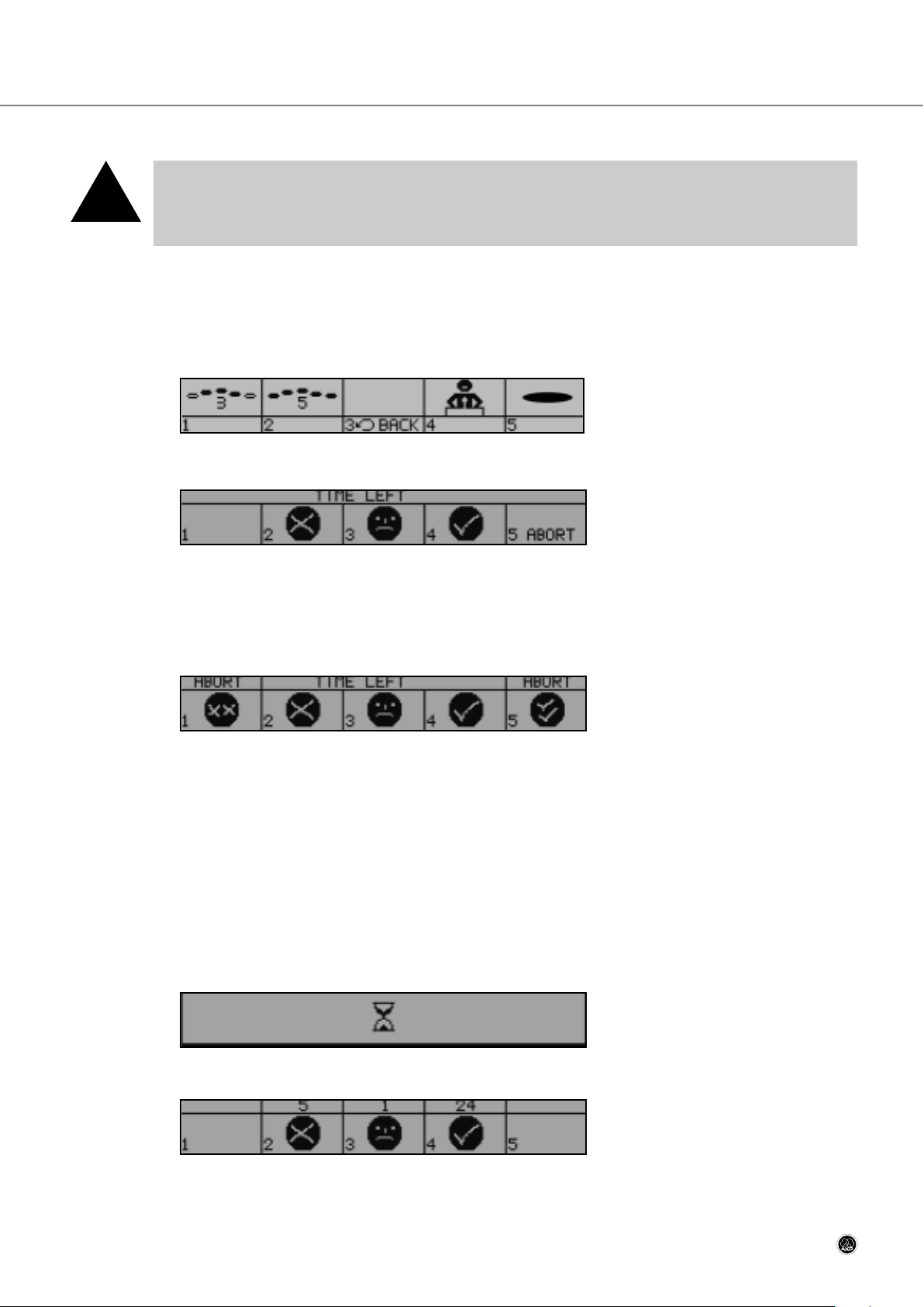
1. From the President main menu, press soft button 5 (VOTE) to call up the voting control menu:
2a. To start a three-way (no/abstention/aye) ballot, press soft button 1. The display will change like this:
The delegates may now cast their votes.
As long as "TIME LEFT" is shown on the display, you can press soft button 5 (ABORT) to stop the procedure and
return to the voting control menu.
2b. To start an opinion poll (five options), press soft button 2. The display will change like this:
2c. To start a two-way (aye/no) vote, press soft button 5. This allows two-way voting from both CS 5 VU and CS 5 DU
microphone stations.
The delegates may now cast their votes. Refer to section 5.4.2 on page 27.
As long as "TIME LEFT" is shown on the display, you can press soft button 5 (ABORT) to stop the procedure and
return to the voting control menu.
3. The delegates may now cast their votes.
As long as "TIME LEFT" is shown on the display, you can press soft buttons 1 and 5 (ABORT) simultaneously to
stop the procedure and return to the voting control menu.
4. As soon as all delegates have pressed their voting buttons, the votes are counted automatically and this screen
appears on the display (results shown below are examples):
5. When the counting is done, the display will change like this…
CS 5 User Manual
- 27 -
!
Page 28

Section 5: CS5 VU Voting/Chairperson Station
… or like this…
… to show the votes have been counted. The top line on each CS 5 VU microphone station indicates the results.
6. Press any button to return to the President main menu.
5.4.2 Voting in DELEGATE Mode
• Instruct the delegates how to cast their votes:
1. When the president starts a ballot or opinion poll, the display on each delegate station registered for voting changes
like this…
… for three-way voting, or like this…
… for an opinion poll.
2a. Press the appropriate soft button to cast your vote.
2b. Simple aye/no voting dan be done from both CS 5 VU and CS 5 DU microphone stations:
- To vote “aye”, press the talk button when the chairperson asks you to do so.
- To vote “no”, ignore the chairperson’s request and do not press any button until the voting time has elapsed.
3. As soon as all delegates have pressed their voting buttons, the votes are counted automatically and this screen
appears on the display:
4. When the counting is done, the display will change like this…
… or like this…
… to show the votes have been counted.
5. Press any soft button to return to the Delegate main menu.
CS 5 User Manual
- 28 -
Page 29

Section 5: CS5 VU Voting/Chairperson Station
5.5 Chip Card Identification
Chip card identification is only available in a computer controlled system and the identification system only accepts AKG
chip cards. The chip card reader and control software check the identity of the person using the microphone station as
well as their priority and voting rights, allowing votes to be weighted or classified. This system also allows holders of
AKG chip cards to exercise their rights not only from their assigned microphone stations, but from any CS 5 VU microphone station in the conference system.
Note: To assign chip cards to persons, enter each person's data into the database in the CS 5 ConferControl soft-
ware. For details, refer to the ConferControl Operating Manual.
• Instruct users how to identify themselves to the system:
1. Insert the chip card into the chip card reader slot with the contacts pointing toward the slot as shown on the display:
The main menu appears on the display.
If you inserted the card the wrong way, or if you inserted an incompatible card, a warning message ("WRONG
CARD") will appear on the display:
Important:
• Inserting any card other than an AKG chip card causes malfunctioning and may even damage the card
or the equipment.
2. Remove the chip card by the time the session is over.
Note: If two persons share a single CS5 VU, both persons can vote by taking turns using their chip cards and pro-
ceeding as describe in sections 5.4 and 5.5 above.
CS 5 User Manual
- 29 -
!
Page 30

Section 6: CS 5 IU Interpreter Station
6.1 Introduction
The CS 5 IU adds interpretation capabilities to the CS 5 conference system. It provides inputs and outputs for a gooseneck microphone and headphones or a headset, a built-in loudspeaker, source and target language selectors, a microphone switch, cough button, "slow" signal button, and a signal button for requesting a technician's assistance.
6.2 Control Panel, Inputs, and Outputs
Fig. 8: CS 5 IU control panel, inputs, and outputs.
INPUT SELECT: These four keys select the source language signal that is routed to the headphone output.
1 FLOOR: Selects the floor (main mix) signal.
2A:Selects the next item from a list.
3B:Selects the previous item from a list.
4 RELAY: Selects the relay-language channel specified by the organizer or chief interpreter.
5 Backlit LC display.
6 BASS: Cuts/boosts the low-frequency range of the headphone or loudspeaker signal.
7 TREBLE: Cuts/boosts the high-frequency range of the headphone or loudspeaker signal.
8 VOLUME: Sets the volume level of the headphone or loudspeaker signal.
9 Microphone status LED: Indicates the current operating status of the microphone:
• Lit: microphone is open (MICROPHONE switch (14) set to "ON").
• Dark: microphone is off or muted (MICROPHONE switch (14) set to "OFF" or "MUTE").
CS 5 User Manual
- 30 -
Page 31

Section 6: CS 5 IU Interpreter Station
Refer to
fig. 8
on page 29.
10 Loudspeaker: The loudspeaker is automatically muted when a pair of headphones is connected to the headphone
output (18).
When no headphones are connected to the Interpreter Station, the loudspeaker reproduces the selected incoming
signal. The rotary controls (6), (7), and (8) adjust the loudspeaker signal.
OUTPUT SELECT: These keys select one of two pre-selected target language channels and allow the interpreter to re-
quest the talker to speak more slowly or to call a technician for assistance (provided a technician is available).
11 A: Routes the microphone signal to the target-language channel specified for this booth.
12 CALL: This key has two functions:
• Pressing <CALL> momentarily sends a "speak slowly" signal to the talker. The red LED above the <CALL>
key and the green LED on the microphone arm of the talker's Delegate Station will flash for about 5 seconds.
The display (5) shows the message "SENDING SLOWLY PLEASE". Pressing <CALL> momentarily again before
the five seconds have elapsed will stop the signal.
• Holding down <CALL> for at least 3 seconds activates an appropriate message on the computer monitor
alerting the technician that an interpreter needs assistance. To cancel the signal, hold down <CALL> again for
about 3 seconds.
13 B: Routes the microphone signal to the source-language channel specified for this booth.
14 MICROPHONE: This toggle switch provides three positions:
• OFF: The microphone is off and the LED on the microphone arm is dark.
• ON: The microphone is open and the LED on the microphone arm is lit.
• MUTE (cough button function): The microphone is muted and the LED on the microphone arm is dark for as
long as you hold the switch in the MUTE position. The switch will return to the ON (center) position as soon as
you release the switch.
15 Microphone input.
16 External microphone input: This mini jack allows you to connect the microphone of a headset if the client spec-
ifies headsets for the interpreters instead of microphone arms and separate headphones.
17 System port: RJ45 connector for CS5 MK.. LAN cables. (Refer to section 2.2 for example wiring diagrams.)
18 : Mini jack for stereo headphones.
6.3 Setting Up
Important:
• According to international practice as specified by the AIIC, each interpretation booth must provide
two Interpreter Stations because interpreters never work alone. Having an interpreter work alone in a
booth would be unethical.
Note: In the following sections, the terms "source language", "target language", and "relay language" will be used
frequently.
The source language is the language an interpreter translates into another language. That other language is
called the target language.
A relay language is a target language that is used as a source language by another interpreter if that inter-
preter is not qualified to interpret the original source language.
6.3.1 Making Connections
1. Screw the microphone capsule on the gooseneck.
2. Screw the gooseneck into the microphone input.
3. Use the appropriate CS5 MK.. cables to connect the system ports on the microphone station to the system ports
on the preceding and subsequent microphone stations.
CS 5 User Manual
- 31 -
!
Page 32
Section 6: CS 5 IU Interpreter Station
6.3.2 Selecting Station Addresses
1. Set the MICROPHONE switch to "OFF" to switch the microphone off.
2. Press <FLOOR> + <CALL> + <RELAY> simultaneously to enter service mode. The display changes like this:
3. Select <NEXT> (press <RELAY>) to bring up this screen:
4. Press <INPUT/A> or <INPUT/B> to call up the lowest possible address for the Interpreter Station (e.g., “002”):
5. Press <INPUT/A> to select the next higher address or <INPUT/B> to select the next lower address.
Important:
• Be sure to assign a unique address to each Interpreter Station. Use consecutive numbers starting with
"1". Assigning the same address to more than one Interpreter Station would cause system malfunctioning.
Assign one odd and one even number to the Interpreter Stations in each booth, starting with "1", for instance,
1-2 (booth no. 1), 3-4 (booth no. 2), 5-6 (booth no. 3), etc. Make sure that the odd number is lower than the even
number in each booth.
6. Select target language channels: refer to section 6.3.3 below.
7. Repeat steps 1-4 above for each Interpreter Station.
8. To leave service mode and return to normal mode, press <FLOOR> + <CALL> + <RELAY> again.
6.3.3 Selecting Target Language Channels
• On your list of language pairs, assign one audio channel to each target language (e.g., channel 1 -> English, channel 2 -> French, etc.).
• Assign each of these channel numbers to one interpretation booth (e.g. booth no. 1 -> English, booth no. 2 ->
French, etc.).
If a relay language has been specified, assign a channel number to the relay language. Invariably, the relay language will be identical to one of the target languages.
• Route output A on each Interpreter Station in the same booth to the same language channel (e.g., select channel
1 (English) for output A on each Interpreter Station in booth 1, channel 2 (French) for output A on each Interpreter
Station in booth 2, etc.)
• Route output B on each Interpreter Station in each booth to the language channel number assigned to the relay
language (e.g., channel 3 for Italian).
To select output channels,
1. In service mode, press <RELAY) and <FLOOR> to call up this screen:
SERVICE MENU
OUTPUT ‘A’ CHANNEL
<<PREV < 002 > NEXT>>
SERVICE MENU
SINGLE MODE
<<PREV < 002 > NEXT>>
SERVICE MENU
SINGLE MODE
<<PREV < OFF > NEXT>>
SERVICE MENU
EXIT WITHOUT SAVING
<<PREV |
———————
| NEXT>>
CS 5 User Manual
- 32 -
!
Page 33

Section 6: CS 5 IU Interpreter Station
Note: If you have quit service mode, switch the microphone off and press <FLOOR> + <CALL> + <RELAY> si-
multaneously to enter service mode, then use <RELAY> and <FLOOR> to call up the above screen.
2. Press <INPUT/A> to increase the channel number and <INPUT/B> to decrease the channel number.
3. Press <RELAY> to select the name of the language ("OUTPUT ‘A’ MNEMONIC") you assigned to the channel number you just selected. Refer to section 6.3.5 for a list of languages and their abbreviations available on the
CS 5 IU.
4. Press <RELAY> to call up the language selection menu for output B ("OUTPUT ‘B’ CHANNEL").
5. Press <INPUT/A> and <INPUT/B> to select the channel number you assigned to the relay language.
6. Press <RELAY> to select the name of the language ("OUTPUT ‘B’ MNEMONIC") you assigned to the relay channel. Refer to section 6.3.5 for a list of languages and their abbreviations available on the CS 5 IU.
7. Repeat steps 1-7 above for each pair of Interpreter Stations.
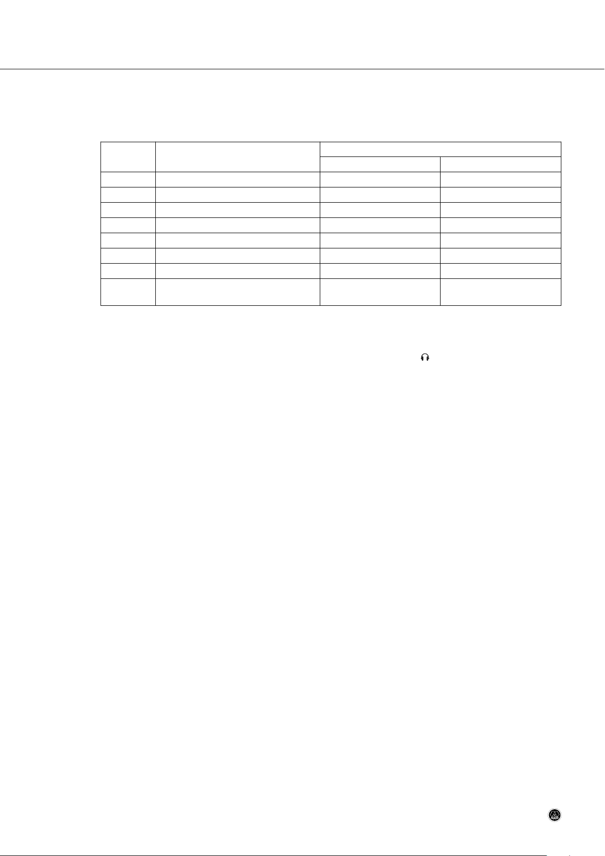
6.3.4 List of Available Language Names
Table 4: Available language names and abbreviations.
6.3.5 Selecting the Microphone Type
1. In service mode, press <RELAY> to call up this screen:
2. Use <INPUT/A> and <INPUT/B> to selct the micorphone type you connected to the Interpreter Station mic arm.
3. Press <RELAY> to call up the “SAVE CONFIGURATION” screen.
4. To save your settings, switch the microphone OFF and press <INPUT/A> and <INPUT/B> simultaneously.
5. To return to normal mode (main menu), press <FLOOR> + <CALL> + <RELAY> simultaneously.
Note: You cannot leave the service menu before having saved your settings in the “SAVE CONFIGURATION” screen.
SERVICE MENU
MICROPHONE TYPE
<<PREV <CK 31> NEXT>>
CS 5 User Manual
- 33 -
Abbreviation Language Abbreviation Language Abbreviation Language
ALB ALBANIAN GEO GEORGIAN POL POLISH
ARA ARABIC GER GERMAN POR PORTUGUESE
ARC ARAMAIC GRE GREEK RUM ROMANIAN
ARM ARMENIAN HEB HEBREW RUS RUSSIAN
AZE AZERBAIJANI HUN HUNGARIAN SER SERBIAN
BUL BULGARIAN ISL ICELANDIC SLO SLOVAK
CHI CHINESE GAI IRISH SLV SLOVENIAN
CRO CROATIAN ITA ITALIAN SPA SPANISH
CES CZECH JPN JAPANESE SUX SUMERIAN
DAN DANISH KUR KURDISH SWE SWEDISH
DUT DUTCH LAV LATVIAN TIB TIBETAN
ENG ENGLISH LIT LITHUANIAN TUR TURKISH
EST ESTONIAN MAC MACEDONIAN UKR UKRAINIAN
FIN FINNISH MLT MALTESE
FRA FRENCH NOR NORWEGIAN
Page 34

Section 6: CS 5 IU Interpreter Station
6.4 Using the Interpreter Station
Important:
• Before powering the system up, set the MICROPHONE switch on each Interpreter Station to "OFF" to
avoid "broadcasting" any unofficial conversations.
Upon system power-up,
• the display shows the message "SYSTEM STARTING…" until synchronization is completed. Once synchronization
is finished, the display shows the main menu.
• the microphone input is automatically routed to output A and the red LED above OUTPUT SELECT key <A> is lit.
The microphone will be open only if the MICROPHONE switch is in its center position ("ON"). When the microphone is open, the red LED on the microphone arm will be lit.
• if the MICROPHONE switches on both Interpreter Stations are in their "ON" positions, the microphone on the Interpreter Station with the lower (odd) address will be opened. The microphone on the Interpreter Station with the
higher (even) address will be muted. On the active Interpreter Station, the red LED above the active OUTPUT SELECT key and the red LED on the microphone arm will be lit, while the corresponding LEDs on the other Interpreter
Station will remain dark.
Instruct the interpreters how to use the Interpreter Stations:
1. Select your source language:
• If the person using the floor microphone speaks your source language, press <FLOOR>. You will hear the floor
talker on your headphones and the display shows the message "FLOOR".
• If you need your colleagues' relay, press <RELAY>. On your headphones, you will hear the voice of the inter-
preter working into the relay language. The display shows the message "RELAY".
The microphone signal will be automatically routed to output A.
• To select one of the other available source languages, press <INPUT/A> or <INPUT/B>. You will hear the se-
lected language on your headphones and the display indicates the selected language".
2.
Use the VOLUME, BASS, and TREBLE controls to adjust the headphone volume and sound for optimum intelligibility.
These controls also set the volume and sound of the loudspeaker on the Interpreter Station.
3. Select your target language:
• To interpret from the floor language (e.g., English) into your booth's target language (e.g., Portuguese), check
that output A is selected (the red LED above the OUTPUT SELECT <A> key is lit). If it is not, press <A>.
• If a speaker of your booth's target language (e.g., Portuguese) takes the floor and you are required to interpret
into the relay language (e.g., English), press <B> to select output B. The red LED above the OUTPUT SELECT
<B> key is lit and the headphones are automatically switched to the floor channel.
(Tech note: The floor channel is automatically fed to the language channel selected for output A to save dele-
gates the trouble of having to switch their headphones to the floor channel.)
Note: Pressing an OUTPUT SELECT key on one control panel will route the other control panel (which becomes a
"slave" to the first panel) in the booth to the same output channel. The appropriate LED on the "slave" control
panel will be lit accordingly.
4. Controlling the microphones:
• The interpreter who agreed to begin opens their microphone by setting the MICROPHONE switch to "ON" and
the other interpreter switches their microphone OFF (unless it is off already). The red LED on the open microphone and the red LED above the active OUTPUT SELECT key are lit.
Important:
• Make sure never to switch both microphones in your booth ON simultaneously. If you do, only one microphone will be activated and the other muted automatically, so the wrong microphone may come on.
• When it is time to relieve your colleague, you can do so in one of two ways:
- Method 1: the interpreter on duty switches their microphone OFF (the red LED on the microphone goes out)
and the other interpreter switches their microphone ON (the red LED on the microphone comes on).
CS 5 User Manual
- 34 -
!
!
Page 35

Section 6: CS 5 IU Interpreter Station
- Method 2: the interpreter taking over presses the appropriate OUTPUT SELECT key. The red LED on the microphone comes on, the relieved colleague's microphone is automatically muted, and the red LED on that microphone goes dark.
Note that when using this method, one microphone will always be open. To make sure your listeners will not hear
any of your internal conversations, always set the MICROPHONE switches on both control panels to OFF when
none of you is interpreting.
5. Controlling talkers:
• If the person delivering a speech talks too fast, press <CALL> momentarily. This causes the green LED on the
microphone arm on the talker's Delegate Unit to flash for five seconds. The display on your control panel shows
the message "SENDING SLOWLY PLEASE". To stop the signal before the five seconds are over, press <CALL>
again.
6. Calling a technician (if the system is computer controlled and a technician is available):
• If there is a technical problem or you have run out of water, etc. hold down <CALL> for at least three seconds.
This causes an appropriate message to appear on the computer monitor and the message "CALLING TECHNICIAN" to appear on your control panel display. To delete the messages, press and hold <CALL> again for at least
three seconds.
CS 5 User Manual
- 35 -
Page 36
Section 7: Infrared Transmission System
7.1 CS 5 IRT 1 and CS 5 IRT 2 Infrared Radiators
7.1.1 General
The CS 5 IRT 1 and CS 5 IRT 2 infrared radiators are capable of transmitting seven interpretation channels to the
CS 5 IRR 7 infrared receivers. The two radiator models are technically identical, except that the CS 5 IRT 2 is larger
than and provides about twice the radiation range of the CS 5 IRT 1.
Each infrared radiator comes complete with a mounting bracket for installation on a wall or ceiling.
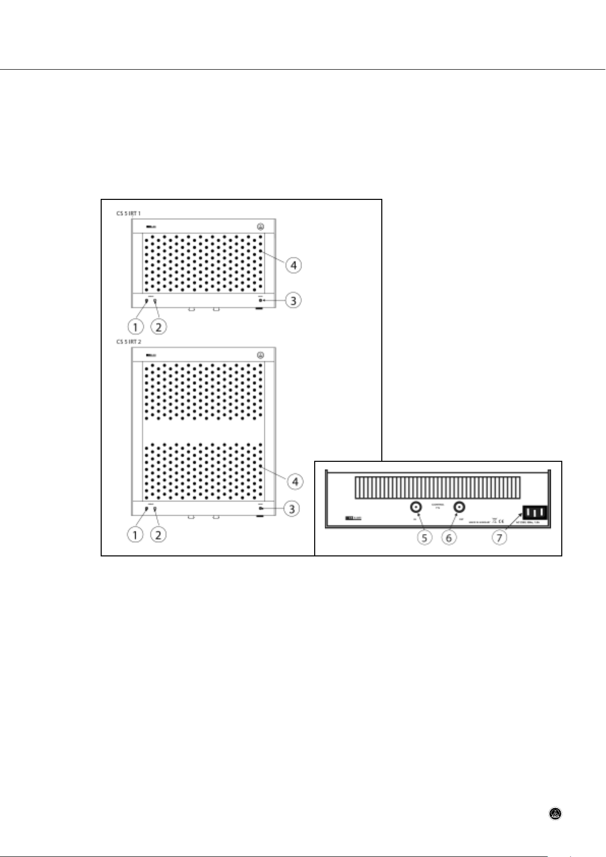
Fig. 9: CS 5 IRT 1 and CS 5 IRT 2 front views.
Fig. 9a: CS 5 IRT 1/CS 5 IRT 2 bottom panel.
1 Green OPERATE LED: The green OPERATE LED is lit to indicate that signal is being radiated.
2 Yellow OPERATE LED: The yellow OPERATE LED is lit to indicate that the infrared driver circuitry is in standby mode.
3 MAINS: This red LED is lit to indicate that power to the radiator is ON.
4 IREDs
5 IN: BNC input connector for the PPM modulated time-multiplexed signal driving the IREDs (infrared emitting diodes)
(7).
6 OUT: This BNC output connector is connected in parallel to the IN connector allowing you to daisy-chain several
infrared radiators.
7 Power input: Standard IEC power connector for 230 V/50 Hz.
7.1.2 Placement
• Basically, it is best to place the infrared radiators as close as possible to the area where the receivers will be used
and as high above the floor as practical. Diagram 1 in the Quickstart Manual shows an example of two infrared radiators covering the delegates' tables only.
Refer to
fig. 9a.
CS 5 User Manual
- 36 -
Page 37

Section 7: Infrared Transmission System
• To cover an entire room, place one infrared radiator in each corner of the conference room, at least 10 feet (3 m)
above the floor, aligning the front panel to face the opposite corner.
Walls and/or ceilings that are painted a dark color, paneled, or acoustically treated will absorb more infrared radiation than white surfaces, so you will need more infrared radiators in darker rooms.
• Sunlight, fluorescent lighting, and photo flashes may weaken infrared radiation. Therefore, try to place the infrared
radiators where they will not be exposed to natural or artificial light or use some extra IRTs.
Note: Working out the exact number of infrared radiators needed for optimum room coverage and placing them cor-
rectly can be a challenge in some rooms. As a rule of thumb, it is better to use many small (CS 5 IRT 1) radiators than only a few large ones (CS 5 IRT 2). If you need assistance, your dealer or nearest AKG Distributor will
be glad to help.
7.1.3 Mounting
• For mobile use, you can fix the support frame of the infrared radiator on a heavy standard loudspeaker stand.
• For permanent installations, you can directly screw the support frame on a wall or ceiling at any desired angle. To
mount a radiator in a corner, you may need additional angle brackets (available from hardware stores).
• To set the tilt angle of the radiator, slacken the set screws on the support frame, rotate the radiator to the desired
angle, and tighten the set screws.
7.1.4 Connections
Important: To avoid damage to any system components, do not lay, connect, or disconnect any cables while power to
the system is on. Always disconnect the entire system from power before making any changes to the wiring.
1. Use RG58 50-ohm coaxial cable and BNC connectors to connect one INFRA OUT jack on the Base Unit rear panel
to the IN BNC jack on the infrared radiator on the left side of the room.
2. Use a cable of the same length (or as nearly as possible) to connect the other INFRA OUT jack on the Base Unit
rear panel to the IN BNC jack on the infrared radiator on the right side of the room.
3. If you need to use more than one radiator on either bus, use RG58 50-ohm coaxial cable and BNC connectors to
connect the OUT jack on the first radiator to the IN jack on the subsequent radiator, and so on.
Note: To ensure consistent performance of the two radiators, keep the difference in length between the two cables
to a practical minimum (less than 164 feet/50 m).
4. Connect each infrared radiator to power.
The CS 5 IRT 1 and CS 5 IRT 2 infrared radiators have no power switches. Therefore, connect the power input on
each radiator to a switched 230 V/50 Hz power outlet protected by an appropriate fuse.
Important:
• If no switched power outlets are available at the site of a permanent installation, ask a qualified electrician to install the required number of outlets in the conference room and a suitable ON/OFF switch
in the control room in accordance with local electrical and occupational safety regulations.
CS 5 User Manual
- 37 -
!
Page 38

Section 7: Infrared Transmission System
7.2 CS 5 IRR 7 Infrared Receiver
7.2.1 General
The CS 5 IRR 7 is a light, portable infrared receiver for use with the CS 5 IRT 1 and CS 5 IRT 2 infrared radiators. It
provides seven selectable audio channels, a mini-jack headphone output, volume control, and ON key. The receiver is
powered by a standard 6F22 9 V rechargeable battery lasting for up to 13 hours per charge. Charging contacts on the
receiver body enable the battery inside the receiver to be charged on the CS 5 CU 50 charger with no need to remove
the battery.
Fig. 10: Front and top panels of the CS 5 IRR 7 infrared receiver.
1 : TRS mini jack for connecting a pair of stereo headphones.
2 ON: This key on the side of the receiver switches power to the receiver ON. The receiver will switch OFF automat-
ically about 30 seconds after the infrared signal has stopped.
3 BATTERY: This bi-color LED indicates the current battery status in operating and charging modes.
• In operating mode, the LED indicates the current battery capacity and warns you that the battery needs charging when battery capacity is low.
• In charging mode, the LED is lit to indicate the battery is being charged and starts flashing when the battery is
charged to capacity.
4 Plastic collecting lens for the infrared receiving diode.
5 VOLUME: This rotary control sets the volume of the headphones connected to the receiver.
6 LANGUAGE SELECT: This rotary switch on the side of the receiver selects one of seven language channels. The
actual number of languages available depends on the number of languages into which interpretation is provided.
CS 5 User Manual
- 38 -
Page 39
Section 7: Infrared Transmission System
7.2.2 Using the Infrared Receiver
1. Connect the headphones to the jack (1). Make sure to turn the VOLUME control (5) to its minimum posi-
tion to avoid damaging your hearing by excessive sound levels.
2. To switch power to the receiver on, press the <ON> key (2) on the receiver side panel.
The BATTERY LED (3) provides the following information:
3. Use the LANGUAGE SELECT rotary switch (6) to select the desired language from the list of interpreted languages
provided by the organizers (or by ear, if no such list is available).
4. Use the VOLUME control (5) to set the volume level of your headphones just loud enough so you can hear clearly
what is being said.
Important:
• Do not turn the headphones volume up any higher than necessary. Listening to excessive sound levels on headphones may damage your hearing.
• (Refer to fig. 10 on page 37.) Never cover the collecting lens (4) above the infrared receiving diode. Covering the lens (4) will cut the signal and may cause the receiver to switch off automatically.
Note: The signal may fade in some spots within the conference room due to interference or shadow effects. If that
happens, move away from such a spot.
5. If the BATTERY LED (3) on the receiver top panel starts flashing, the battery will be dead soon. Return the receiver
to conference staff. They will give you a receiver with a fully charged battery.
6. You cannot switch power to the receiver off. The receiver will switch off automatically 30 seconds after the infrared
signal has stopped.
Note: The receiver will also switch off automatically before the battery is completely discharged to avoid damaging
the battery.
7.2.3 Replacing Batteries
The infrared receiver is delivered with a 280 mAh 9 V NiMH rechargeable battery installed.
Important:
• The battery cannot be replaced by the user. When the battery needs replacing, contact your nearest AKG
Service Center or AKG Distributor.
CS 5 User Manual
- 39 -
Refer to
fig. 10
on page 37.
LED… Status Required action
…is lit green for 2 seconds after
pressing <ON> , then flashes green.
Battery is adequately charged for
normal operation.
None.
…starts flashing red. Battery will be dead in about 15
minutes.
• Charge battery as soon as possible.
…remains dark after pressing <ON>. • Battery is completely dis-
charged.
• There is no battery inside the
receiver
• Charge battery as soon as possible.
• Contact your nearest AKG Service Center or Distributor.
!
!
Page 40
Section 7: Infrared Transmission System
Refer to
fig. 11above.
7.3 CS 5 CU 50 Charger/Storage Case
7.3.1 General
The CS 5 CU 50 is a combined charger and transport/storage unit in a rugged, lockable flight case. It allows you to store
up to 50 CS 5 IRR 7 infrared receivers during a conference and charge the batteries inside them. Each charging slot
has its own independent charging control circuit.
Fig. 11: CS 5 CU 50 control panel and charging slots.
1 DC 15V 4.6A: Input connector for the DC cable of the supplied dedicated power supply. The power supply oper-
ates on any voltage from 100 to 240 VAC.
2 FUSE: 5 A, fast-blow fuse.
3 POWER: This red LED is lit to indicate that power to the charger is ON.
4 Charging slot for charging the battery inside a receiver. The charger provides 50 charging slots.
7.3.2 Charging Batteries
1. Unlock and remove the lid from the flight case.
2. Connect the DC cable on the supplied AC adapter to the DC 15V 4.6A jack on the CS 5 CU 50 charger.
3. Connect the AC adapter to a convenient power outlet.
Important:
•
To avoid any risk of damage, do not use any power supply other than the AC adapter included with the
charger.
• To avoid any risk of damage, fire, or explosion, never insert a receiver with dry (non-rechargeable) batteries inside into any charging slot.
4. Insert each receiver whose battery needs charging (BATTERY LED flashing) into a charging slot (4) with the charging contacts facing the bottom of the charging slot.
Charging will start automatically and the BATTERY LED on the receiver will be lit red constantly.
As soon as the battery is charged to capacity, the BATTERY LED on the receiver will start flashing red to indicate
the battery is being trickle-charged.
CS 5 User Manual
- 40 -
!
Page 41

Section 7: Infrared Transmission System
5. Remove the receiver from the charging slot.
Note: Charging time depends on battery capacity. It is approximately four hours for a 280 mAh 9 V NiMH recharge-
able battery.
7.3.3 Battery Care
1. Always store the batteries inside the receivers in charged condition. Storing rechargeable batteries uncharged
would significantly reduce their useful life.
2. If you do not use a receiver for a long period of time, charge its battery to capacity every one or two months, no
matter to what level the battery has been charged before. This is important because the battery will self-discharge
even when the receiver is switched off.
3. Do not store receivers in trickle-charging mode in the CU 50 indefinitely. This may reduce the usfeul life of the battery inside the receiver. After a conference has ended, charge all receivers to capacity and switch power to the
CU 50 off.
CS 5 User Manual
- 41 -
Page 42

Section 8: System Components
Base Station
CS5 BU Base Unit for up to 5,000 microphone stations, including PC Software, SERVICE CARD, printed Quick Start
Manual, CD based User Manual
CS5 PS12 Power supply for Base Unit and up to six microphone stations
CS MKAC EU European standard power cable
CS MKAC US US standard power cable
CS MKAC UK UK standard Power cable
Microphone Stations
CS5 DU Basic Delegate Station
CS5 VU Voting/Chairperson Station
CS5 ID10 Set of 10 ID Cards
CS5 IU Interpreter Station
Goosenecks
GN30 CS Screw-on Gooseneck, approx. 30 cm
GN50 CS Screw-on Gooseneck, approx. 50 cm
Microphone Capsules
CK31 Cardioid microphone capsule
CK32 Omnidirectional microphone capsule
CK33 Hypercardioid microphone capsule
CK47 Shotgun microphone capsule
CK80 Shotgun microphone capsule
Cables
CS5 MK1,25 1.25-m LAN cable
CS5 MK2,5 2.5-m LAN cable
CS5 MK5 5-m LAN cable
CS5 MK10 10-m LAN cable
CS5 MK20 20-m LAN cable
Infrared Transmission System
CS5 IRT1 Small infrared radiator
CS5 IRT2 Large infrared radiator
CS5 IRR7 Infrared receiver with stereo mini jack
CS5 CU50 Charging and storage case for up to 50 CS5 IRR7 receivers
CS 5 User Manual
- 42 -
Page 43

9.1 CS 5 BU
9.1.1 General
Section 9: Specifications
- 43 -CS 5 User Manual
Minimum Nominal Maximum Unit
DC 48V / 3A IN
Input voltage 46 48 50 VDC
Power requirement 3 - 4 W
LINE IN (balanced)
Input level - 0 +6 dBu
Impedance - 20 - kohms
TELEPHONE IN (balanced)
Input level - 0 +6 dBu
Impedance - 20 - kohms
EFFECT IN (balanced)
Input level - 0 +6 dBu
Impedance - 20 - kohms
TAPE IN (unbalanced, stereo*)
Input level - -10 -4 dBu
Impedance - 20 - kohms
EXT. LANG IN (balanced)
Input level - 0 +6 dBu
Impedance - 20 - kohms
EXT. MIC. IN
Input level - -40 -34 dBu
Impedance - 20 - kohms
Phantom power - 48 - V
Output Levels
LINE OUT (balanced) - 0 +6 dBu
TELEPHONE OUT (balanced) - 0 +6 dBu
EFFECT OUT (balanced) - 0 +6 dBu
TAPE OUT (unbal., stereo*) - -10 -4 dBu
Output Load Impedance - 1 - kohm
Output Frequency Range
(-3dB)
20 - 20k Hz
Headphone Output
Power - 90 200 mW
Load impedance 8 32 - ohms
Frequency range (-3dB) 45 - 22k Hz
Physical Dimensions
Height 1/1.75/44 U/in./mm
Width 18/482 in./mm
Depth inc. connector protrsion 4.25/108 in./mm
Weight 3.2/1450 lbs./g
* Use TRS plugs only. Connecting a TS plug would short the ring contact to ground and damage the device.
Page 44

Section 9: Specifications
9.1.2 Connector Pinouts
CS 5 User Manual
- 44 -
DC 48V / 3A IN
DC power jack
Pin no. Function
1 Supply voltage
2 GND
LINE IN, TEL. IN, EXT. LANG. IN, EXT. MIC. IN
3-pin female XLR
Pin no. Function
1 GND
2 Audio 3 Audio +
LINE OUT, TEL. OUT
3-pin female XLR
Pin no. Function
1 GND
2 Audio 3 Audio +
EFFECT IN, EFFECT OUT
1/4" TRS jacks
Pin no. Function
Tip Audio inphase
Ring Audio
Sleeve Ground
TAPE IN, TAPE OUT
TRS mini jacks
Pin no. Function
Tip Audio inphase
Ring Audio
Sleeve Ground
HEADPHONE
1/4" TRS jack
Pin no. Function
Tip Right
Ring Left
Sleeve Ground
Page 45

Section 9: Specifications
CS 5 User Manual
- 45 -
SYSTEM
8-pin RJ45
Pin no. Function
1 Data send +
2 Data send 3 Data receive +
4 48 VDC
5 48 VDC
6 Data receive 7 Ground
8 Ground
INFRA OUT
BNC
Pin no. Function
1 PPM data signal
2 Ground
USB Port
USB-B
Pin no. Function
1 +5 V
2 USB data +
3 USB data 4 Ground
Page 46

Section 9: Specifications
9.2 CS 5 DU/VU
9.2.1 General
9.2.2 Connector Pinouts
CS 5 User Manual
- 46 -
Minimum Nominal Maximum Unit
Power Supply
Supply voltage 46 48 50 V
Power consumption - 1.5 3 W
Headphone Output
Power - 30 60 mW
Load impedance 8 32 - ohms
Frequency range (-3 dB) 45 - 22k Hz
Physical Dimensions
Signal/noise ratio 70 - - dB
Width 10.1/257 in./mm
Depth 5.8/147 in./mm
Height 1.9/73 in./mm
HEADPHONE
1/4" TRS jack*
Pin no. Function
Tip Right
Ring Left
Sleeve Ground
SYSTEM
8-pin RJ45
Pin no. Function
1 Data send +
2 Data send 3 Data receive +
4 48 VDC
5 48 VDC
6 Data receive 7 Ground
8 Ground
* Use stereo headphones with TRS plugs only. Connecting a TS plug would short the ring contact to ground
and damage the device.
Page 47

Section 9: Specifications
CS 5 IU
9.3.1 General
9.3.2 Connector Pinouts
CS 5 User Manual
- 47 -
Minimum Nominal Maximum Unit
Power Supply
Supply voltage 46 48 50 V
Power consumption - 1.5 3 W
Microphone Input
Frequency range (-3 dB) 100 - 16k Hz
Signal/noise ratio (digital
signal measured with shortcircuited input)
60 - - dB
Headphone Output
Power - 180 250 mW
Load impedance 8 32 - ohms
Physical Dimensions
Width 12.2/310 in./mm
Depth 6.0/152 in./mm
Height 3.4/86 in./mm
Weight 2.2/1000 lbs./g
Headphone Output
1/4" TRS jack
Pin no. Function
Tip Right
Ring Left
Sleeve Ground
External Microphone
1/4" TRS jack
Pin no. Function
Tip Audio (hot)
Ring Audio
Sleeve Ground
Page 48
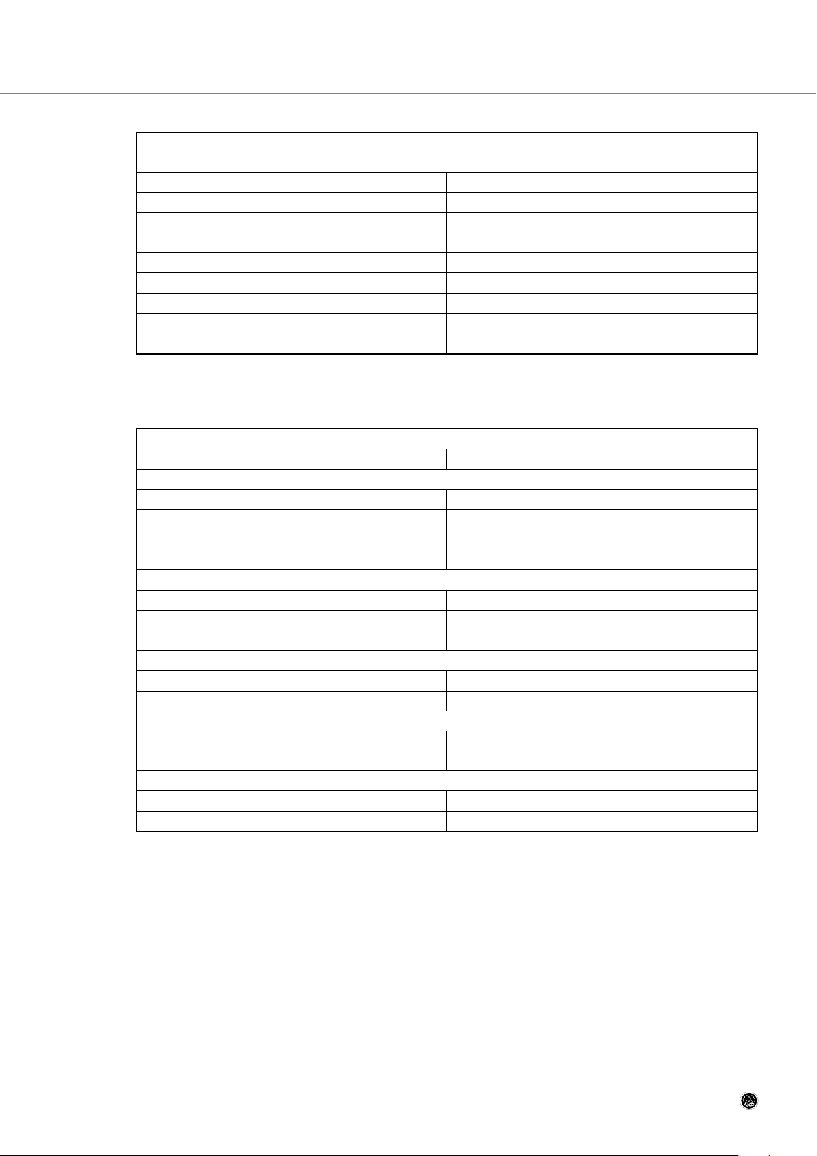
Section 9: Specifications
9.4 CS 5 PS 12
CS 5 User Manual
- 48 -
SYSTEM
8-pin RJ45
Pin no. Function
1 Data send +
2 Data send 3 Data receive +
4 48 VDC
5 48 VDC
6 Data receive 7 Ground
8 Ground
General
Efficiency 85% typical at 230 VAC & 100% load
Input
Input voltage 90-264 VAC
Input frequency 47-63 Hz
Input current 1.85 A max
Power factor Compliant with EN61000-3-2
Output
Output voltage 48 V
Output power 72 W
Short circuit protection Continuous
Environmental
Operating temperature 0°C to +65°C
Storage temperature -20 °C to +85 °C
Safety
Safety approvals EN60950-1, UL60950-1,
CAN/CSA C22.2 No. 60950 cUL
Dimensions
Width x depth x height 2.29 (58.0) x 5.20 (132.0) x 1.18 (30.0) in. (mm)
Weight 0.77 (350) lbs. (g)
Page 49
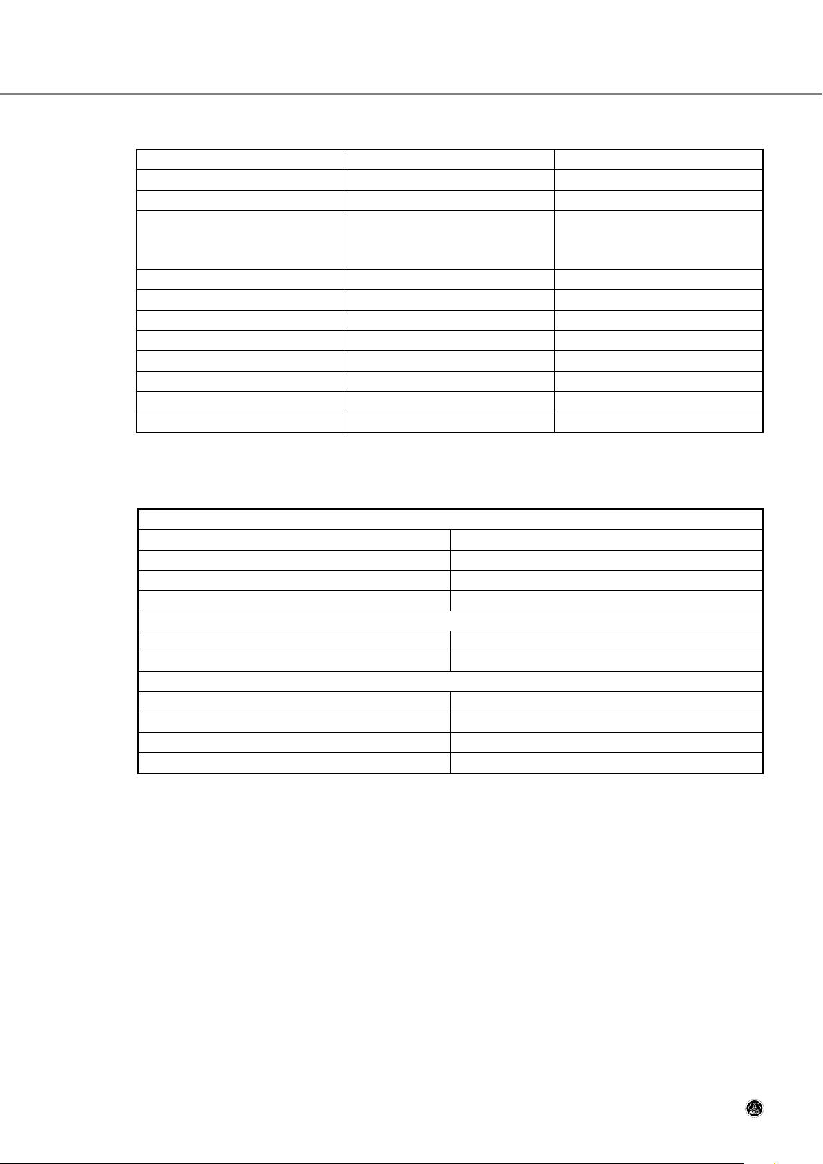
Section 9: Specifications
9.5 CS 5 IRT 1 and CS 5 IRT 2
9.6 CS 5 IRR 7
CS 5 User Manual
- 49 -
CS 5 IRT 1 CS 5 IRT 2
IN 0-5 V / 50 ohms 0-5 V / 50 ohms
OUT 0-5 V / 50 ohms 0-5 V / 50 ohms
Power voltage 200-240V 50/60Hz, 1.5A
or 100-120V 50/60Hz, 3.15A
(internally selectable)
200-240V 50/60Hz, 1.5A
or 100-120V 50/60Hz, 3.15A
(internally selectable)
Wavelength 870 nm 870 nm
Radiated power 2.5 W 3.8 W
Coverage angle (50% down) ±22 degrees ±22 degrees
Coverage area 6,450 sq.ft. / 600 m
2
10,750 sq.ft. / 1000 m
2
Width 10.3 in. / 264 mm 10.3 in. / 264 mm
Height 6.3 in. / 160 mm 12.1 in. / 307 mm
Depth 3.0 in. / 77 mm 3.0 in. / 77 mm
Weight 5.6 lbs. / 2.5 kg 8.9 lbs. / 4 kg
General
Number of channels 7
Receiving angle 140 degrees
Power supply 280 mAh, 9 V NiMH rechargeable battery
Battery life 13 hours min
Headphone Output
Rated output power into 32 ohms 9 mW
Load impedance 32 ohms min
Physical Dimensions
Height 5.3 in. / 136 mm
Width 2.7 in. / 70 mm
Depth 1.1 in. / 28 mm
Weight 4.9 oz. / 140 g
Page 50

Section 9: Specifications
9.7 CS 5 CU 50
9.8 Conformity
This product conforms to the standards listed in the related Declaration of Conformity. To order a free copy of the Declaration of Conformity for this product, visit http://www.akg.com or contact sales@akg.com.
CS 5 User Manual
- 50 -
General
Number of charging/storage slots 50
Charging modes Quick or trickle charging, automatically selected
Power supply 230 VAC, 15 VDC, 4.6 A
Quick Charging Mode
Charging current 80 mA, continuous
Trickle Charging Mode
Charging current 4 mA (avg.), pulsed
Physical Dimensions
Height 7.5 in. / 190 mm
Width 23 in. / 585 mm
Depth 19 in. / 483 mm
Weight 3.1 lbs. / 14 kg
Page 51

Mikrofone · Kopfhörer · Drahtlosmikrofone · Drahtloskopfhörer · Kopfsprechgarnituren · Akustische Komponenten
Microphones · Headphones · Wireless Microphones · Wireless Headphones · Headsets · Electroacoustical Components
Microphones · Casques HiFi · Microphones sans fil · Casques sans fil · Micros-casques · Composants acoustiques
Microfoni · Cuffie HiFi · Microfoni senza filo · Cuffie senza filo · Cuffie-microfono · Componenti acustici
Micrófonos · Auriculares · Micrófonos inalámbricos · Auriculares inalámbricos · Auriculares con micrófono · Componentes acústicos
Microfones · Fones de ouvido · Microfones s/fios · Fones de ouvido s/fios · Microfones de cabeça · Componentes acústicos
Technische Änderungen vorbehalten. Specifications subject to change without notice. Ces caractéristiques sont susceptibles de modifications.
Ci riserviamo il diritto di effettuare modifiche tecniche. Nos reservamos el derecho de introducir modificaciones técnicas. Especificações sujeitas
a mudanças sem aviso prévio.
AKG Acoustics GmbH
Lemböckgasse 21–25, A-1230 Vienna/AUSTRIA, phone: (+43-1) 86654-0*
e-mail: sales@akg.com
For other products and distributors worldwide visit www.akg.com
10/09/9100 U 13150
 Loading...