

Page 1
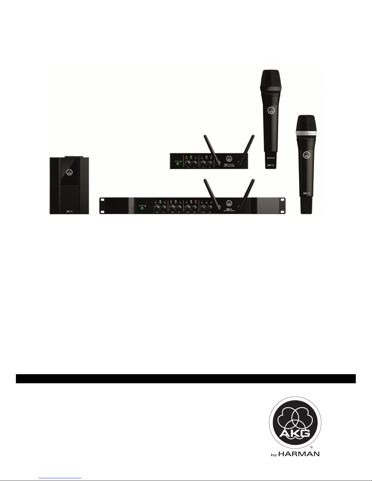
DMS 70 Quattro/Dual
BEDIENUNGSANLEITUNG ...................... 2
Bitte vor Inbetriebnahme des Gerätes lesen!
USER INSTRUCTIONS .......................... 22
Please read the manual before using the equipement!
MODE D’EMPLOI ................................. 42
Veuillez lire cette notice avant d’utiliser le système!
MODO DE EMPLEO.............................. 62
¡Sirvase leer el manual antes de utilizar el equipo!
INSTRUÇÕES DE USO .......................... 82
Favor leia este manual antes de usar o equipamento!
Page 2

Table of Contents
22 DMS 70
DMS 70DMS 70
DMS 70 Quattro/Dual
1 Safety and Environment........................................................................................... 23
Safety ........................................................................................................................ 23
Environment .............................................................................................................. 23
2 Description ............................................................................................................... 24
Introduction ............................................................................................................... 24
Scope of supply ......................................................................................................... 24
Optional Accessories .................................................................................................. 24
DSR 70 Dual receiver ................................................................................................. 24
DSR 70 Quattro receiver ............................................................................................. 24
Front panel .......................................................................................................... 25
Rear panel ........................................................................................................... 26
DHT 70 handheld transmitter ...................................................................................... 27
Controls ............................................................................................................... 27
DHT 70 Perception handheld transmitter ..................................................................... 28
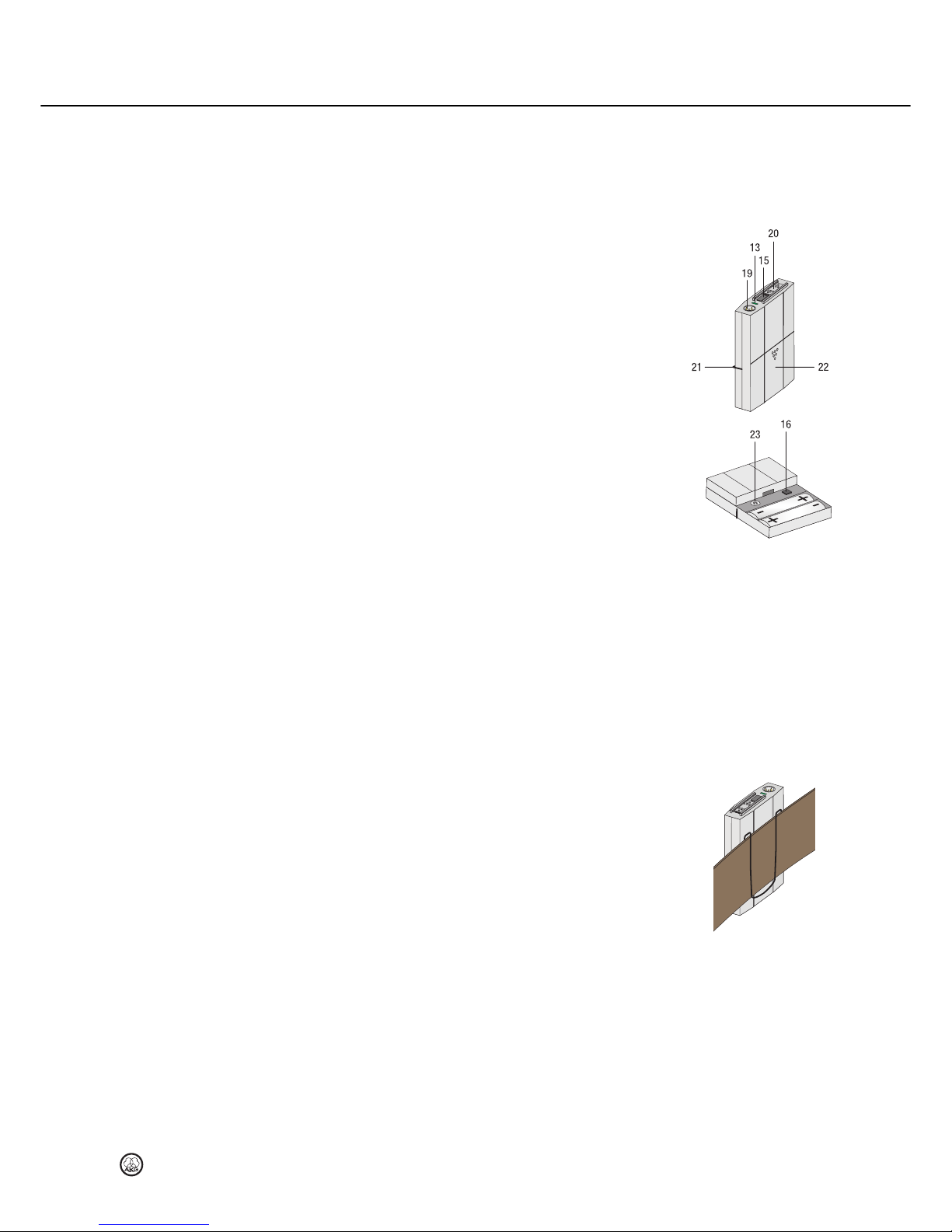
DPT 70 bodypack transmitter ...................................................................................... 29
Controls ............................................................................................................... 29
Microphones, guitar cables ................................................................................... 30
3 Installation and Connection ..................................................................................... 31
Positioning the receiver .............................................................................................. 31
Rack assembly ........................................................................................................... 31
Connecting the receiver to power ................................................................................ 31
Connecting the audio outputs of the DSR 70 Quattro receiver ....................................... 32
Connecting the receiver to a balanced input ........................................................... 32
Connecting the receiver to a speaker ..................................................................... 32
Connecting the DSR 70 Dual receiver to a balanced input ............................................. 32
4 Setting up ................................................................................................................ 33
Setting up the receiver ............................................................................................... 33
Inserting and testing batteries in the handheld transmitter DHT 70 ................................ 33
Inserting and testing batteries in the bodypack DPT 70 transmitter ................................ 33
Identifying the channel and/or appliance ...................................................................... 34
Assign the transmitter to a free channel or change the channel ..................................... 34
Registering a new transmitter on the receiver............................................................... 34
Setting up the handheld transmitter ............................................................................. 35
Setting up the bodypack transmitter ............................................................................ 35
Connecting a microphone ..................................................................................... 35
Connecting an instrument ..................................................................................... 36
Adjusting the audio level on the receiver ...................................................................... 36
Adjusting internal error correction ............................................................................... 36
Switching off DMS 70 System ..................................................................................... 36
5 Microphone technique ............................................................................................. 37
DHT 70 handheld transmitter ...................................................................................... 37
Working distance and proximity effect ................................................................... 37
Angle of incidence ................................................................................................ 37
Feedback ............................................................................................................. 37
Backing vocals ..................................................................................................... 37
DPT 70 bodypack transmitter ...................................................................................... 38
CK97 lavalier microphone ..................................................................................... 38
C 544 L headset microphone ................................................................................ 38
Putting on the microphone .................................................................................... 38
Windshield ........................................................................................................... 38
Moisture shield .................................................................................................... 38
6 Cleaning ................................................................................................................... 39
Internal windshield of handheld transmitter .................................................................. 39
7 Troubleshooting ....................................................................................................... 40
8 Specifications .......................................................................................................... 41
Table of Contents
Page 3

Safety and Environment
DMS 70
DMS 70DMS 70
DMS 70
Quattro/Dual
23
• Do not spill any liquids on the equipment.
• The equipment must only be used in dry rooms.
• The equipment must only be opened, serviced, and repaired by authorised personnel. The
equipment contains no user-serviceable parts.
• Before connecting the equipment to power, check that the AC mains voltage stated on the
supplied AC adapter is identical to the AC mains voltage available where you will use the
equipment.
• Only operate the equipment with the supplied AC adapter with a 12-VDC output. Using
adapters with a different output voltage or current type may cause serious damage to the
unit.
• If any solid object or liquid should get into the equipment, shut down the system
immediately. Disconnect the AC adapter from the power outlet at once and have the
equipment checked by our customer service department.
• If the equipment is not going to be used for a long time, disconnect the AC adapter from
the power outlet. Please note that if you turn the equipment off while leaving the AC
adapter plugged in, it is not fully isolated from the power supply.
• Do not place the equipment near heat sources such as radiators, heating ducts, amplifiers,
etc. and do not expose it to direct sunlight, excessive dust, moisture, rain, mechanical
vibrations, or shock.
• To avoid hum or interference, route all audio lines, particularly those connected to the
microphone inputs, away from power lines of any type. If you use cable ducts, be sure to
use separate ducts for the audio lines.
• Clean the equipment with a moistened (not wet) cloth only. Be sure to disconnect the AC
adapter from the power outlet before cleaning the equipment. Never use caustic or
scouring cleaners or cleaning products containing alcohol or solvents since these may
damage the enamel and plastic parts.
• Only use the equipment for the applications described in this manual. AKG cannot accept
any liability for damages resulting from improper handling or misuse.
• The power supply unit consumes a small amount of electricity even when the unit is
switched off. To save energy, unplug the power supply unit from the socket if you are not
going to be using the unit for some time.
• The packaging is recyclable. Dispose of the packaging in an appropriate recycling
collection system.
• If you scrap the unit, separate the case, electronics and cables and dispose of all the
components in accordance with the appropriate waste disposal regulations.
1 Safety and Environment
Safety
Environment
Page 4

Description
24 DMS 70
DMS 70DMS 70
DMS 70 Quattro/Dual
Thank you for purchasing an AKG product. This Manual contains important instructions for
setting up and operating your equipment. Please take a few minutes to read the instructions
below carefully before operating the equipment. Please keep the Manual for future
reference. Have fun and impress your audience!
The DMS 70 is available in five sets:
Vocal Dual Set
Vocal Dual SetVocal Dual Set
Vocal Dual Set
Instrumental Dual Set
Instrumental Dual SetInstrumental Dual Set
Instrumental Dual Set
1 DHT 70 Perception handheld
transmitter
2 AA batteries
1 tripod adapter
1 DSR 70 Dual receiver
1 SMPS switched mode power supply
3 adapters (EU/UK/US)
1 guarantee card
1 Quick Start Guide
1 DPT 70 bodypack transmitter
2 AA batteries
1 MKG L cable
1 DSR 70 Dual receiver
1 SMPS switched mode power supply
3 adapters (EU/UK/US)
1 guarantee card
1 Quick Start Guide
Vocal Quattro Set
Vocal Quattro SetVocal Quattro Set
Vocal Quattro Set
Instrumental Quattro Set
Instrumental Quattro SetInstrumental Quattro Set
Instrumental Quattro Set
Mixed Quattro Set
Mixed Quattro SetMixed Quattro Set
Mixed Quattro Set
2 DHT 70 D5 handheld transmitters
2 AA batteries
2 tripod adapters
1 DSR 70 Quattro receiver
2 rack brackets including fittings
1 SMPS switched mode power supply
3 adapters (EU/UK/US)
1 guarantee card
1 Quick Start Guide
2 DPT 70 bodypack transmitters
2 AA batteries
2 MKG L cables
1 DSR 70 Quattro receiver
2 rack brackets including fittings
1 SMPS switched mode power supply
3 adapters (EU/UK/US)
1 guarantee card
1 Quick Start Guide
1 DHT 70 D5 handheld transmitter
1 DPT 70 bodypack transmitter
2 AA batteries
1 tripod adapter
1 MKG L cable
1 DSR 70 Quattro receiver
2 rack brackets including fittings
1 SMPS switched mode power supply
3 adapters (EU/UK/US)
1 guarantee card
1 Quick Start Guide
Check that the packaging contains all of the items listed for your system. If anything is
missing, please contact your AKG dealer.
For optional accessories, refer to the current AKG catalog or folder, or visit www.akg.com.
Your dealer will be glad to help.
The DSR 70 Dual is a stationary receiver for up to 2 DMS 70-system transmitters.
The DSR 70 Dual operates within the 2.4 GHz ISM frequency range. Two DSR 70 Duals can
be used in parallel (4 channels). Communication between the receiver and the transmitter is
digital and bidirectional. Transfer is uncompressed (24 bit) and encrypted (128 bit AES).
The DSR 70 Quattro is a stationary receiver for up to 4 DMS 70-system transmitters.
The DSR 70 Quattro operates within the 2.4 GHz ISM frequency range. Two DSR 70 Quattros
can be used in parallel (8 channels). Communication between the receiver and the transmitter
is digital and bidirectional. Transfer is uncompressed (24 bit) and encrypted (128 bit AES).
NOTE
In order to ensure interference-free operation, ensure that other devices within the 2.4 GHz
range (e.g. WLAN, Bluetooth, Access Points) are switched off.
If this is not possible, you can use the AUTO CORRECTION switch (8) on the receiver to
increase the robustness of the system compared with other 2.4 GHz devices. ("Mid" or "High"
position)
2 Description
Introduction
Scope of supply
Optional Accessories
DSR 70 Dual receiver
DSR 70 Quattro receiver
Page 5
Description
DMS 70
DMS 70DMS 70
DMS 70
Quattro/Dual
25
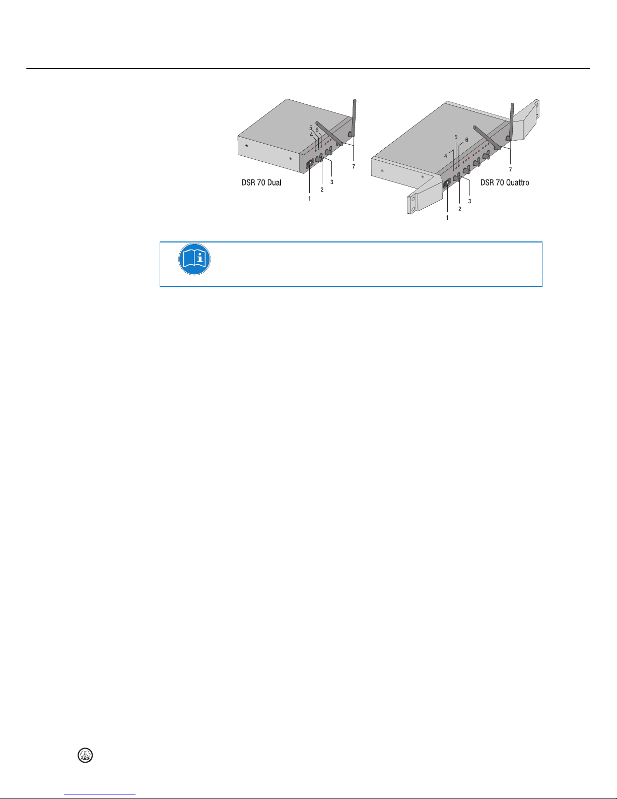
Front panel
Figure 1: Controls on the front panels of the DSR 70 Dual and Quattro receivers
NOTE
The controls (2 and 3) and the LEDs (4 to 6) are the same for all channels.
1 On/off button: This button is lit green when the receiver is switched on and ready for use. It
is sufficient to switch off the receiver to switch off the DMS 70 system. Switching off the
receiver switches off all transmitters connected to this receiver.
2 VOLUME potentiometer: This potentiometer allows continuous adjustment of the audio
output level on this channel (10/10a). The Mixing Function means that this potentiometer also
influences the sum output (9) on the DSR 70 Quattro.
3 CONNECT: This button has two functions:
Press briefly: to check the transmitters assigned to this channel.
Press and hold down (approximately 2 seconds): to assign a transmitter to a free
channel or to register a transmitter on this channel.
4 LOW BATT. LED: This LED lights up when the batteries of the transmitter registered on this
channel are flat. If the LED starts to flash red the battery will be flat within about one hour.
Replace with new batteries as soon as possible.
5 STATUS LED: This LED lights up green if a registered transmitter is active on this channel
and is ready for operation. The LED flashes green during the channel identification and
channel assignment processes.
6 CLIP LED: This LED lights up red if the audio level on this channel is too high.
7 Antennas: Fixed transmitter and receiver antennas. The best transmission and reception
performances are achieved when both antennas are pointing upwards in the "normal position"
(see diagram on the title page).
Page 6
Description
26 DMS 70
DMS 70DMS 70
DMS 70 Quattro/Dual
Rear panel
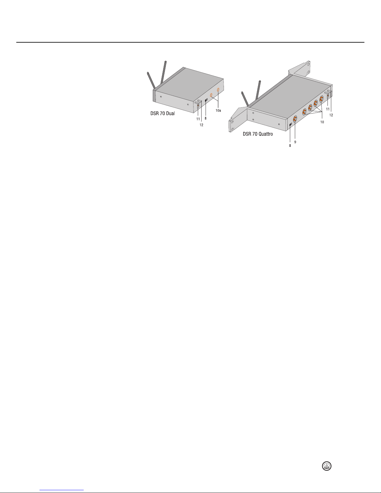
Figure 2: Controls on the rear panels of the DSR 70 Dual and Quattro receivers
8 AUTO CORRECTION switch: to adjust internal error correction.
9 Sum output/BALANCED (x1): Balanced audio output to 3-pin XLR connector. This output
transmits the combined audio signal of all 4 channels and you can connect it directly to an
active speaker.
10a CHANNEL OUT (x2): Balanced audio output to 6.35 mm jack. This output transmits the
audio signal of the respective channel. Can be connected to a microphone input on a mixer,
for example.
10 CHANNEL OUT/BALANCED (x4): Balanced audio output to 3-pin XLR connector. This
output transmits the audio signal of the respective channel. Can be connected to a
microphone input on a mixer, for example.
11 DC IN jack 12 V, 0.5 A: for connection to supplied external plug adapter.
12 Strain relief for the feeder cable of the supplied AC adapter.
Page 7
Description
DMS 70
DMS 70DMS 70
DMS 70
Quattro/Dual
27
The DHT 70 handheld transmitter operates within the 2.4 GHz ISM frequency range. The
transmitter uses two antennas integrated within the housing.
The capsule in the transmitter is the patented dynamic AKG D5 capsule with its hypercardioid
directional characteristic. It provides low handling noise sensitivity, high gain before feedback
and brilliant sound quality, as well as a built-in wind and pop filter to reduce wind and breath
noise.
Controls
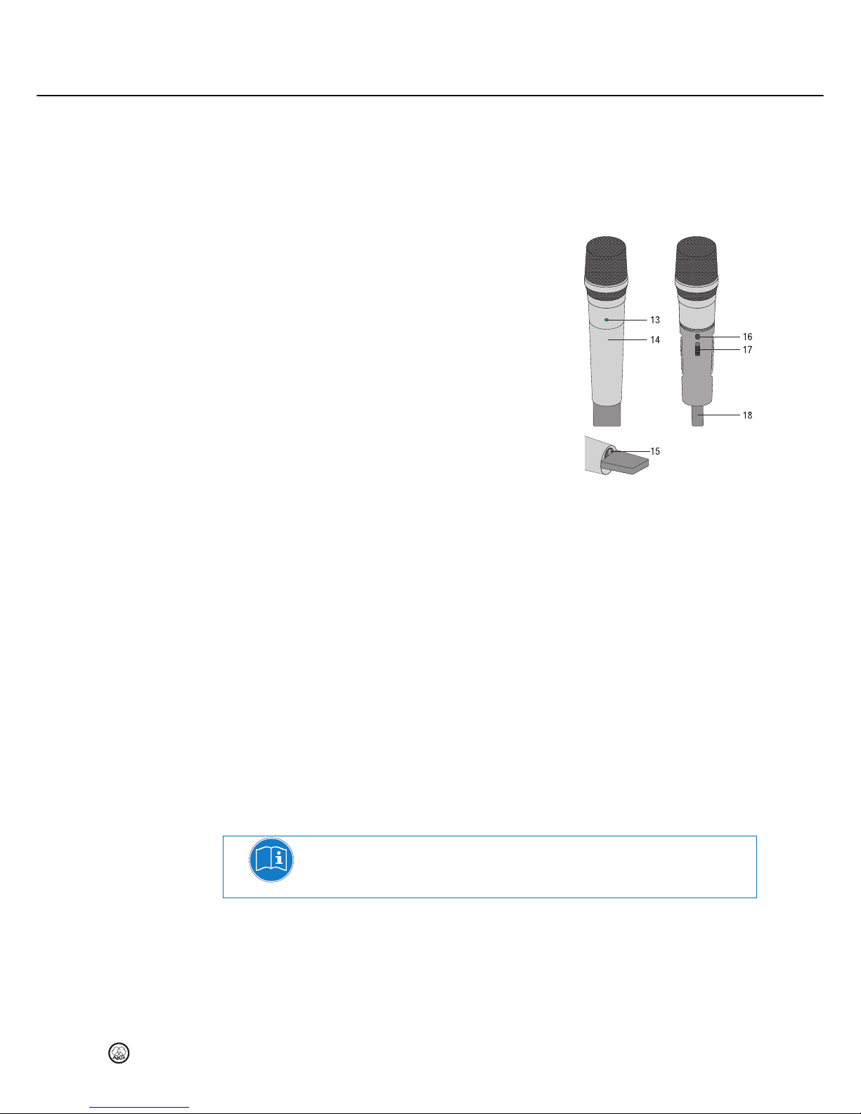
13 Status LED: Indicates the transmitter's
operating status.
LED lit green: The transmitter is
connected to the receiver
LED flashing green: No radio contact
between the transmitter and receiver
(receiver is OFF, power failure, outside
range, etc). The transmitter must be
connected to the receiver. After two
minutes without radio contact to the
receiver, the transmitter switches off
automatically.
LED lit red: From the moment the LED
changes to red, the battery capacity will
provide a maximum of one operating
hour. We recommend replacing the
batteries with new ones as soon as
possible.
14 Battery cover: See Inserting and testing batteries in the handheld transmitter
Inserting and testing batteries in the handheld transmitterInserting and testing batteries in the handheld transmitter
Inserting and testing batteries in the handheld transmitter
(see Page 33)
15 On/off button:
On: Power to the transmitter is on. The transmitter is ready for use as soon as it is
switched on.
Off (Digital Mute): Power to the transmitter is off.
16 Connect button: This button has two functions:
Press briefly: Check the assigned channel on the receiver
Press and hold down (approximately 2 seconds): Assign a free channel on the
receiver to this transmitter.
15 / 16 On/off / Connect button: Use the on/off (15) and Connect button (16) to assign this
transmitter to a free channel on the receiver.
17 GAIN switch: This slide switch allows you to set the audio input sensitivity of the
transmitter to one of two positions: "HI" = high input sensitivity, "LOW" = low input sensitivity.
18 Antenna section: The handheld transmitter has a digital diversity antenna system with two
antennas integrated within the housing.
NOTE
Do not hold the transmitter by the antenna section (18) as this will reduce the transmission
range.
DHT 70 handheld transmitter
Figure 3: Controls on DHT 70
transmitter
Page 8

Description
28 DMS 70
DMS 70DMS 70
DMS 70 Quattro/Dual
The DHT 70 Perception handheld transmitter has a dynamic standard capsule with a cardioid
directional characteristic.
The controls are identical to those on the DHT 70.
Description of the controls
controlscontrols
controls (Page 27).
DHT 70 Perception handheld transmitter
Page 9
Description
DMS 70
DMS 70DMS 70
DMS 70
Quattro/Dual
29
You can use the DPT 70 bodypack transmitter with both dynamic microphones and condenser
microphones operating on a supply voltage of approx. 4 V. Naturally you may also connect an
electric guitar, electric bass or keytar.
The DPT 70 operates within the 2.4 GHz ISM frequency range.
Controls
13 Status LED: Indicates the transmitter's operating status.
LED lit green: The transmitter is connected to the
receiver
LED flashing green: No radio contact between the
transmitter and receiver (receiver is OFF, power
failure, outside range, etc). The transmitter must be
connected to the receiver. After two minutes
without radio contact to the receiver, the transmitter
switches off automatically.
LED lit red: From the moment the LED changes to
red, the battery capacity will provide a maximum of
one operating hour. We recommend replacing the
batteries with new ones as soon as possible.
15 On/off button:
On: Power to the transmitter is on. The transmitter
is ready for use as soon as it is switched on.
Off (Digital Mute): Power to the transmitter is off.
16 Connect button: This button has two functions:
Press briefly: Check the assigned channel on the
receiver
Press and hold down (approximately 2 seconds): Assign a free channel on the
receiver to this transmitter.
15 / 16 On/off / Connect button: Use the on/off (15) and Connect button (16) to assign this
transmitter to a free channel on the receiver.
19 Audio input is a 3-pin mini-XLR connector. Automatically matches the connector pinout of
the recommended AKG microphones or optional MKG L guitar cable.
20 Cover: The sliding cover prevents the transmitter from being switched on/off inadvertently
21 Belt clip: For fixing the bodypack transmitter to your belt.
Attach the bodypack transmitter to a belt or in a pocket with
the battery compartment cover facing away from the body.
22 Battery compartment cover with integrated screwdriver.
23 GAIN control: This rotary control allows you to match the
transmitter input gain to the connected microphone or
instrument.
DPT 70 bodypack transmitter
Figure 4: Controls on DPT
70 transmitter
Figure 5: Attachment of
bodypack transmitter to belt
Page 10

Description
30 DMS 70
DMS 70DMS 70
DMS 70 Quattro/Dual
Microphones, guitar cables
The following AKG microphones can easily be connected to the audio input of the DPT 70:
• C 520 L, C 555 L, C 544, HC 577, CK 77 WR-L, CK97
• C 516 ML, C 518 ML, C 519 ML, C 411 L
• The MKG L guitar cable from AKG lets you connect an electric guitar, electric bass or
keytar to the bodypack transmitter.
The MKG L guitar cable is included in the Instrumental Set and the Mixed Set and is also
available separately as an accessory.
NOTE
Keep the microphones used at least 10 cm away from the bodypack transmitter to prevent
interference in the microphone capsule from being audible in the audio transfer.
Page 11
Installation and Connection
DMS 70
DMS 70DMS 70
DMS 70
Quattro/Dual
31
1) Always position the receiver near to where the action is taking place (e.g. stage).
2) Check that you can see the receiver from where you will be using the transmitter.
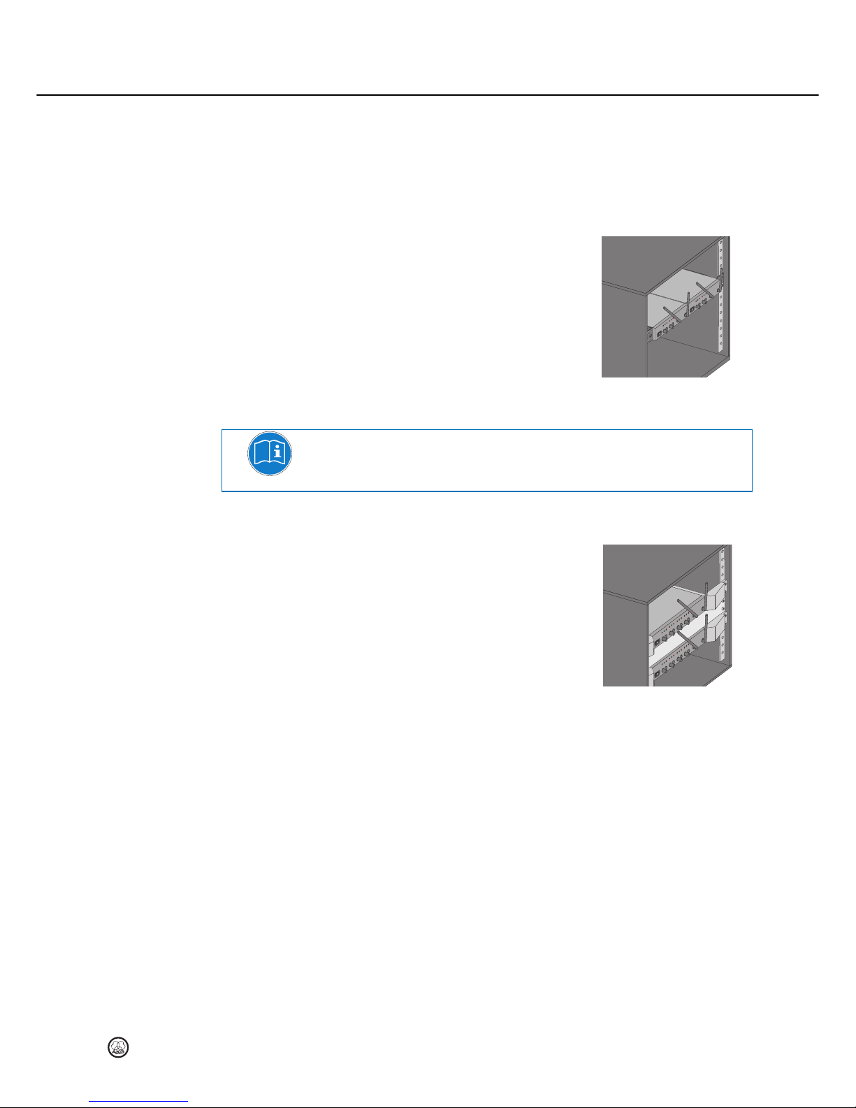
Assembling the DSR 70 Dual in a 19" rack
Figure 6: Assembling the DSR 70 Dual in a 19" rack
NOTE
For assembling one or more DSR 70 Dual receivers, the RMU 40 PRO rack assembly set is
available in the current AKG catalogue/folder or at www.akg.com.
Assembling the DSR 70 Quattro in a 19" rack
Assemble the DSR 70 Quattro receiver in your 19"
rack with the supplied rack brackets, fixing screws and
washers - these are screwed into the side of the
receiver.
1) Unscrew the fixing screws of each of the two side
walls.
2) Secure the rack brackets to the receiver using the
fixing screws.
3) Secure the receiver in the rack.
4) Rotate both antennas (7) up to the "normal
position" (see diagram on the title page) to
achieve optimum transmission and reception
performance.
Use of two receivers in one rack
1) Fit both receivers in the rack with one unit of space between them.
2) Rotate both antennas (7) up to the "normal position" (see diagram on the title page).
1) Check that the AC mains voltage stated on the included power supply is identical to the
AC mains voltage available where you will use your system. Using the power supply with
a different AC voltage may wreck the unit.
2) Plug the feeder cable of the included power supply into the 12 V, 0.5 A, DC IN socket
(11) on the receiver.
3) Connect the AC adapter to a power outlet. Ensure that you are using the correct adapter
for the country you are in.
3 Installation and Connection
Positioning the receiver
Rack assembly
Figure 7: Fitting the DSR70 in a
19" rack
Connecting the receiver to power
Page 12

Installation and Connection
32 DMS 70
DMS 70DMS 70
DMS 70 Quattro/Dual
Connecting the receiver to a balanced input
Use an XLR cable to connect the BALANCED output (10) of the required channel on the back
of the receiver to the balanced microphone input (XLR socket) on the mixer or amplifier.
Connecting the receiver to a speaker
Use an XLR cable to connect the sum output (9) of all four channels on the back of the
receiver to an active speaker.
Connect the 6.35 mm jack (10a) of the required channel on the back of the receiver to the
balanced microphone input on the mixer or amplifier.
Connecting the audio outputs of the DSR 70
Quattro receiver
Connecting the DSR 70 Dual receiver to a
balanced input
Page 13

Setting up
DMS 70
DMS 70DMS 70
DMS 70
Quattro/Dual
33
Press the On/off switch (1) to switch the receiver on. This green button is illuminated when
the receiver is ready for use.
1) Unscrew thebattery cover (14) from the handheld transmitter.
2) Lift up the two battery compartment covers.
3) Insert the supplied batteries into the battery compartment conforming to the polarity
marks.
The transmitter will not function if you insert the batteries the wrong way round.
4) Close the two battery compartment covers.
5) Switch on the transmitter with the On/Off button (15).
If the status LED (13) flashes green, the batteries are in good condition but there
is no radio contact with the receiver. The transmitter must be connected to the
receiver.
If the status LED is lit green, the batteries are in good condition and there is radio
contact between the transmitter and receiver. Speak or sing into the microphone.
If the status LED goes red the batteries are likely to be flat in approx. 1 hour.
Replace with new batteries as soon as possible.
If the status LED does not light up the batteries are flat or possibly incorrectly fitted.
Insert new batteries or insert the existing batteries correctly. Check for the correct
polarity.
6) Screw on the battery cover tightly.
1) Depress the snap hook on the battery compartment cover (22).
2) Pull the battery compartment cover down and off the transmitter.
3) Insert the supplied batteries into the battery compartment conforming to the polarity
marks.
The transmitter will not function if you insert the batteries the wrong way round.
4) Slide the slide cover (20) to the rear position and switch on the transmitter using the
on/off switch (15).
If the status LED (13) flashes green, the batteries are in good condition but there
is no radio contact with the receiver. The transmitter must be connected to the
receiver.
If the status LED is lit green, the batteries are in good condition and there is radio
contact between the transmitter and receiver.
If the status LED goes red the batteries are likely to be flat in approx. 1 hour.
Replace with new batteries as soon as possible.
If the status LED does not light up the batteries are flat or possibly incorrectly fitted.
Insert new batteries or insert the existing batteries correctly. Check for the correct
polarity.
5) Push the slide cover over the on/off switch to prevent the transmitter from being switched
on/off inadvertently.
6) To close the battery compartment, slide the battery compartment cover onto the battery
compartment from below until the snap hook engages.
4 Setting up
Setting up the receiver
Inserting and testing batteries in the
handheld transmitter DHT 70
Inserting and testing batteries in the
bodypack DPT 70 transmitter
Page 14
Setting up
34 DMS 70
DMS 70DMS 70
DMS 70 Quattro/Dual
When delivered, the transmitters are preconfigured to channels 1 and 2 of the receiver.
Use the identification function to check
the channel on the receiver assigned for a transmitter and
the connected transmitter for a channel on the receiver.
Press Connect (16) briefly on the transmitter or the receiver.
The status LEDs (13) on the same channel of the transmitter and receiver flash
green.
NOTE
This identification function can also be used during operation without causing any disturbance
or interruption.
The following instructions apply for the assignment of a free channel and for changing a
channel.
Actions 3 and 4 can be started from the transmitter and receiver. In this example, they are
started from the receiver.
1) Pull the battery compartment cover (14 / 22) down and off the transmitter.
2) Switch on the transmitter and receiver.
3) Press Connect (3) on a free channel of the receiver and hold down until the status LED
(5) starts to flash after approximately 2 seconds.
You need to confirm with the transmitter within the next 30 seconds.
4) Hold down Connect (16) on the transmitter until the status LED (13) lights up green.
The status LEDs on the transmitter (13) and the receiver (5) light up green once
assignment has been successful.
NOTE
The actuated settings are saved. This means that you can simply continue using the DNS 70
system with the last-used settings (channel assignments) the next time you switch on.
NOTE
Dual channel use is not possible with the DMS70 system.
I.e. several transmitters can't be assigned to a single channel on the receiver. The LED on the
connected transmitter lits green, the LED on the transmitter, which is not connected, flashes
green. Please assign this transmitter to a free channel on the receiver.
Take care that you do not use a channel twice.
Start the registration process with the transmitter: Transmitter -> Receiver
1) Pull the battery compartment cover (14 / 22) down and off the transmitter.
2) Switch on the receiver.
3) Press and hold Connect (16) on the transmitter while pressing the on/off button(15)
until the status LED (13) starts to flash.
Within the next 30 seconds, the status LED (13) flashes rapidly and you need to
confirm with the receiver.
4) Hold down Connect (3) on a free channel of the receiver until the status LED (5) lights
up green.
The status LEDs on the transmitter (13) and the receiver (5) light up green after
successful registration.
Identifying the channel and/or appliance
Assign the transmitter to a free channel or
change the channel
Registering a new transmitter on the
receiver
Page 15
Setting up
DMS 70
DMS 70DMS 70
DMS 70
Quattro/Dual
35
You can also start this process from the receiver: Receiver -> Transmitter
1) Pull the battery compartment cover (14 / 22) down and off the transmitter.
2) Switch on the receiver.
3) Press Connect (3) on a free channel of the receiver and hold down until the status LED
(5) starts to flash after approximately 2 seconds.
You need to confirm with the transmitter within the next 30 seconds.
4) Press and hold Connect (16) on the transmitter while pressing the on/off button(15)
until the status LED (13) lights up green.
The status LEDs on the transmitter (13) and the receiver (5) light up green after
successful registration.
1) Switch on the handheld transmitter using the on/off button (15).
2) Switch on your PA system or amplifier.
3) Assign the handheld transmitter and receiver to a free channel.
4) Speak or sing into the microphone and watch the CLIP LED (6) on the receiver:
Set the GAIN switch (17) to "HIGH" under normal conditions.
If the CLIP LED lights up frequently or all the time when you sing loudly, the input
sensitivity of the transmitter is too high. Set the GAIN to "LOW".
5) Set the volume of the PA system or amplifier referring to the appropriate instruction
manual or by ear.
NOTE
After two minutes without radio contact with the receiver (receiver is OFF, power failure, outside
range, etc) the connected transmitters switch off automatically.
The bodypack transmitter DPT 70 has been designed for use with the CK 55 L, C 411 L, C
520 L, C 555 L, C 516 ML, C 518 ML, C 519 ML and CK 77 WR-L microphones from AKG.
If you wish to connect microphones from other manufacturers to the DPT 70, please note that
you may have to replace the existing connector of your microphone with a 3-pin mini XLR
connector.
Audio input pinout:
Pin 1: shield
Pin 2: audio inphase (+)
Pin 3: supply voltage
A 4V positive supply voltage for condenser microphones is available on pin 3.
ATTENTION
There is no guarantee that the bodypack transmitter DPT 70 will work perfectly with products
from other manufacturers. Any damage that may result from such use is not covered by the
AKG warranty scheme.
Connecting a microphone
1) Remove the battery compartment cover (22).
2) Plug the mini XLR connector on the cable of your microphone into the audio input
socket (19) on the bodypack transmitter.
3) Slide the slide cover (20) to the rear position and switch on the bodypack transmitter
using the on/off switch (15).
4) Assign a free channel to the bodypack transmitter and receiver.
5) Speak or sing into the microphone.
6) Use the screwdriver integrated in the battery compartment cover to set the GAIN control
(23) to a position where the CLIP LED (6) on the receiver will flash occasionally.
7) Replace the battery compartment cover on the transmitter.
Setting up the handheld transmitter
Setting up the bodypack transmitter
Page 16

Setting up
36 DMS 70
DMS 70DMS 70
DMS 70 Quattro/Dual
Connecting an instrument
1) Remove the battery compartment cover (22).
2) Plug the jack plug on the MKG L guitar cable into the output jack of your instrument and
the mini XLR connector on the guitar cable into the audio input socket (19) of the
bodypack transmitter.
3) Slide the slide cover (20) to the rear position and switch on the bodypack transmitter
using the on/off switch (15).
4) Assign a free channel to the bodypack transmitter and receiver.
5) Play your instrument.
6) Use the screwdriver integrated in the battery compartment cover to set the GAIN control
(23) to a position where the CLIP LED (6) on the receiver will flash occasionally.
7) Replace the battery compartment cover on the transmitter.
Use the VOLUME potentiometer (2) to adjust the audio output level on this channel (10/10a).
Connect the DSR 70 Quattro receiver to an active speaker and use the VOLUME
potentiometers of the active channels to adjust the sum output (9) based on the Mixing
Function.
In an undisturbed environment, set the AUTO CORRECTION switch (8) on the back of the
receiver to "Low" which guarantees an optimum transfer time.
If another interfering device in the 2.4 GHz ISM frequency range causes unwanted signals
near the receiver, this can cause interference. Increase the internal error correction by
adjusting the AUTO CORRECTION switch to the "Mid" or "High" setting.
It is sufficient to switch off the receiver to switch off the DMS 70 system. The receiver
switches off all transmitters connected to it.
Adjusting the audio level on the receiver
Adjusting internal error correction
Switching off DMS 70 System
Page 17

Microphone technique
DMS 70
DMS 70DMS 70
DMS 70
Quattro/Dual
37
A handheld vocal microphone provides many ways of shaping the sound of your voice as it is
heard over the sound system.
The following sections contain useful hints on how to use your DHT 70 handheld transmitter
for best results.
Working distance and proximity effect
Basically, your voice will sound bigger and mellower, the closer you hold the microphone to
your lips. Moving away from the microphone will produce a more reverberant, more distant
sound as the microphone will pick more of the room’s reverberation.
You can use this effect to make your voice sound aggressive, neutral, sensual, etc. simply by
altering your distance from the microphone.
The proximity effect is a powerful increase in low frequency response that occurs when a
sound source is close to a microphone (less than 2 inches / 5 cm). It gives more "body" to
your voice and an intimate, bass-heavy sound.
Angle of incidence
Sing to one side of the microphone or above and across the top of the microphone. This
provides a well-balanced, natural sound.
If you sing directly into the microphone, it will not only pick up excessive breath noise but also
overemphasise "s", "sh", "tch", "p", and "t" sounds.
Feedback
Feedback occurs when part of the sound projected by the loudspeakers is picked up by a
microphone, amplified and fed back to the speakers. Above a certain volume (the feedback
threshold) this process becomes a vicious circle, making the sound system howl and screech.
The only solution is to turn down the volume.
To reduce the danger of this happening, the microphone of the DHT 70 has a cardioid pickup
pattern.
This means that the microphone is most sensitive to sounds arriving from in front of it (your
voice), while picking up hardly any sound arriving from the sides or rear (from monitor
speakers for instance).
To maximize gain before feedback, place the PA speakers in front of the microphones (along
the front edge of the stage).
If you use monitor speakers, be sure never to point any microphone directly at the monitors or
at the PA speakers.
Feedback may also be triggered by resonances (due to the room acoustics), particularly in the
low frequency range, and thus indirectly by the proximity effect. In this case, it is often enough
to move away from the microphone a little to stop the feedback.
Backing vocals
1) Never let more than two people share a microphone.
2) Backing vocalists should not sing at more than 35° to the microphone axis.
The microphone is very insensitive to sounds arriving from the side. If the two vocalists
were to try and sing into the microphone at an angle of more than 35° to the microphone
axis, you would have to turn up the level of the microphone channel high enough to cause
a feedback problem.
5 Microphone technique
DHT 70 handheld transmitter
Page 18
Microphone technique
38 DMS 70
DMS 70DMS 70
DMS 70 Quattro/Dual
CK97 lavalier microphone
Fix the microphone to the supplied lavalier clip or to the optional H 41/1 tiepin.
1) Clip the microphone onto the speaker's clothing, as close as possible to his or her
mouth.
NOTE
The closer the microphone is to the speaker's mouth, the less danger there is of feedback.
2) Make sure to aim the microphone towards the user's mouth.
C 544 L headset microphone
Putting on the microphone
1) Put the microphone on.
2) Bend the gooseneck so that the microphone sits to one side in front of the corner of your
mouth.
NOTE
• If you hear excessive pop noise ("p" and "t" sounds are overemphasised unnaturally),
move the microphone capsule further away from your mouth (back or down).
• If the microphone sounds "thin" or flat, move the microphone capsule closer to your
mouth.
• Find the optimum position during the soundcheck.
Windshield
If (for instance,on an open-air stage) excessive wind or pop noise becomes audible, attach the
supplied foam windshield to the microphone.
1) Slide the windshield onto the microphone capsule.
2) Pull the windshield over the outer end of the microphone capsule.
Moisture shield
A special moisture shield on the microphone capsule makes it harder for moisture and
makeup to penetrate into the microphone.
This prevents the microphone apertures from being clogged by perspiration or makeup, which
would make the sound dull and reduce the sensitivity of the microphone. Therefore, you
should never remove the moisture shield from the microphone.
The C 544 L headset microphone includes a replacement moisture shield in case the first one
gets damaged or lost.
DPT 70 bodypack transmitter
Page 19

Cleaning
DMS 70
DMS 70DMS 70
DMS 70
Quattro/Dual
39
Unplug the power supply unit from the socket.
Clean the surface of the unit with a moistened (not wet) cloth.
ATTENTION
Never use caustic or scouring cleaners or cleaning agents containing alcohol or solvents, since
these may damage the enamel and plastic parts.
1) Unscrew and remove the wire-mesh cap of the handheld transmitter.
2) Take the windshield (foam insert) out of the wire-mesh cap.
3) Wash the windshield in mild soap suds.
4) As soon as the windshield has dried, replace it in the wire-mesh cap and screw the wire-
mesh cap onto the handheld transmitter.
6 Cleaning
Internal windshield of handheld transmitter
Page 20
Troubleshooting
40 DMS 70
DMS 70DMS 70
DMS 70 Quattro/Dual
Problem
ProblemProblem
Problem
Possible cause
Possible causePossible cause
Possible cause
Remedy
RemedyRemedy
Remedy
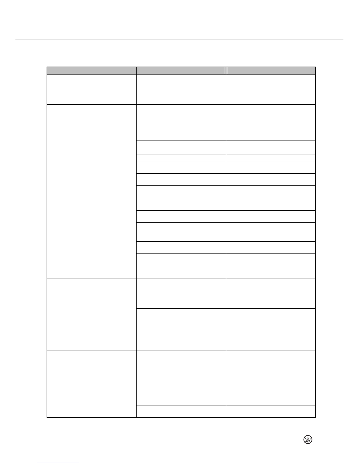
No radio contact, the status LED (13) on the
transmitter is flashing green.
The connected transmitters switch off
automatically after two minutes without radio
contact with the receiver.
The receiver is switched off, there is a power
failure, the transmitter is out of range, or a
new transmitter is not registered.
Set up the receiver. Make sure the transmitter
is in range of the transmitter.
No sound
No sound because dual channel usage is not
permitted. Status LED (13) of the transmitter
flashes green, because another transmitter is
active on the same channel on the receiver.
Channel identification is not possible if
transmitter is not connected.
Switch off the transmitter which is not
outputting an audio signal and assign this
transmitter to a free channel on the receiver.
AC adapter is not connected to receiver
and/or power outlet.
Connect AC adapter to receiver and/or power
outlet.
Receiver is OFF. Switch on receiver using on/off button (1).
Receiver is not connected to mixer or
amplifier.
Connect receiver output to mixer or amplifier
input.
VOLUME potentiometer (2) on receiver is at
zero.
Turn up VOLUME potentiometer
Microphone or instrument is not connected to
bodypack transmitter.
Connect microphone or instrument to audio
input (19) on bodypack.
Transmitter on/off switch (15) is set to "OFF"
or "MUTE".
Set transmitter on/off switch to "ON".
Transmitter batteries are not inserted
properly.
Insert batteries conforming to "+" and "-"
marks.
Transmitter batteries are flat. Replace transmitter batteries.
Transmitter is too far away from the receiver. Move closer to the receiver.
Obstructions between transmitter and
receiver.
Remove obstructions.
No line of sight between transmitter and
receiver.
Avoid spots where you cannot see receiver.
Receiver is too close to metal objects. Remove interfering objects or move receiver
away from them.
Noise, crackling, unwanted signals
Antenna is in an unsuitable position. Move receiver to a different location. The best
transmission and reception performance is
achieved when the antennas (7) are pointing
upwards in the "normal position" (see
diagram on the title page).
Interference from other wireless systems, TV,
radio, mobile phone, walkie-talkies, or
defective electrical appliances or installations.
Increase the internal error correction by
adjusting the AUTO CORRECTION switch to
the "Mid" or "High" setting.
Switch off interfering appliances within the
2.4 GHz ISM frequency range; switch off
defective appliances; have electrical
installations checked.
Distortion
GAIN control (17 / 23) is set too high or too
low.
Turn GAIN control up or down until distortion
goes away.
Interference from other wireless systems, TV,
radio, mobile phone, walkie-talkies, or
defective electrical appliances or installations.
Increase the internal error correction by
adjusting the AUTO CORRECTION switch to
the "Mid" or "High" setting.
Switch off interfering appliances within the
2.4 GHz ISM frequency range; switch off
defective appliances; have electrical
installations checked.
Antenna position. Move receiver to a different location. If dead
spots persist, mark and avoid them.
7 Troubleshooting
Page 21
Specifications
DMS 70
DMS 70DMS 70
DMS 70
Quat
tro/Dual
41
DSR 70 Dual
DSR 70 DualDSR 70 Dual
DSR 70 Dual
DHT 70 Perceptio
DHT 70 PerceptioDHT 70 Perceptio
DHT 70 Perceptio
nnnn
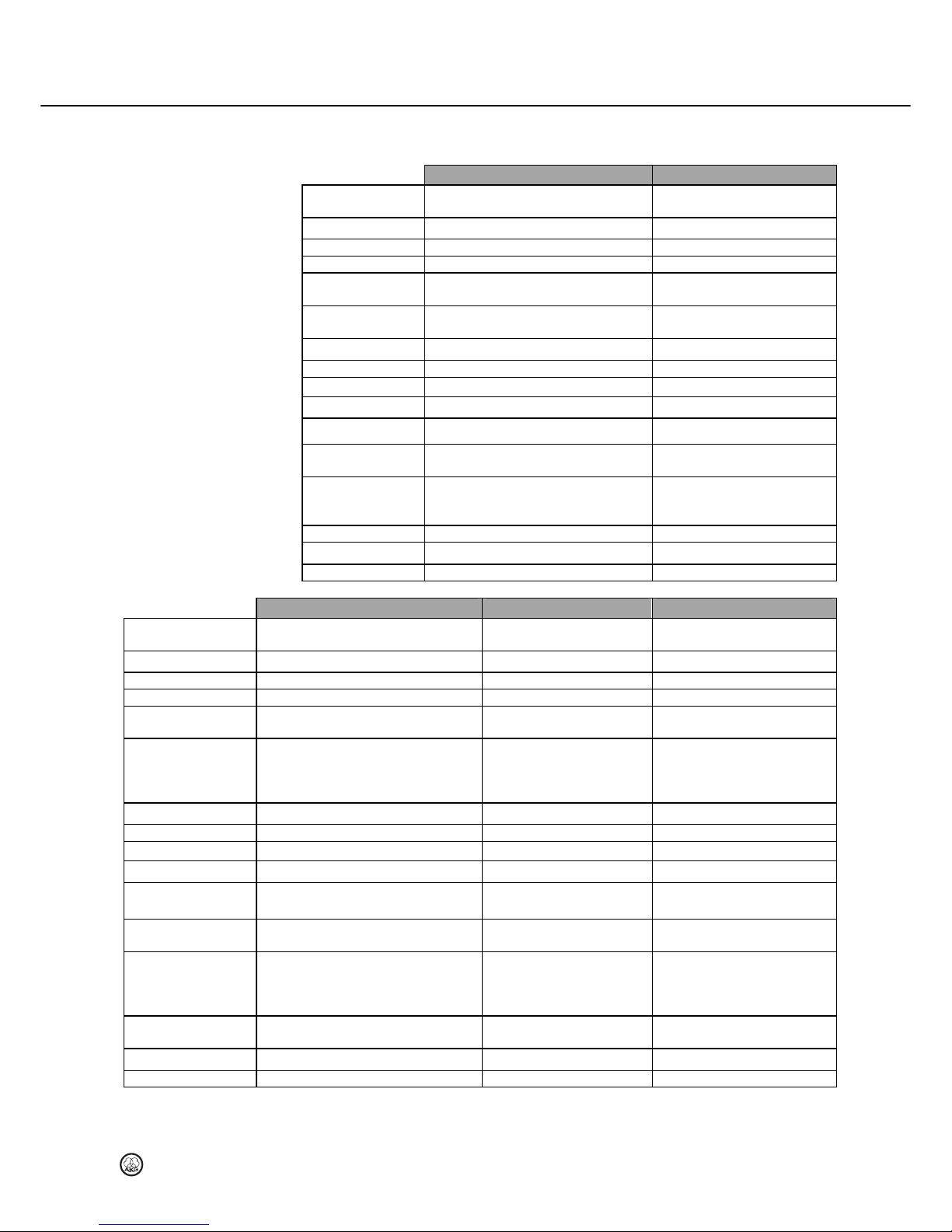
Carrier frequency
range
DFS (dynamic frequency selection) in 2.4
GHz ISM band
DFS in 2.4 GHz ISM band
Switching bandwidth DFS DFS
RF output max. 100 mW max. 100 mW
Diversity System Digital diversity Digital diversity
Modulation /
bandwidth
OFDM (Orthogonal Frequency-Division
Multiplexing) 16 MHz
OFDM 16 MHz
GAIN control 0 – 1.4 Vrms
max. SPL:
≤
142 dB (GAIN = LOW)
max. SPL: ≤ 129 dB (GAIN = HIGH)
Frequency response 20 – 20,000 Hz (± 1 dB) 70 – 16,000 Hz (± 3 dB)
T.H.D.
≤
0.05%
≤
0.05%
Overall dynamic range 120 dB(A) 113 dB(A)
Encryption 128 Bit AES 128 Bit AES
Audio outputs 2 x 6.35mm jack -
Range Indoor 30 m NLOS
Outdoor 50 m LOS
Indoor 30 m NLOS
Outdoor 50 m LOS
Power requirement 12 Vdc, 0.5 A ~ 6 hours: 2x LR6 AA alkaline
batteries
~ 7 hours: 2x AA NiMH batteries
Dimensions Standalone: 202 mm × 45 mm × 125 mm 233 mm x 51 mm
Net weight 480 g 260 g
Microphone capsule - Hypercardioid
DSR 70 Quattro
DSR 70 QuattroDSR 70 Quattro
DSR 70 Quattro
DPT 70
DPT 70DPT 70
DPT 70
DHT 70 D5
DHT 70 D5DHT 70 D5
DHT 70 D5
Carrier frequency range DFS (dynamic frequency selection) in 2.4
GHz ISM band
DFS in 2.4 GHz ISM band DFS in 2.4 GHz ISM band
Switching bandwidth DFS DFS DFS
RF output max. 100 mW max. 100 mW max. 100 mW
Diversity System Digital diversity Digital diversity Digital diversity
Modulation / bandwidth OFDM (Orthogonal Frequency-Division
Multiplexing) 16 MHz
OFDM 16 MHz OFDM 16 MHz
GAIN control 0 – 1.4 Vrms 0 (2.2 Vrms) – 30 dB
(70 mVrms)
max. input-level: > 3 Vrms
(GAIN = MIN)
max. SPL:
≤
142 dB (GAIN = LOW)
max. SPL: ≤ 129 dB (GAIN = HIGH)
Frequency response 20 – 20,000 Hz (± 1 dB) 30 – 20,000 Hz (± 1 dB) 70 – 20,000 Hz (± 3 dB)
T.H.D.
≤
0.05%
≤
0.05%
≤
0.05%
Overall dynamic range 120 dB(A) 125 dB(A) 120 dB(A)
Encryption 128 Bit AES 128 Bit AES 128 Bit AES
Audio outputs 5 x XLR balanced,
(4x channel, 1x sum)
- -
Range Indoor 30 m NLOS
Outdoor 50 m LOS
Indoor 30 m NLOS
Outdoor 50 m LOS
Indoor 30 m NLOS
Outdoor 50 m LOS
Power requirement 12 Vdc, 0.5 A ~ 6 hours: 2x LR6 AA alkaline
batteries
~ 7 hours: 2x AA NiMH
batteries
~ 6 hours: 2x LR6 AA alkaline
batteries
~ 7 hours: 2x AA NiMH batteries
Dimensions Standalone: 303 mm × 42 mm × 144 mm
Rack: 482 mm × 42 mm × 144 mm
92 mm × 64 mm x 28 mm 233 mm x 51 mm
Net weight 1180 g 70 g 260 g
Microphone capsule - - Dynamic hypercardioid - D 5
This product conforms to the standards listed in the Declaration of Conformity. To order a free
copy of the Declaration of Conformity, visit http://www.akg.com or contact [email protected].
8 Specifications
Page 22

Technische Änderungen vorbehalten. Specifications subject to change without notice. Ces caractéristiques sont susceptibles de modifications. Ci
riserviamo il diritto di effettuare modifiche tecniche. Nos reservamos el derecho de introducir modificaciones técnicas. Especificações sujeitas a
mudanças sem aviso prévio.
02/12/9100 U 13970_B
Mikrofone · Kopfhörer · Drahtlosmikrofone · Drahtloskopfhörer · Kopfsprechgarnituren · Akustische Komponenten
Microphones · Headphones · Wireless Microphones · Wireless Headphones · Headsets · Electroacoustical Components
Microphones · Casques HiFi · Microphones sans fil · Casques sans fil · Micros-casques · Composants acoustiques
Microfoni · Cuffie HiFi · Microfoni senza filo · Cuffie senza filo · Cuffie-microfono · Componenti acustici
Micrófonos · Auriculares · Micrófonos inalámbricos · Auriculares inalámbricos · Auriculares con micrófono · Componentes acústicos
Microfones · Fones de ouvido · Microfones s/fios · Fones de ouvido s/fios · Microfones de cabeça · Componentes acústicos
AKG Acoustics GmbH
Lemböckgasse 21–25, A-1230 Vienna/AUSTRIA, phone: (+43-1) 86654-0*
e-mail: [email protected]
For other products and distributors worldwide visit www.akg.com
 Loading...