

Page 1
Bedienungshinweise . . . . . . . . . . . . . . . . . . S. 2
Bitte vor Inbetriebnahme des Gerätes lesen!
User Instructions . . . . . . . . . . . . . . . . . . . . p. 18
Please read the manual before using the equipment!
Mode d’emploi . . . . . . . . . . . . . . . . . . . . . . p. 34
Veuillez lire cette notice avant d’utiliser le système!
Istruzioni per l’uso . . . . . . . . . . . . . . . . . . . p. 50
Prima di utilizzare l’apparecchio, leggere il manuale!
Modo de empleo . . . . . . . . . . . . . . . . . . . . p. 66
Antes de utilizar el equipo, lea por favor el manual!
Instruções de uso . . . . . . . . . . . . . . . . . . . p. 82
Por favor leia este manual antes de usar o equipamen
to!
C 416
III
Page 2
2
1 Sicherheitshinweis/Beschreibung
1.1 Sicherheitshinweis
1.2
Lieferumfang
1.3 Empfohlenes
Zubehör
Überprüfen Sie bitte, ob das Gerät, an das Sie das
Mikrofon anschließen möchten, den gültigen Sicherheitsbestimmungen entspricht und mit einer
Sicherheitserdung versehen ist.
Kontrollieren Sie bitte, ob die Verpackung alle
oben angeführten Teile enthält. Falls etwas fehlt,
wenden Sie sich bitte an Ihren AKG-Händler.
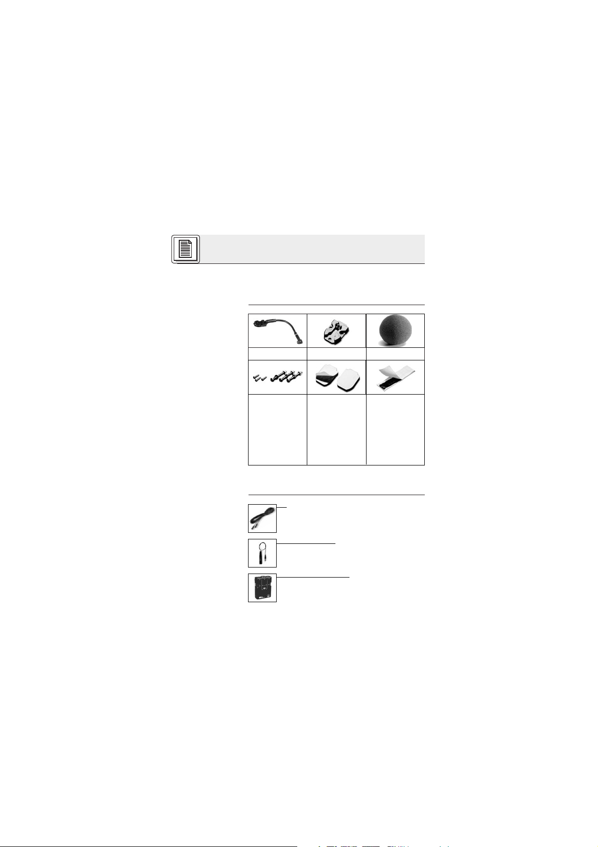
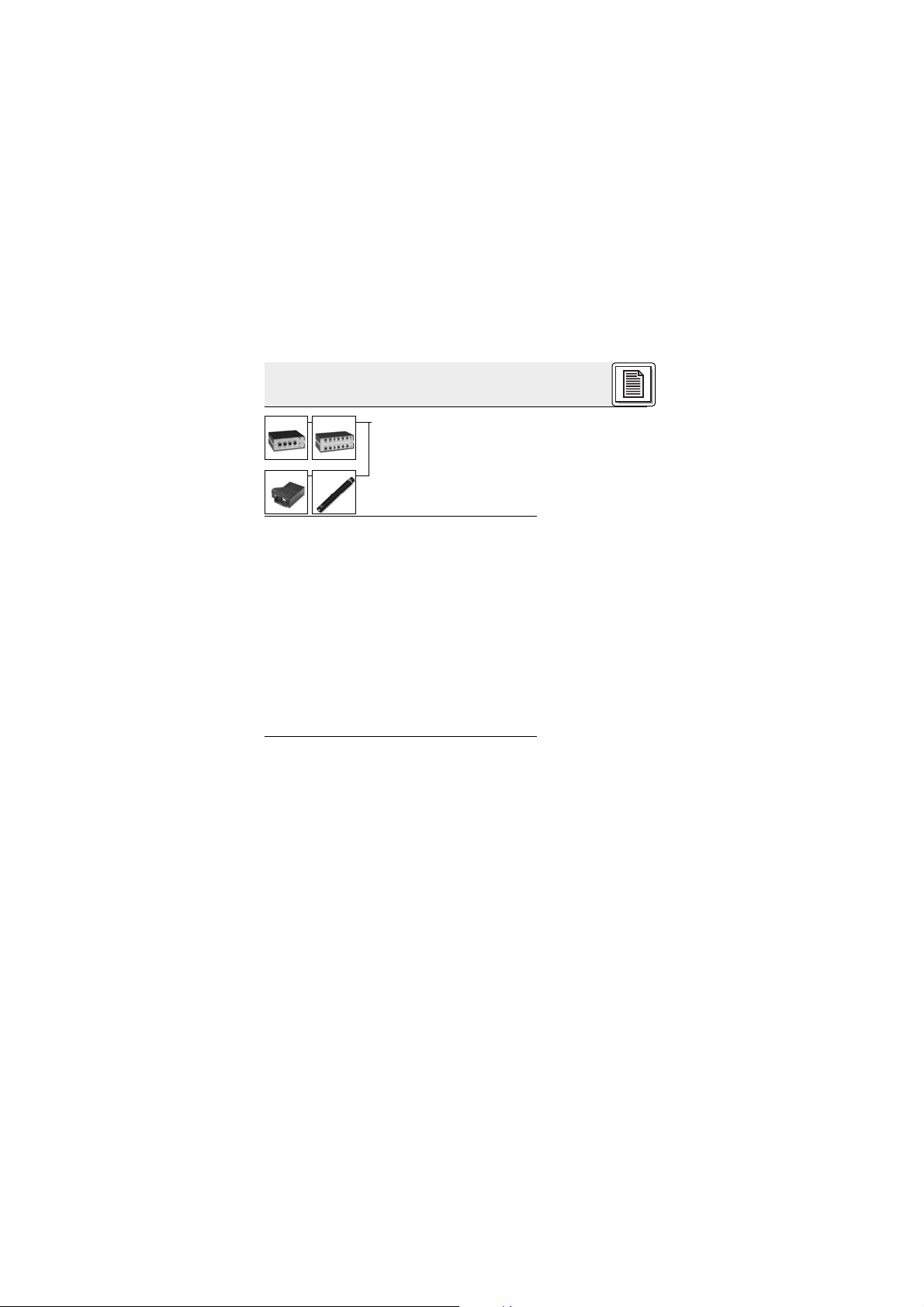
1 x C 416
III
1x H 416 1 x W 44
3 Stück Zylinderblechschrauben (2,9
x 13 mm),
3 Stück Flachkopfschrauben
(3 x 30 mm)
2 Stück doppelseitig klebebeschichtete
Gummiplättchen
Elastische
Klebemasse
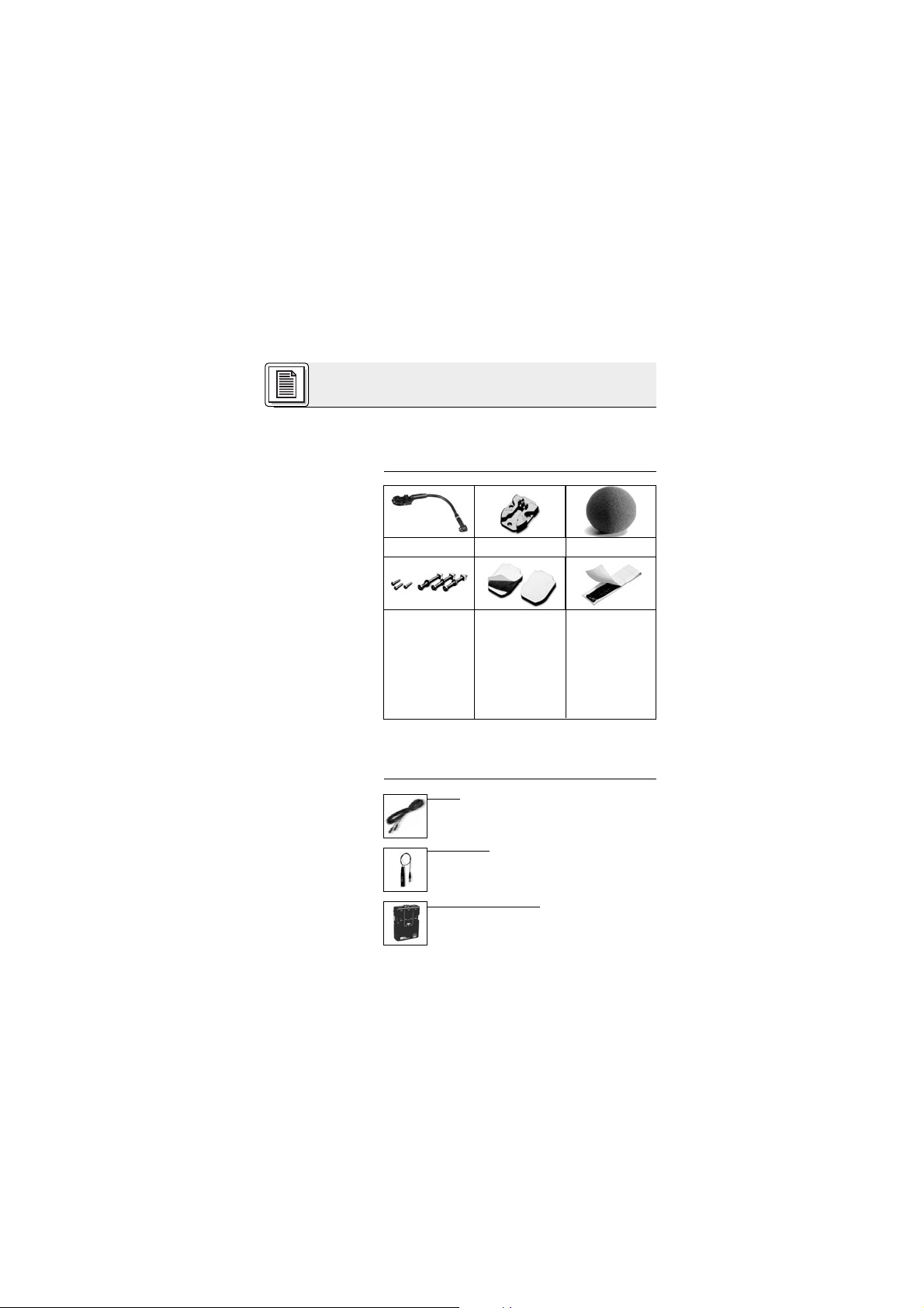
• Mikrofonkabel MK 9/10: 10 m 2-polig
geschirmtes Kabel mit XLR-Stecker
und XLR-Kupplung
• Phantomspeiseadapter
MPA III L (für C 416
III
L)
• Batteriespeisegerät
B 29 L (für C 416
III
L)
Page 3

3
1 Beschreibung
1.4 Besondere
Merkmale
1.5 Kurzbeschreibung
• Robustes Miniatur-Kondensatormikrofon für
Instrumentalabnahme auf der Bühne.
•Frequenzgang speziell für Akkordeon, Gitarren/Bassverstärker und Klavier ausgelegt.
•Hohe Rückkopplungssicherheit durch frequenzunabhängige hypernierenförmige Richtcharakteristik.
• 100 mm langer Schwanenhals zur exakten Positionierung des Mikrofons.
•Wirkungsvolle Unterdrückung mechanischer
Störgeräusche durch elastische Lagerung des
Schwanenhalses.
• Externer Windschutz und Zubehör für die direkte Montage am Instrument oder an der
Lautsprecherbox im Lieferumfang enthalten.
Das C 416
III
ist ein Kondensator-Miniaturmikrofon
mit hypernierenförmiger Richtcharakteristik. Es
wurde speziell für die direkte Montage an Akkordeons, Boxen von Gitarren- oder Bassverstärkern,
Pianinos und Flügeln entwickelt. Die mitgelieferten
Schrauben und Befestigungselemente erlauben
eine sichere Befestigung des Mikrofons am Instrument oder der Lautsprecherbox. Sie können entweder das Mikrofon selbst fix montieren oder nur
das mitgelieferte Montageplättchen H 416. Das Mikrofon rastet sicher im Montagepättchen ein, kann jedoch leicht wieder abgezogen werden. Ein 100 mm
langer Schwanenhals erlaubt Ihnen, das Mikrofon exakt für optimalen Sound zu positionieren.
• Phantomspeisegeräte
N 62 E, N 66 E,
B 18, B 15
(für C 416
III
PP)
Page 4
4
1 Beschreibung
1.6 Varianten
C 416
III
PP
C 416
III
L
2.1 Einleitung
Wichtig!
2.2 C 416
III
PP
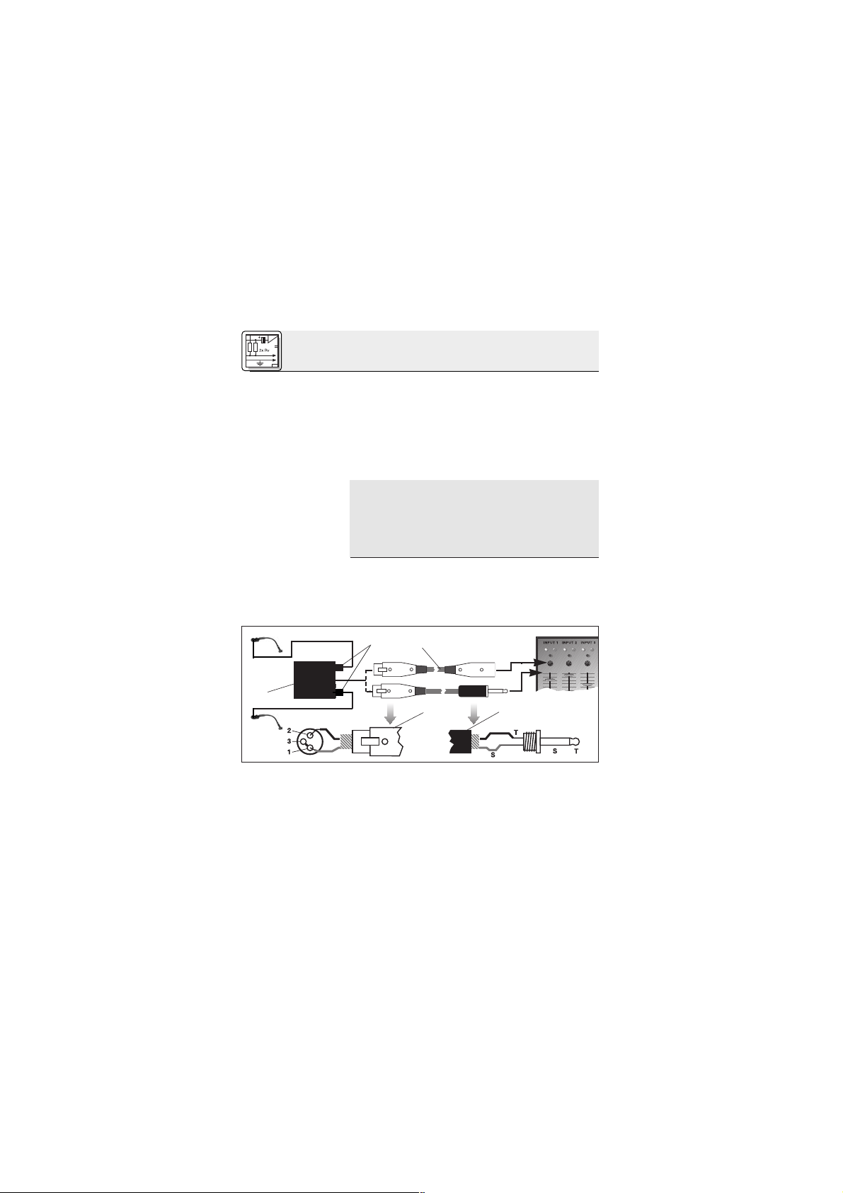
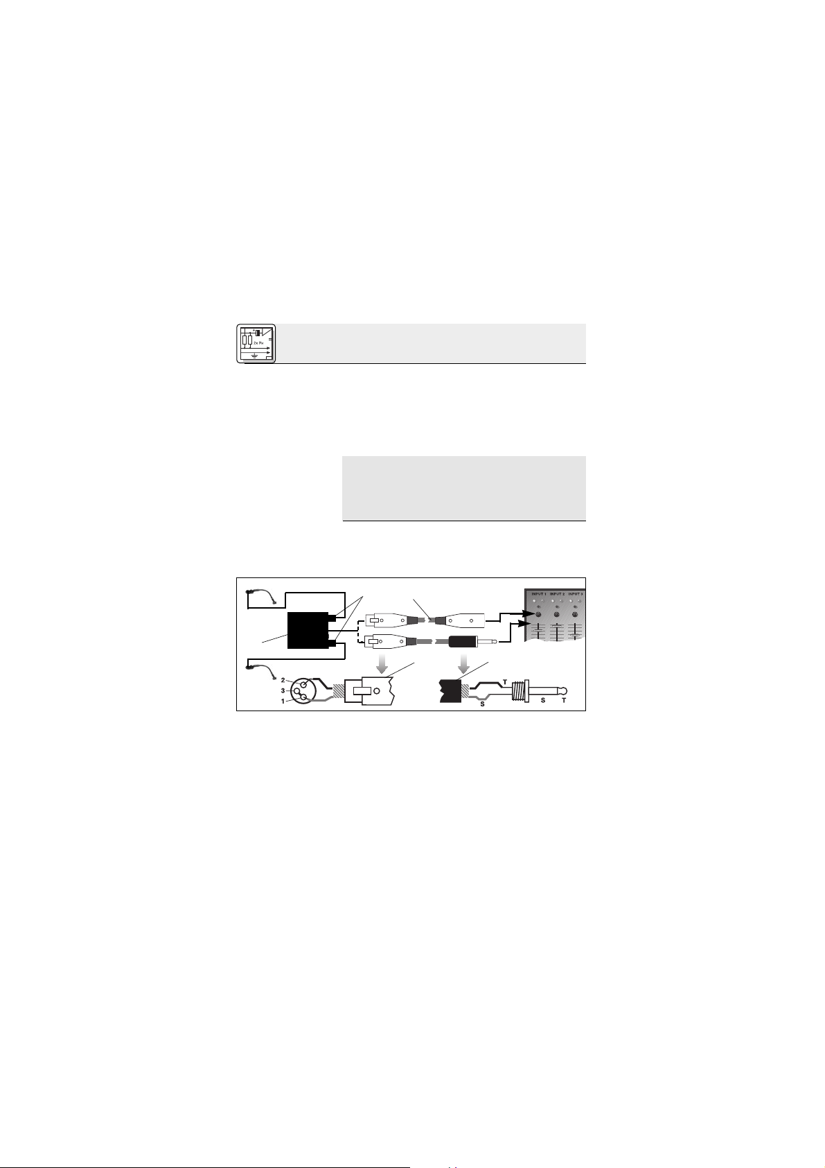
2.2.1 Anschluss
an symmetri-
sche Eingänge
Siehe Abb.1.
Der hochwertige Kondesatorwandler mit
frequenzunabhängiger hypernierenförmiger
Richtcharakteristik bietet eine natürliche, detailreiche Wiedergabe und ist sehr unempfindlich gegen akustische Rückkopplungen sowie Übersprechen von benachbarten Instrumenten.
Durch die elastische Lagerung des Schwanenhalses ist das Mikrofon weitgehend unempfindlich
gegen Körperschall vom Instrument oder der
Lautsprecherbox.
Das Mikrofon ist in zwei Ausführungen erhältlich:
• Für 9 bis 52 V Universal-Phantomspeisung.
3 m langes, fix verbundenes Anschlusskabel
mit Phantomspeiseadapter mit integriertem
3-poligem XLR-Stecker.
• Für Speisung mittels Batteriespeisegerät
B 29 L, Phantomspeiseadapter MPA III L oder
AKG.WIRELESS-Taschensender. 1,5 m langes, fix verbundenes Anschlusskabel mit
3-poligem Mini-XLR-Stecker.
Das C 416
III
PP/C 416
III
L ist ein Kondensatormi-
krofon und benötigt daher eine Stromversorgung.
Wenn Sie andere als die von AKG empfohlenen
Speisegeräte verwenden, kann das Mikrofon
beschädigt werden und erlischt die Garantie.
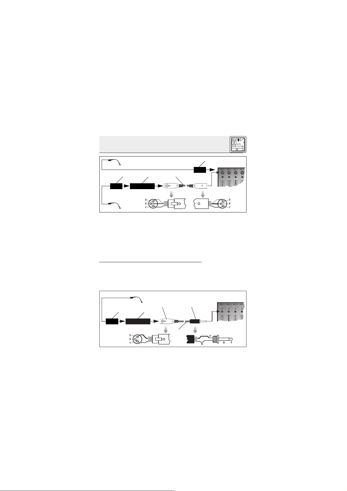
1. Stecken Sie den Phantomspeiseadapter (1) am
Mikrofonkabel an einen symmetrischen XLRMikrofoneingang mit Phantomspeisung an.
2. Schalten Sie die Phantomspeisung ein. (Lesen
Sie dazu in der Betriebsanleitung des jeweiligen Gerätes nach.)
2 Anschluss
Page 5
5
2 Anschluss
2.2.2 Anschluss
an asymmetrische Eingänge
Siehe Abb. 2.
3. Wenn Ihr Mischpult keine Phantomspei-
sung besitzt, stecken Sie den Phantomspeiseadapter (1) an ein optionales AKG-Phantomspeisegerät (2) (N 62 E, N 66 E, B 18, B 15) an
und verbinden Sie das Phantomspeisegerät (2)
mit Hilfe eines XLR-Kabels (3) (z.B. MK 9/10
von AKG - nicht mitgeliefert) mit einem symmetrischen Eingang.
Phantomspeisegeräte von AKG können Sie auch
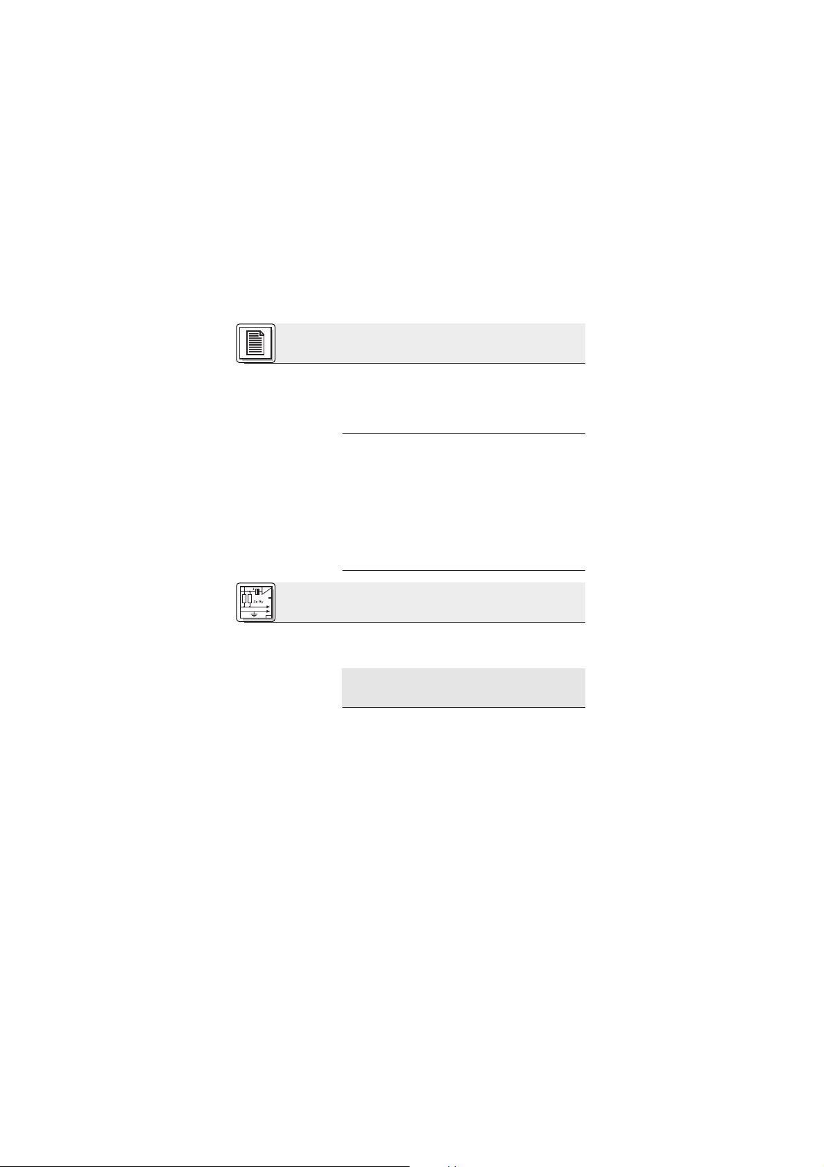
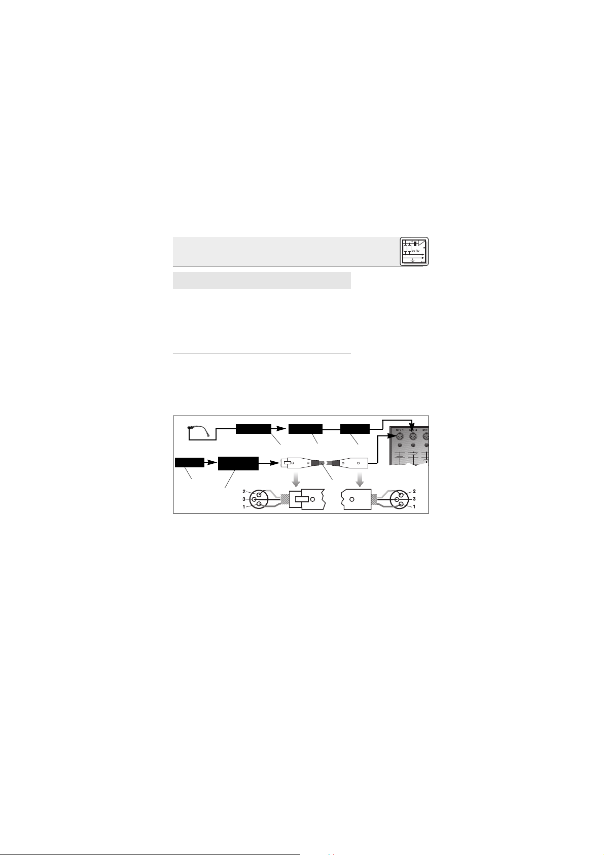
an einen asymmetrischen Eingang anschließen.
Verwenden Sie dazu ein Kabel mit XLR-Stecker
(weiblich) und Mono-Klinkenstecker:
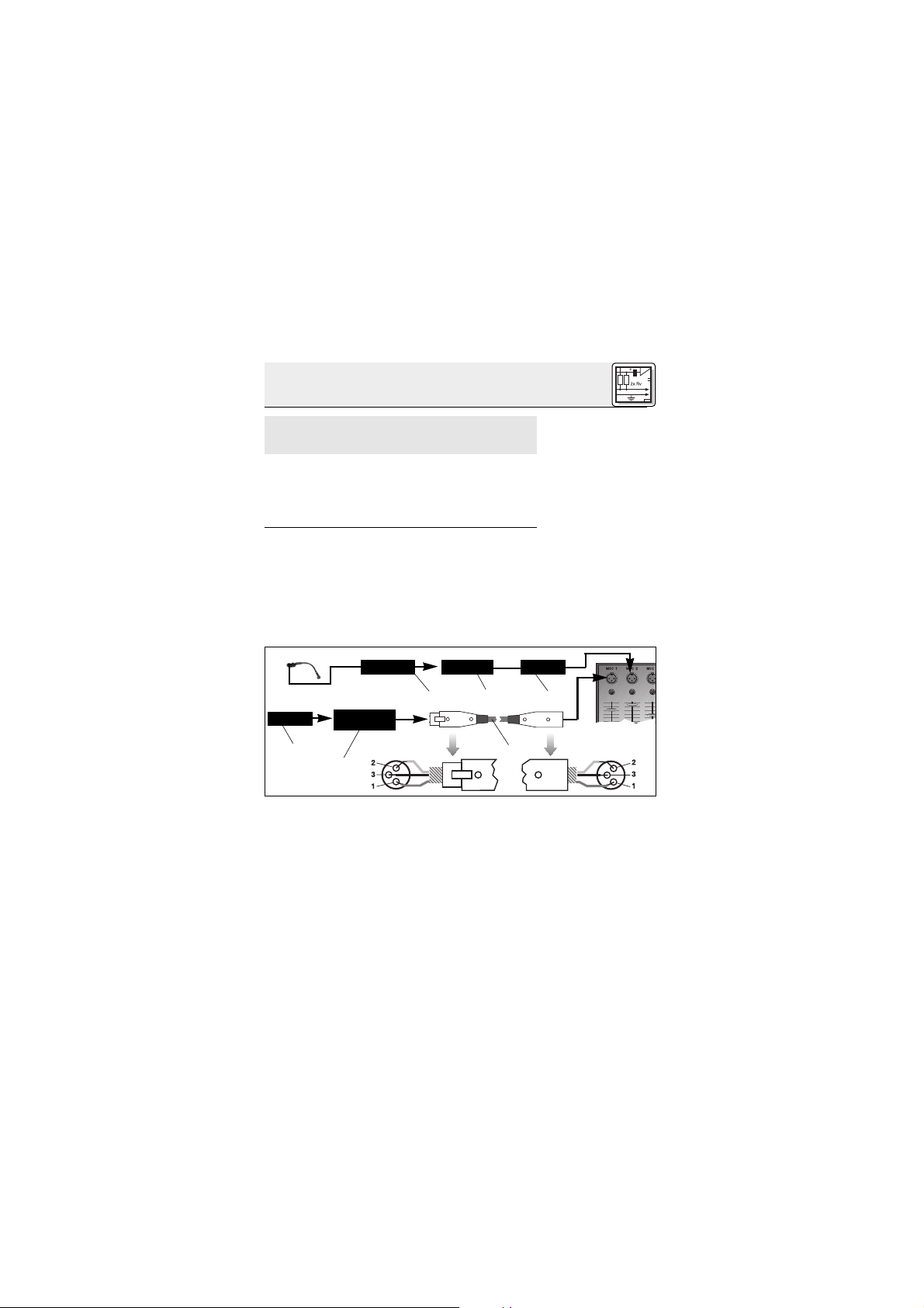
Abb. 1: Anschluss an symmetrischen Eingang
Phantom
MPA
MPA
Abb. 2: Anschluss an asymmetrischen Eingang
PhantomMPA
Page 6
6
2 Anschluss
Hinweis:
2.3 C 416
III
L
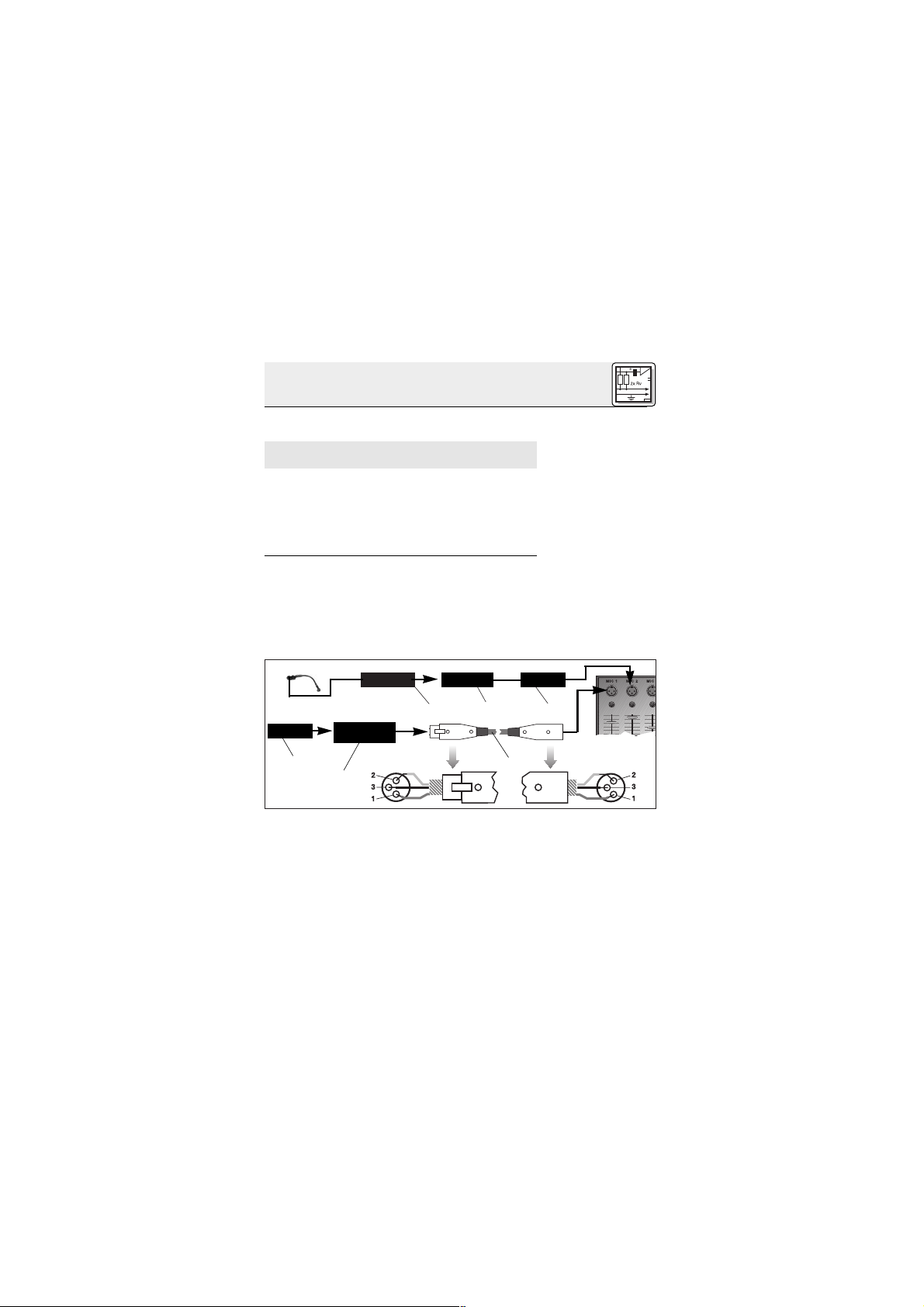
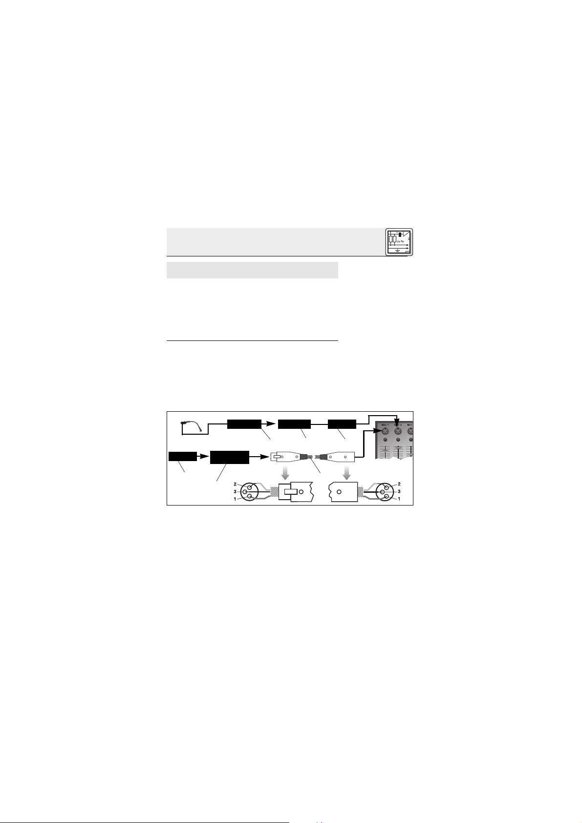
2.3.1 Anschluss
mittels B 29 L
Siehe Abb.3.
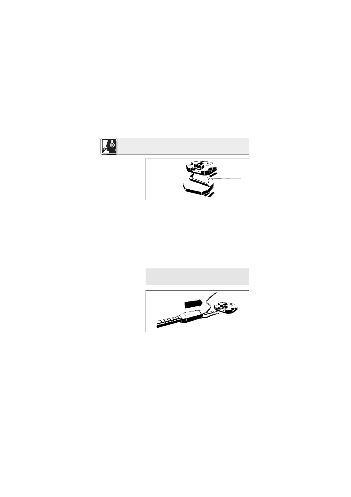
Kabel anstecken:
Kabel abziehen:
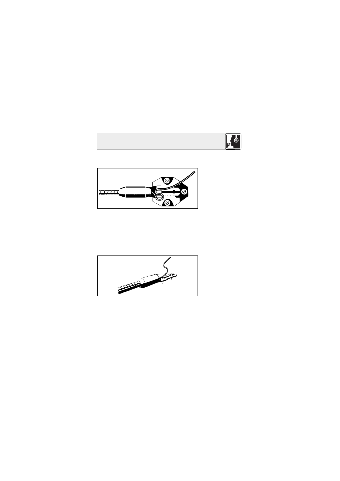
1. Verbinden Sie im XLR-Stecker (4) mittels einer
Drahtbrücke Stift 1 mit Stift 3 und mit der Abschirmung.
2. Verbinden Sie die innere Ader des Kabels mit
Stift 2 des XLR-Steckers (4) und der Spitze des
Klinkensteckers (5).
3. Verbinden Sie die Abschirmung des Kabels
mit dem Schaft des Klinkensteckers (5).
Beachten Sie, dass asymmetrische Kabel Einstreuungen aus Magnetfeldern (von Netz- und
Lichtkabeln, Elektromotoren usw.) wie eine Antenne aufnehmen können . Bei Kabeln, die länger
als 5 m sind, kann dies zu Brumm- und ähnlichen
Störgeräuschen führen.
Mit dem optionalen Batteriespeisegerät B 29 L
können Sie das Mikrofon an symmetrische oder
asymmetrische Eingänge ohne Phantomspeisung
anschliessen.
1. Stecken Sie den Mini-XLR-Stecker (1) am
Mikrofonkabel bis zum Anschlag in eine der
beiden Mini-XLR-Buchsen am B 29 L (2).
Der Stecker (1) verriegelt sich automatisch.
Zum Abziehen des Kabels drücken Sie auf
den Entriegelungsknopf am Mini XLR-Stecker
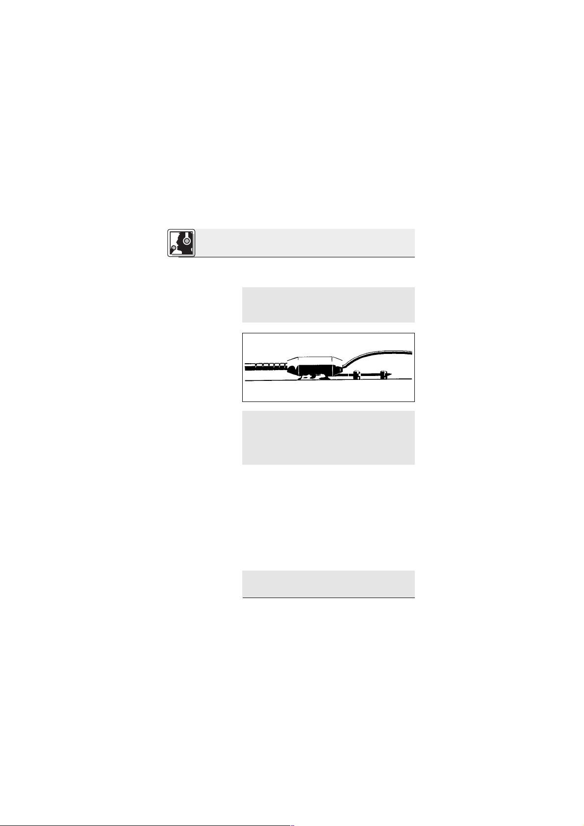
Abb. 3: Anschluss-Schema mit B 29 L
B 29 L
Page 7
7
2 Anschluss
Wichtig!
Siehe Abb. 3.
Symmetrischer
Eingang:
Asymmetrischer
Eingang:
2.3.2 Anschluss
mittels MPA III L
Kabel anstecken:
Siehe Abb. 4.
Kabel abziehen:
Siehe Abb. 4.
(1) und ziehen Sie den Stecker (1) aus der
Buchse heraus.
Um das Kabel nicht zu beschädigen, ziehen Sie niemals am Kabel selbst!
2. Verbinden Sie das B 29 L (2) mit dem
gewünschten Eingang.
• Zum Anschluss an einen symmetrischen
Eingang verwenden Sie ein handelsübliches XLR-Kabel (3).
• Siehe Kapitel 2.2.2.
1. Stecken Sie den Mini-XLR-Stecker (1) am
Mikrofonkabel bis zum Anschlag in die MiniXLR-Kupplung (2) am Anschlusskabel des
MPA III L (3).
Der Stecker (1) verriegelt sich automatisch.
Siehe Kapitel 2.3.1.
2. Stecken Sie den MPA III L (3) an einen symmetrischen XLR-Mikrofoneingang mit Phantomspeisung an.
3. Schalten Sie die Phantomspeisung ein. (Lesen
Sie dazu in der Betriebsanleitung des jeweiligen Gerätes nach.)
4. Wenn Ihr Mischpult keine Phantom-
speisung besitzt, stecken Sie den MPA III L
Mini XLR Mini XLR MPA
MPA
Phantom
Abb. 4: Anschluss-Schema mit MPA III L
Page 8
8
2 Anschluss
2.3.3 Anschluss an
Taschensender
3.1 Einleitung
3.2 Mikrofon
befestigen
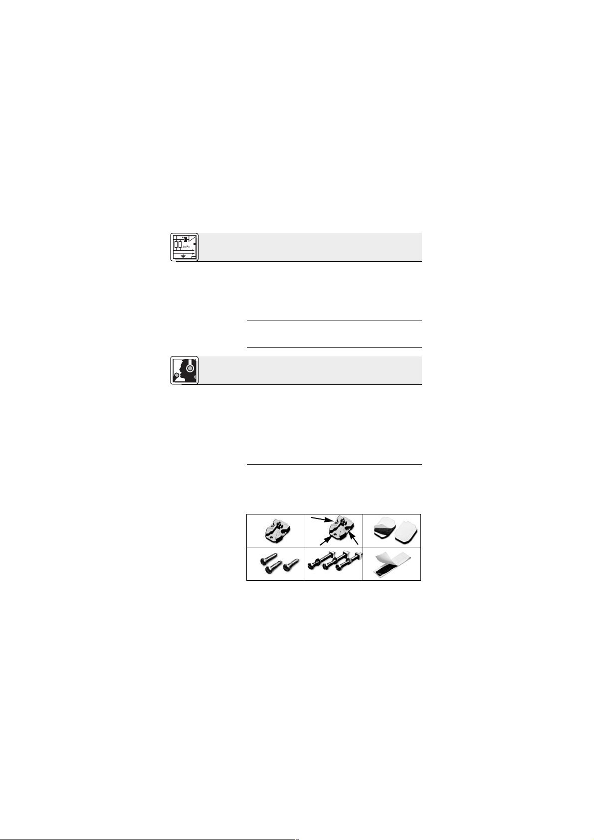
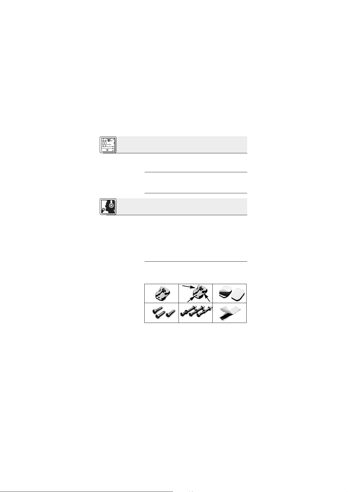
Abb. 5: Montage-
material
(3) an ein optionales AKG-Phantomspeisegerät (4) (N 62 E, N 66 E, B 18, B 15) an und
verbinden Sie das Phantomspeisegerät (4) mit
Hilfe eines XLR-Kabels (5) (z.B. AKG MK 9/10
- nicht mitgliefert) mit einem symmetrischen
Eingang.
Lesen Sie in der Bedienungsanleitung Ihres
Taschensenders nach.
Bevor Sie das Mikrofon endgültig am Instrument
oder der Lautsprecherbox befestigen, testen Sie
das Mikrofon an verschiedenen Stellen, um den
besten Sound zu finden. Befestigen Sie das Mikrofon dazu provisorisch mit der mitgelieferten
Klebemasse.
Bewährte Mikrofonpositionen und weitere Anwendungshinweise finden Sie in Kapitel 3.3 bis 3.5.
Sie können das Mikrofon entweder fix oder mittels
lösbarer Schnappverbindung am Instrument oder
der Lautsprecherbox montieren.
Dazu liegen dem Mikrofon folgende Teile bei:
1 Montageplättchen H 416
2 3 Gummitüllen (in H 416 eingesetzt)
3 Anwendung
1 2 3
564
Page 9
9
3 Anwendung
3.2.1 Montage
mittels H 416
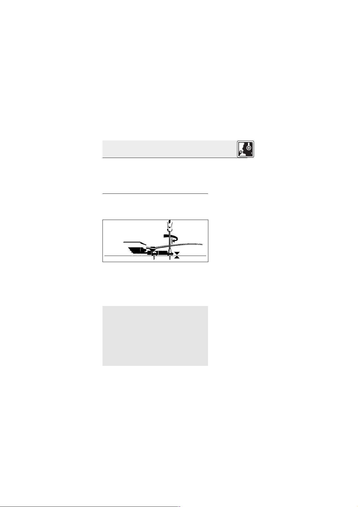
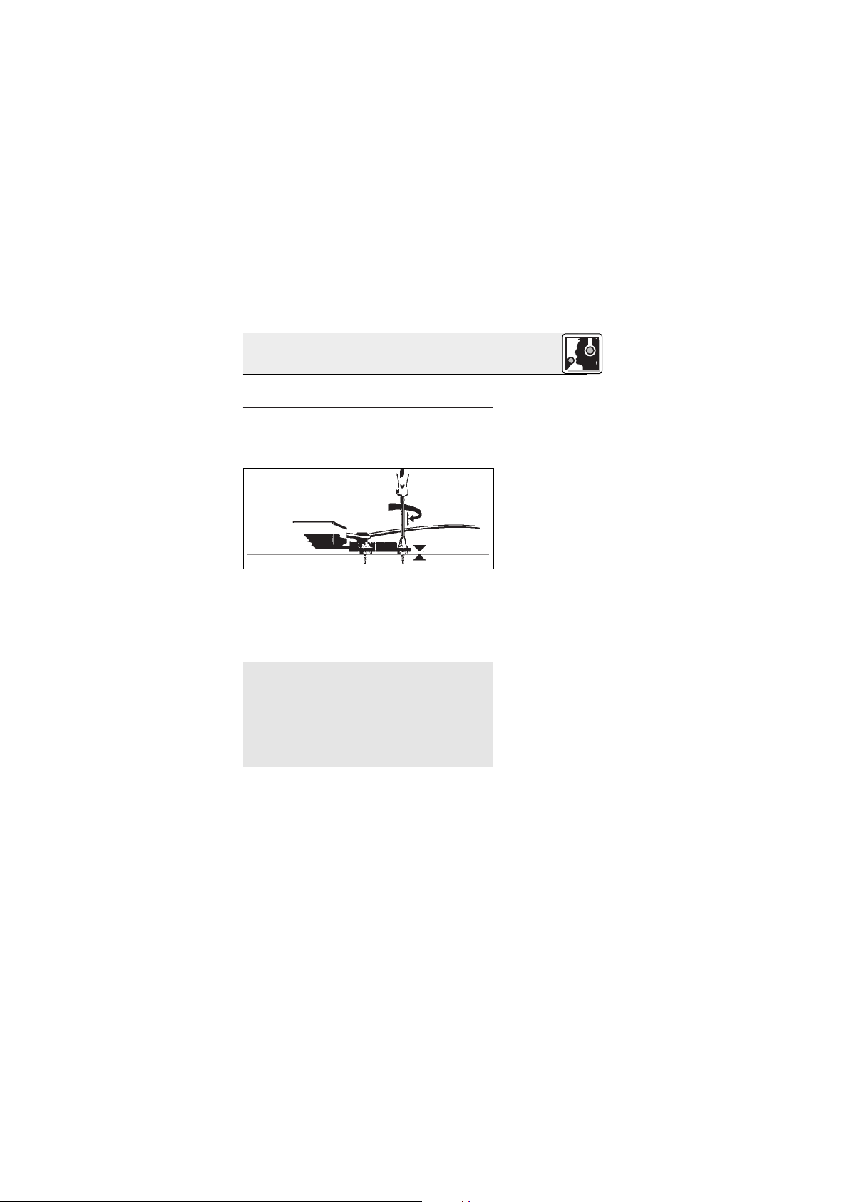
Abb. 6: H 416 anschrauben
Siehe Abb. 6.
Wichtig!
3 2 Stk. doppelseitig klebebeschichtete Gummi-
plättchen
4 3 Zylinderblechschrauben, 2,9 x 13 mm
5 3 Flachkopfschrauben mit Kontermutter,
3 x 30 mm
6 Klebemasse
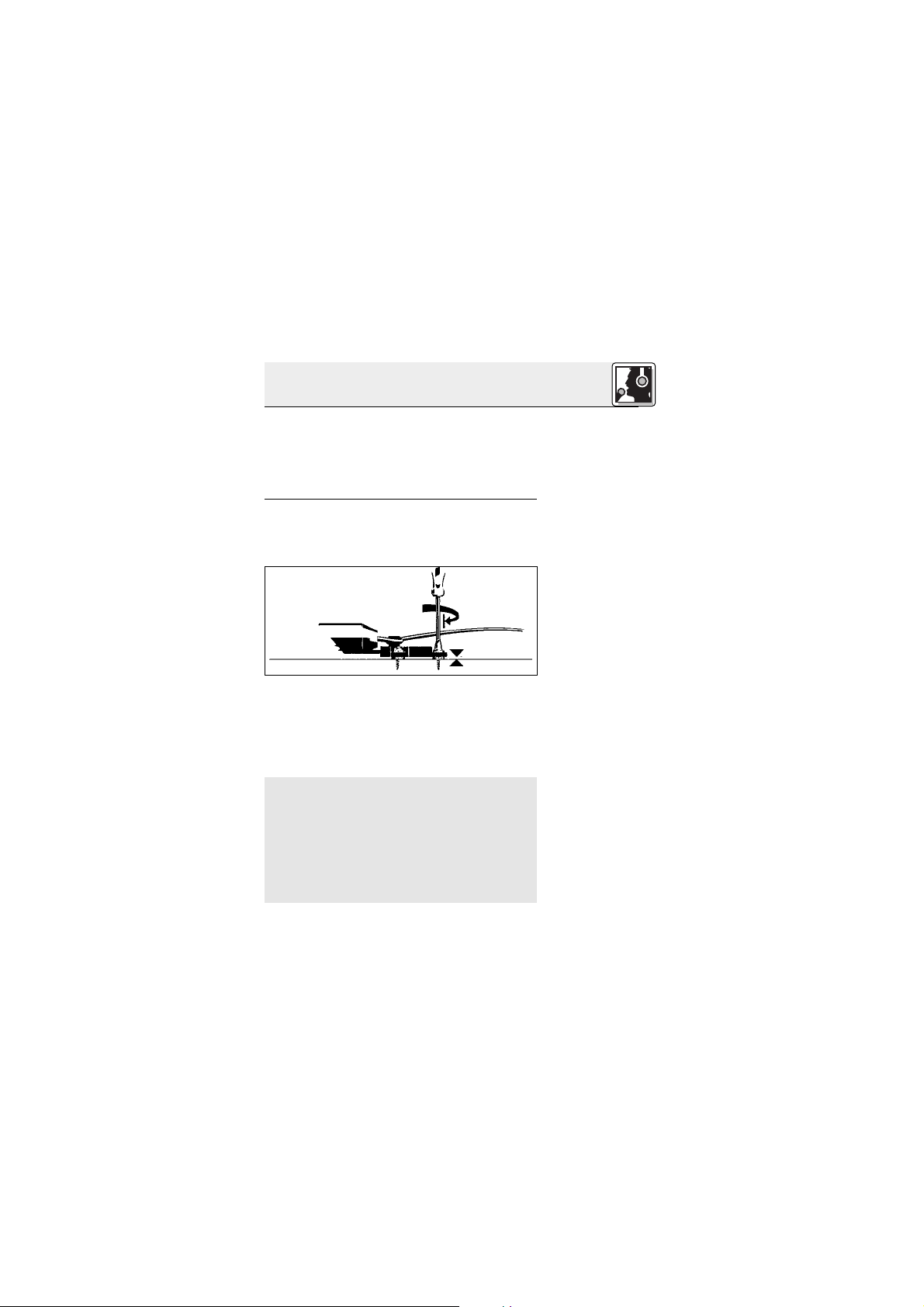
1. Befestigen Sie das Montageplättchen H 416
am Instrument oder der Lautsprecherbox. Sie
haben dazu folgende Möglichkeiten:
a) Befestigung mittels Schrauben:
•Verwenden Sie, je nach Wandstärke und Material des Gehäuses, die mitgelieferten 13 mm
langen Zylinderblechschrauben oder die 30
mm langen Flachkopfschrauben mit Kontermutter.
Achten Sie darauf, die Schrauben nur soweit anzuziehen, dass die Gummitüllen
nicht zusammengedrückt werden.
Die Gummitüllen wirken als elastische Lagerung des Mikrofons und unterdrücken zusammen mit dem im Mikrofonarm integrierten Elastomer-Dämpfungselement wirksam die Übertragung störender Körperschallgeräusche.
Werden die Gummitüllen zusammengedrückt,
geht die Wirksamkeit dieser elastischen Lagerung verloren.
Page 10
10
3 Anwendung
Abb. 7: doppel-
seitig klebendes
Gummiplättchen
Siehe Abb. 7.
Hinweis:
Abb. 8: Mikrofon in
das H 416
einschieben
Siehe Abb. 8.
b) Befestigung ohne Schrauben an ebenen
Flächen:
• Ziehen Sie das Abdeckpapier von beiden Seiten des Gummiplättchens ab und drücken Sie
das Gummiplättchen fest an das H 416 und an
das Instrument oder die Lautsprecherbox.
c) Befestigung ohne Schrauben an unebenen
Flächen:
•Verwenden Sie anstelle des Gummiplättchens
die mitgelieferte Klebemasse.
Die Körperschallkompensation ist in beiden
Fällen (b und c) gleich wie bei der Befestigung
mittels Schrauben.
2. Schieben Sie die Lasche am Schwanenhals in
das Montageplättchen H 416 ein, bis sie hörbar einrastet.
Sie können das Mikrofon jederzeit demontie-
Page 11
11
3 Anwendung
Abb. 9: Kabelzugentlastung
Siehe Abb. 9.
3.2.2 Fixe
Montage
Abb. 10: Mikrofon
direkt am Instrument/an der Box
anschrauben
Siehe Abb. 10.
ren, um es z.B. vor Schäden beim Transport zu
schützen.
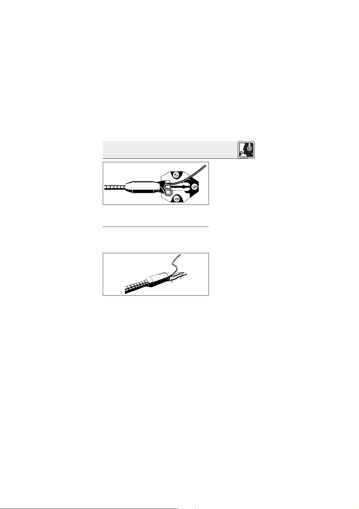
3. Legen Sie das Kabel um die Stege am Montageplättchen, um das Mikrofon vom Zug des
Kabels zu entlasten.
Zur fixen Befestigung des Mikrofons am Instrument oder an der Box haben Sie folgende Möglichkeiten:
A. Montage mittels Schrauben
1. Lösen Sie zwei Gummitüllen aus dem Montageplättchen H 416 und schieben Sie die Gummitüllen durch den Schlitz in der Lasche am
Schwanenhals in die beiden Bohrungen.
2. Verwenden Sie zum Befestigen des Mikrofons,
je nach Wandstärke und Material des Gehäuses, die mitgelieferten 13 mm langen Zylinder-
Page 12
12
3 Anwendung
Wichtig!
Abb. 11: Klebe-
masse als Schutz
gegen Scheppern
Hinweis:
Siehe Abb. 11.
Hinweis:
blechschrauben oder die 30 mm langen Flachkopfschrauben mit Kontermutter.
Um die körperschalldämpfende Wirkung
der Gummitüllen zu erhalten, ziehen Sie die
Schrauben nur soweit an, dass die Gummitüllen nicht zusammengedrückt werden.
Wenn Sie das Mikrofon an einer ebenen Fläche
montiert haben, drücken Sie die mitgelieferte
Klebemasse unter das Dämpungselement am
Schwanenhals. Die Klebemasse unterdrückt
Vibrationen des Schwanenhalses und das damit verbundene Scheppern.
B. Befestigung ohne Schrauben an ebenen
Flächen
• Ziehen Sie das Abdeckpapier von beiden Seiten des Gummiplättchens ab und drücken Sie
das Gummiplättchen fest an die Lasche und an
das Instrument oder die Lautsprecherbox.
C. Befestigung ohne Schrauben an unebenen
Flächen
•Verwenden Sie anstelle des Gummiplättchens
die mitgelieferte Klebemasse.
Die Körperschallkompensation ist in beiden
Fällen (B und C) gleich wie bei der Befestigung
mittels Schrauben.
Page 13
13
3 Anwendung
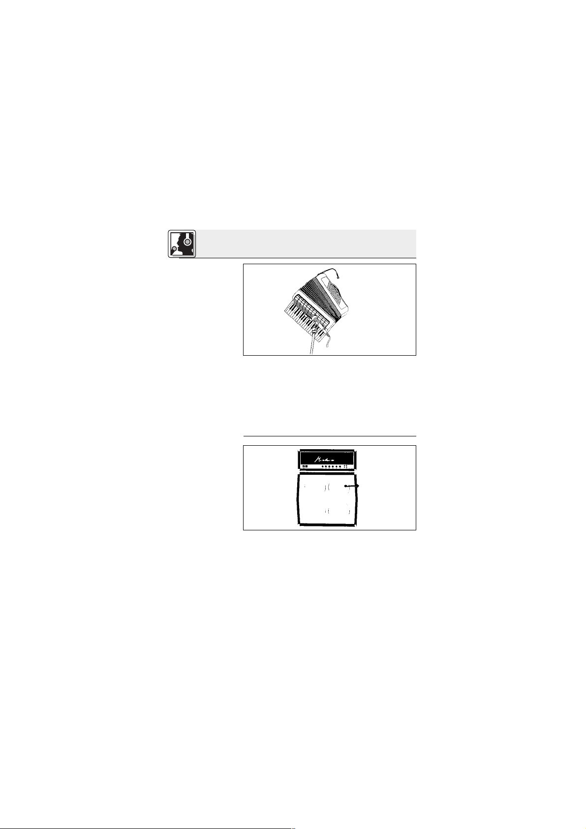
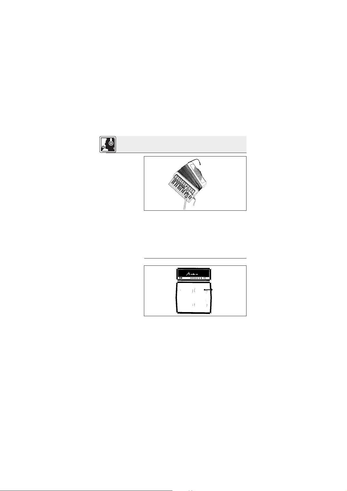
3.3 Akkordeon
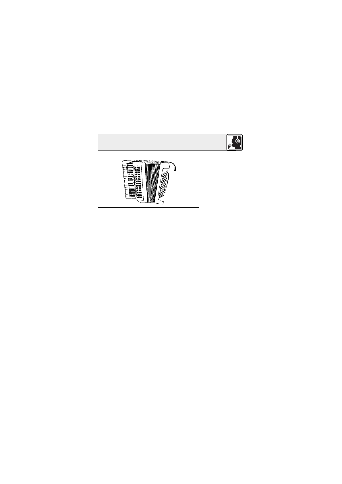
Abb. 12: Akkordeonabnahme mit
zwei C 416
III
Siehe Abb. 12.
Zur optimalen Abnahme des Akkordeons benötigen Sie zwei Mikrofone, eines für den Bassbereich
und eines für den Diskant. Mit dem Schwanenhals
können Sie das Mikrofon genau auf das Instrument ausrichten.
Bei größeren Instrumenten können Sie das Mikrofon auch unter der Verschalung des Akkordeons
einbauen. Wir empfehlen, in diesem Fall den mitgelieferten Windschutz W 44 zur Unterdrückung
von Blasgeräuschen des Blasebalgs auf das Mikrofon zu stecken.
Führen Sie die Kabel der beiden Mikrofone entlang eines der Trägerriemen am Rücken zusammen und von dort zum Batteriespeisegerät B 29 L,
den Taschensendern, zum Mischpult etc., damit
die Kabel beim Spielen nicht stören.
Page 14
14
3 Anwendung
Abb. 13: Akkordeonabnahme mit
C 416
III
und stativ-
gebundenem
Mikrofon
Siehe Abb. 13.
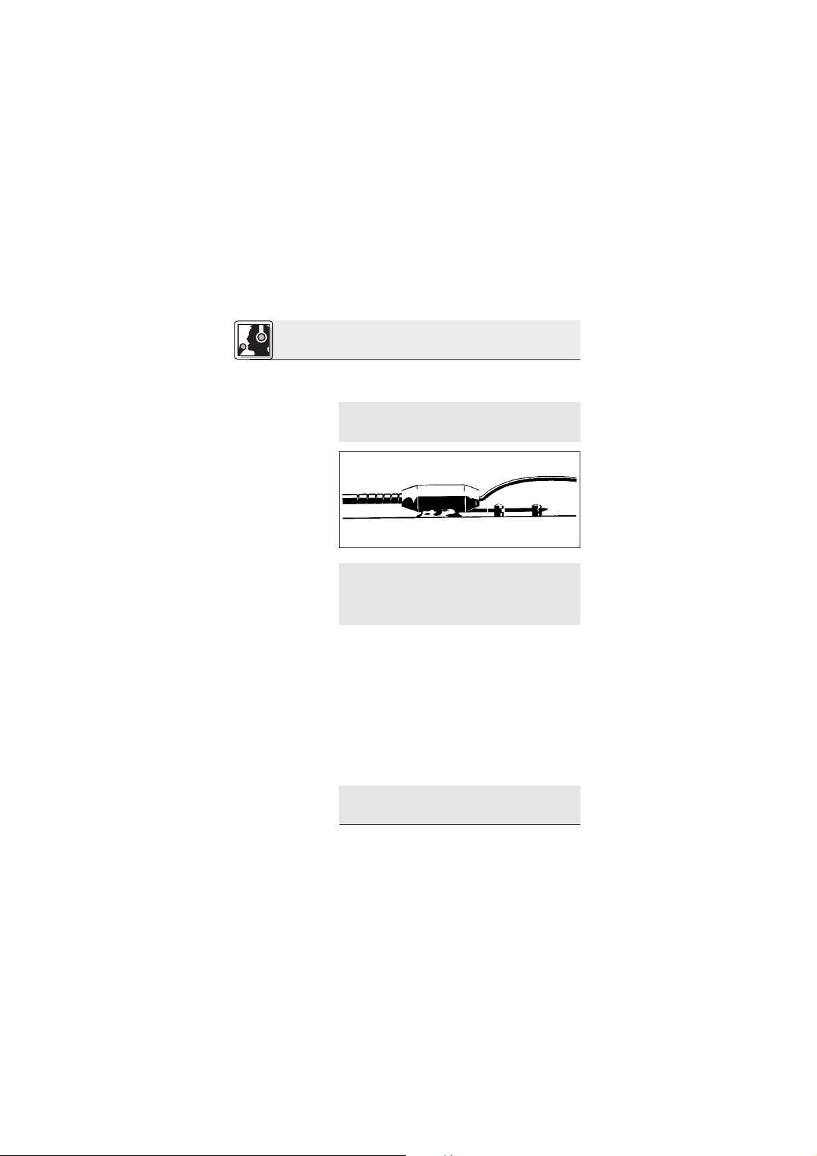
3.4 Gitarren-,
Bassverstärker-
box, Leslie
Abb. 14:
Gitarren/Bass-
verstärker
Siehe Abb. 14.
Sie können das Akkordeon auch mit einem
C 416
III
und einem stativgebundenen Mikrofon ab-
nehmen:
1. Befestigen Sie das C 416
III
auf der Bassseite
des Akkordeons und richten Sie das Mikrofon
auf eines der Schalllöcher aus.
2. Richten Sie das stativgebundene Mikrofon auf
die Diskantseite des Akkordeons aus.
Positionieren Sie das Mikrofon ausserhalb des
Zentrums eines Lautsprechers, um den Verstärkersound unverfälscht zu übertragen. Wenn Sie
das Mikrofon direkt auf das Zentrum des Lautsprechers ausrichten, kann der Sound zu scharf
werden.
Page 15
15
3 Anwendung
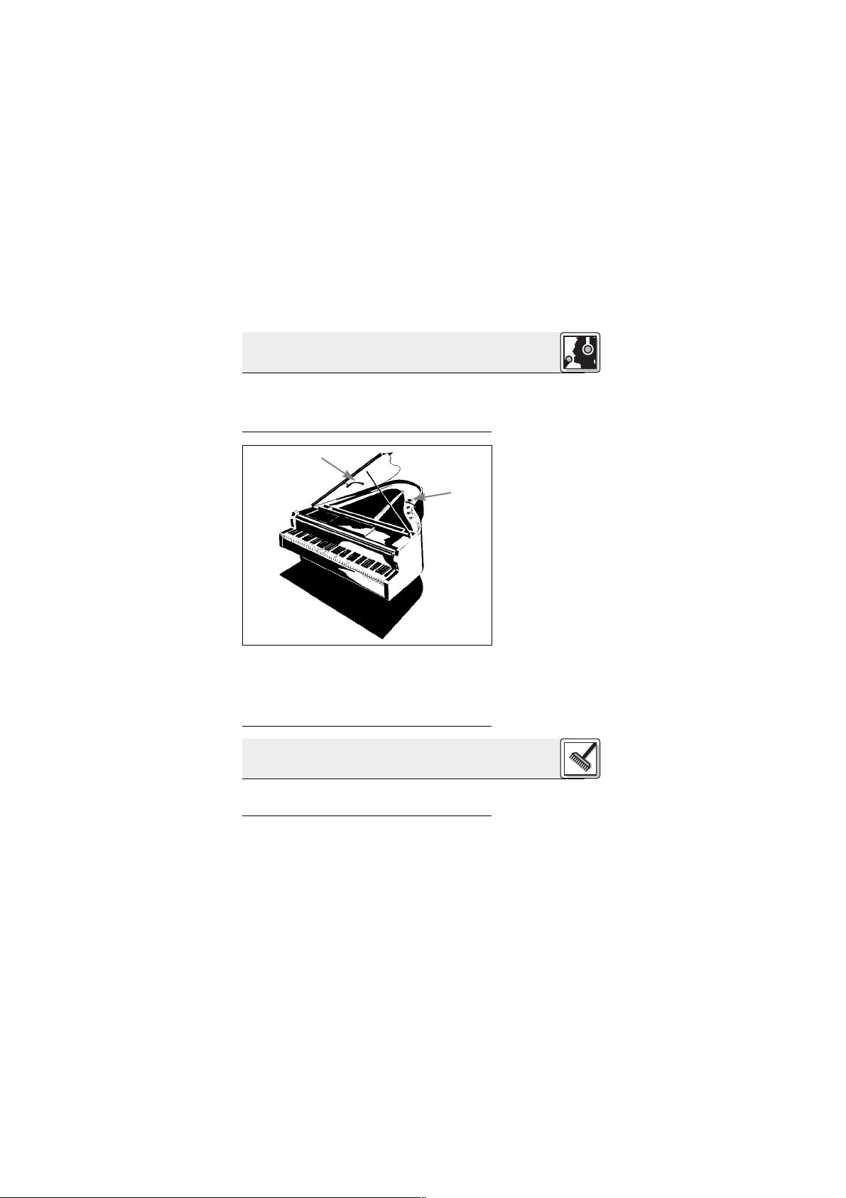
3.5 Flügel
Abb. 15: Abnahme
des Flügels mit
zwei C 416
III
Siehe Abb. 15.
Für die Abnahme von Mehrwegboxen und Leslies
empfehlen wir, zwei Mikrofone zu verwenden, eines für den Hoch- und Mitteltonlautsprecher und
eines für den Bassbereich.
Auf Grund der sehr großen Abstrahlfläche des
Klaviers empfehlen wir, zwei Mikrofone zu verwenden, um ein neutrales Klangbild zu erreichen.
Richten Sie ein Mikrofon auf den Bassbereich und
das zweite auf die mittleren und hohen Saiten aus.
Reinigen Sie das Gehäuse des Mikrofons mit einem mit Wasser befeuchteten Tuch.
4 Reinigung
Page 16

16
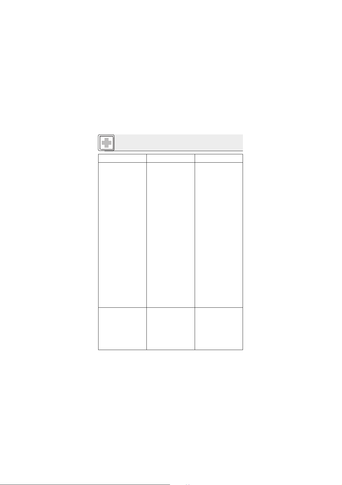
5 Fehlerbehebung
Fehler
Kein Ton:
Verzerrungen:
Mögliche Ursache
1. Mischpult und/oder
Verstärker ausgeschaltet.
2. Kanal-Fader oder
Summenpegelregler
am Mischpult oder
Lautstärkeregler des
Verstärkers steht auf
Null.
3. Mikrofon nicht an
Mischpult oder
Verstärker angeschlossen.
4. Kabelstecker nicht
richtig angesteckt.
5. Kabel defekt.
6. Keine Speisespannung.
1. Gain-Regler am
Mischpult zu weit
aufgedreht.
2. Mischpulteingang zu
empfindlich.
Abhilfe
1. Mischpult und/oder
Verstärker einschalten.
2. Kanal-Fader oder
Summenpegelregler
am Mischpult oder
Lautstärkeregler des
Verstärkers auf gewünschten Pegel
einstellen.
3. Mikrofon an Mischpult oder Verstärker
anschließen.
4. Kabelstecker
nochmals anstecken.
5. Kabel überprüfen
und falls nötig ersetzen.
6. Phantomspeisung
einschalten.
Phantomspeisegerät: ans Netz
anschließen bzw.
Batterie(n) einlegen.
Kabel überprüfen
und falls nötig ersetzen.
1. Gain-Regler zurückdrehen.
2. 10-dB-Vorabschwächung
zwischen Mikrofonkabel und Eingang
stecken.
Page 17
17
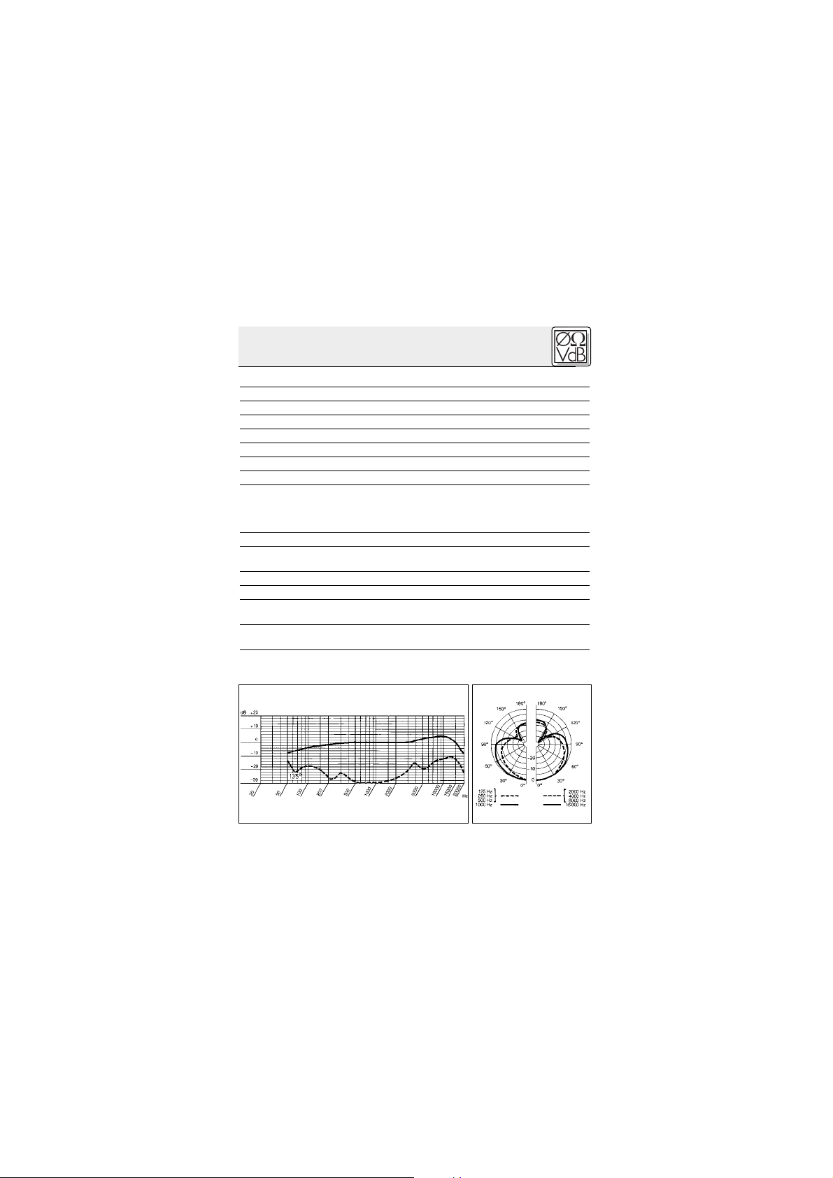
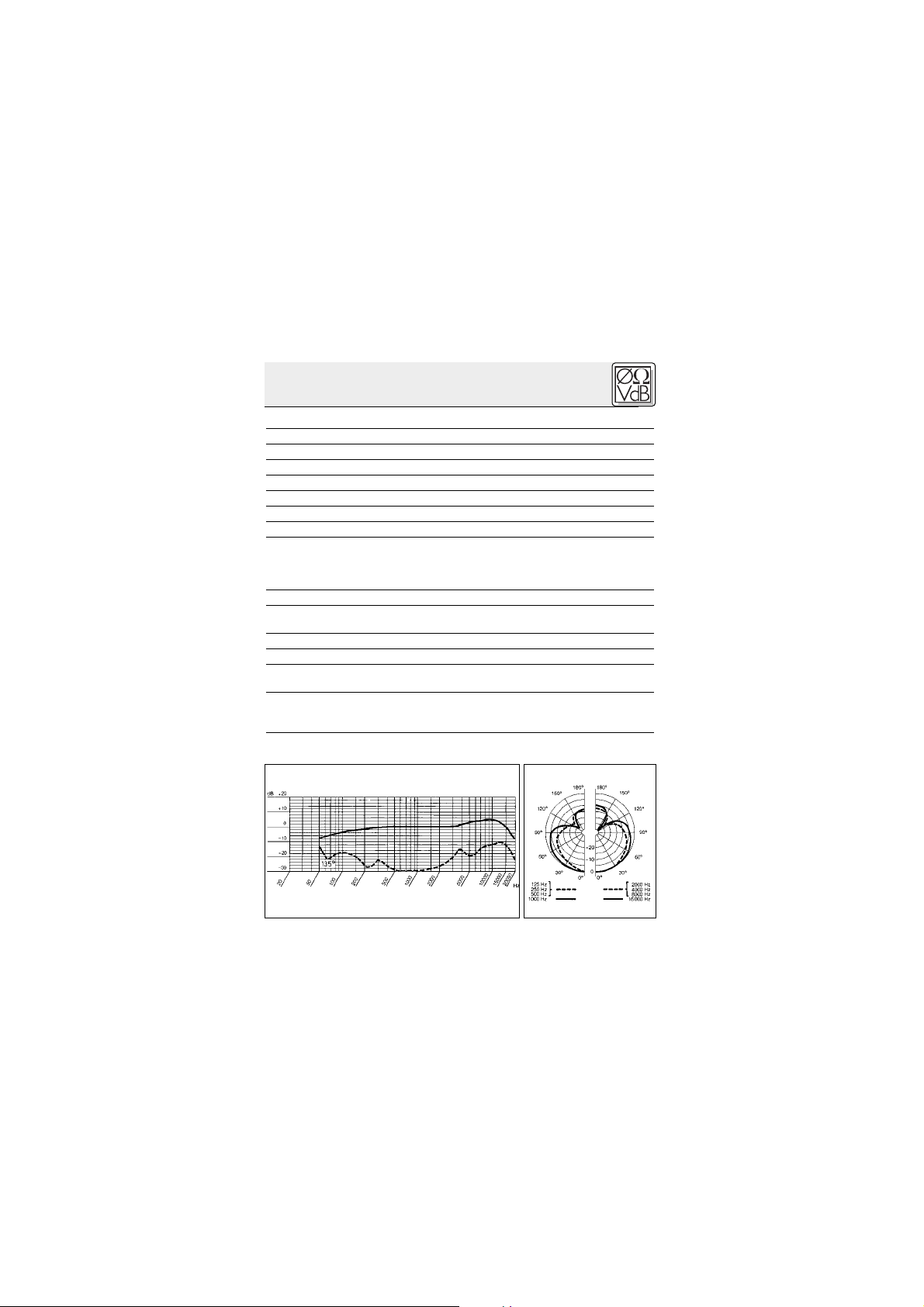
6 Technische Daten
Arbeitsweise: Kondensatorwandler mit Permanentladung
Richtcharakteristik: Hyperniere
Übertragungsbereich: 20 – 20.000 Hz
Empfindlichkeit: 7 mV/Pa = –43 dBV re 1 V/Pa
Elektrische Impedanz bei 1000 Hz: 200 Ω
Empfohlene Lastimpedanz: ≥2000 Ω
Grenzschalldruck für 1 %/3 % Klirrfaktor: 121 dB/131 dB
Äquivalentschalldruckpegel: 30 dB (DIN 45412)
Speisespannung: C 416
III
PP: 9–52 V Phantomspeisung
C 416
III
L: Batteriespeisegerät B 29 L,
Phantomspeiseadapter MPA III L, AKG
WMS Taschensender
Stromaufnahme: ca. 2 mA
Kabellänge/Steckerart: C 416
III
PP: 3 m / XLR 3-polig
C 416
III
L: 1,5 m / Mini-XLR 3-polig
Oberfläche: mattschwarz
Ahbmessungen: 235 x 30 mm
Netto/Bruttogewicht: C 416
III
PP: 120 g / 455 g
C 416
III
L: 55 g / 390 g
Dieses Produkt entspricht der Norm EN 500-82/1, vorausgesetzt, dass nachgeschaltete Geräte CE-konform sind.
Frequenzgang Polardiagramm
Page 18

18
1 Precaution/Description
1.1 Precaution
1.2 Unpacking
1.3 Optional
Accessories
Please make sure that the piece of equipment
your microphone will be connected to fulfills the
safety regulations in force in your country and is
fitted with a ground lead.
Check that the packaging contains all of the components listed above. Should anything be missing, please contact your AKG dealer.
1 x C 416
III
1x H 416 1 x W 44
3 x fillister head
self-tapping
screws (2.9 x
13 mm) , 3 x
pan-head bolts
and nuts (3 x
30mm)
2 x doublesided adhesive
rubber plates
Elastic adhesive putty
• MK 9/10 microphone cable: 10-m
(30-ft.) 2-conductor shielded cable
w/male and female XLR connectors
• MPA III L phantom power adapter
(for C 416
III
L)
• B 29 L battery power supply
(for C 416
III
L)
Page 19

19
1 Description
1.4 Features
1.5 Brief
Description
• Rugged condenser microphone for instrument
miking on stage.
•Frequency response tailored to accordeon,
guitar/bass amp, and piano miking.
•Frequency-independent hypercardioid polar
response for high gain before feedback.
• 100-mm (4-in.) gooseneck for accurate microphone alignment.
• Gooseneck shock mount reduces handling
and cable noise.
• Complete with external windscreen and accessories for mounting the micorphone on an
instrument or speaker.
The C 416
III
is a miniature hypercardioid condenser microphone. It has been specifically designed
for direct attachment to an accordion, guitar or
bass amp speakers, and upright or grand pianos.
The supplied screws and mounting hardware
allow you to fix the microphone securely on the instrument or speaker cabinet. You can permanently mount either the microphone itself or the
supplied H 416 installation plate. The microphone
snaps securely into the installation plate and can
be removed easily. A 4-inch (100-mm) gooseneck
lets you align the micorphone precisely for optimum sound.
The high quality condenser transducer with its frequency-independent hypercardioid polar pattern
provides a natural, detailed sound, high gain be-
• N 62 E, N 66 E, B 18, B15
phantom power suppplies
(for C 416
III
PP)
Page 20
20
1 Description
1.6 Versions
C 416
III
PP
C 416
III
L
2.1 Introduction
Important!
2.2 C 416
III
PP
2.2.1 Connecting
to Balanced
Inputs
Refer to fig. 1.
fore feedback, and good rejection of spillover from
nearby instruments.
The gooseneck uses a special shock mount that
makes the microphone highly insensitive to mechanical noise from the instrument or speaker.
The C 416
III
is available in two versions:
• For 9 to 52 V universal phantom power. 10-ft.
(3-m) permanently attached connecting cable
with phantom power adapter with integrated
3-pin XLR connector.
• For use with the B 29 L battery power supply,
MPA III L phantom power adapter, or
AKG.WIRELESS bodypack transmitters. 5-ft.
(1.5-m) permanently attached connecting cable with 3-pin mini XLR connector
The C 416
III
is a condenser microphone and there-
fore needs a power supply.
Using any power supply other than those
recommended by AKG may damage your
microphone and will void the warranty.
1. Connect the phantom power adapter (1) on the
microphone cable to a balanced XLR microphone input with phantom power.
2. Switch the phantom power on. (Refer to the instruction manual of the unit to which you
connected your microphone.)
2 Interfacing
Page 21

21
2 Interfacing
Refer to fig. 1.
2.2.2 Connecting
to Unbalanced
Inputs
Refer to fig. 2.
3. If your mixer provides no phantom power:
Connect the phantom power adapter (1) to an
optional AKG phantom power supply (2) (N 62 E,
N 66 E, B 18, B 15) and use an XLR cable (3)
(e.g., an optional MK 9/10 from AKG) to connect
the phantom power supply to the desired
balanced input.
You may connect any AKG phantom power supply (2) to an unbalanced input, too.
Use a cable (3) with a female XLR connector and
TS jack plug:
Fig. 1: Connecting to a balanced input.
Phantom
MPA
MPA
Fig. 2: Connecting to an unbalanced input.
PhantomMPA
Page 22
22
2 Interfacing
Note:
2.3 C 416
III
L
2.3.1 Using the
Optional B 29 L
Connecting the
cable:
Refer to fig. 3.
Disconnecting
the cable:
1. On the XLR connector (4), use a wire bridge to
connect pin 1 to pin 3 and the cable shield.
2. Connect the inside wire of the cable to pin 2
on the XLR connector (4) and the tip contact
of the jack plug (5).
3. Connect the shield of the cable to the shaft
contact on the jack plug (5).
Unbalanced cables may pick up interference
from stray magnetic fields near power or lighting
cables, electric motors, etc. like an antenna.
This may introduce hum or similar noise if you
use a cable that is longer than 16 feet (5 m).
The optional B 29 L battery supply allows you to
connect the microphone to balanced or unbalanced inputs with no phantom power.
1. Push the mini XLR connector (1) on the microphone cable into one of the two mini XLR
sockets on the B 29 L (2) to the stop.
The connector will lock automatically.
To disconnect the cable, press the unlocking
button on the mini XLR connector (1) and pull
the connector (1) out of the socket.
Fig. 3: Using the B 29 L to power the microphone.
B 29 L
Page 23
23
2 Interfacing
Important!
Refer to fig. 3.
Balanced input:
Unbalanced input:
2.3.2 Using the
MPA III L
Connecting the cable:
Refer to fig. 4.
Disconnecting
the cable:
Refer to fig. 4.
To avoid damaging the cable, never try to
pull out the cable itself!
2. Connect the B 29 L (2) to the desired input.
• Use a commercial XLR cable (3) to connect
the B 29 L (2) to a balanced input.
• Refer to section 2.2.2 above.
1. Push the mini XLR connector (1) on the microphone cable into the mini XLR socket (2) on the
cable of the MPA III L (3) to the stop.
The connector will lock automatically.
Refer to section 2.3.1 above.
2. Connect the MPA III L (3) to a balanced XLR
microphone input with phantom power.
3. Switch the phantom power on. (Refer to the instruction manual of the unit to which you
connected your microphone.)
4. If your mixer provides no phantom power:
Connect the MPA III L (3) to an optional AKG
phantom power supply (4) (N 62 E, N 66 E, B 18,
Mini XLR Mini XLR MPA
MPA
Phantom
Fig. 4: Connection diagram with MPA III L.
Page 24
24
2 Interfacing
2.3.3 Connecting
to a Bodypack
Transmitter
3.1 Introduction
3.2 Mounting
the Microphone
Fig. 5: Mounting
hardware
B 15) and use an XLR cable (5) (e.g., an optional
MK 9/10 from AKG) to connect the phantom
power supply (4) to the desired balanced input.
Refer to the manual of your bodypack transmitter.
Before permanently mounting the microphone on
your instrument or speaker cabinet, experiment
with various microphone positions to get the best
possible sound. Fix the microphone temporarily
using the supplied adhesive putty.
Sections 3.3 to 3.5 describe proven techniques
that you may want to use as starting points for
your own experiments.
The supplied mounting hardware (see list below)
lets you mount the microphone either permanently or by a detachable snap-on connection.
1 H 416 installation plate
2 3 rubber eyelets (in H 416)
3 2 double-sided adhesive rubber plates
4 3 fillister head self-tapping screws
(2.9 x 13 mm)
3 Using Your Microphone
1 2 3
564
Page 25
25
3 Using Your Microphone
3.2.1 Snap-on
Mounting
Fig. 6: Screwing
down the H 416.
Refer to fig. 6.
Important!
5 3 pan-head bolts and nuts (3 x 30mm)
6 Elastic adhesive putty
1. Fix the H 416 installation plate on your instrument or speaker cabinet in one of the following
ways:
a) Using screws:
• Depending on the material and thickness of the
installation surface, use the 13-mm (0.5-in.) fillister head self-tapping screws or the 30-mm
(1.2-in.) pan-head bolts and nuts.
Be sure to tighten the screws without squeezing the rubber eyelets.
The rubber eyelets provide a shock mount for the
microphone. These eyelets together with the
elastomer damper incorporated in the gooseneck
effectively suppress the transmission of mechanical noise. Squeezing the rubber eyelets would destroy their effectiveness as shock mounts.
Page 26

26
3 Using Your Microphone
Fig. 7: Double-
sided adhesive
rubber plate.
Refer to fig. 7.
Note:
Fig. 8: Sliding the
microphone into
the H 416.
Refer to fig. 8.
b) Mounting the H 416 on a flat surface without
using screws:
• Remove the backing paper from both sides of
the rubber plate and press the rubber plate
firmly on the H 416 and then on the instrument
or speaker.
c) Mounting the H 416 on an uneven surface
without using screws:
• Use the supplied adhesive putty instead of the
rubber plate.
Both the rubber plate and the elastic putty provide the same amount of mechanical-noise attenuation as the rubber eyelets on the H 416.
2. Slide the bracket on the gooseneck into the
H 416 installation plate to the point that the
bracket audibly clicks into place.
You can remove the microphone easily, for in-
Page 27

27
3 Using Your Microphone
Fig. 9: Cable strain
relief.
Refer to fig. 9.
3.2.2 Permanent
Installation
Fig. 10: Fixing the
microphone directly on an instrument/speaker.
Refer to fig. 10.
stance, in order to prevent it being damaged
during shipping.
3. Place the cable around the fins on the installation plate to relieve the microphone of the
strain of the cable.
You can permanently mount the microphone on
your instrument or speaker cabinet in one of the
following ways:
A. Using Screws
1. Remove two of the rubber eyelets from the
H 416 installation plate and insert them into the
holes in the bracket, sliding them through the
slot.
2. Depending on the material and thickness of the
installation surface, use the 13-mm (0.5-in.) fillister head self-tapping screws or the 30-mm
Page 28
28
3 Using Your Microphone
Note:
Fig. 11: Adhesive
putty inserted to
prevent rattling.
Note:
Refer to fig. 11.
Note:
(1.2-in.) pan-head bolts and nuts to fix the
microphone.
To maintain the mechanical-noise attenuation
of the rubber eyelets, do not tighten the screws
hard enough to squeeze the eyelets.
If you mounted the microphone on a flat surface, insert some elastic adhesive putty between the surface and the gooseneck boss.
The adhesive putty will suppress gooseneck
vibrations and the resulting rattling noise.
B. Mounting the microphone on a flat surface
without using screws:
• Remove the backing paper from both sides of
the rubber plate and press the rubber plate
firmly on the bracket and then on the instrument or speaker.
C. Mounting the microphone on an uneven surface without using screws:
• Use the supplied adhesive putty instead of the
rubber plate.
Both the rubber plate and the elastic putty provide the same amount of mechanical noise attenuation as the rubber eyelets on the H 416.
Page 29

29
3 Using Your Microphone
3.3 Acordion
Fig. 12: Miking up
an accordion with
two C 416
III
s.
Refer to fig. 12.
To mic up an accordion optimally, you will need
two microphones, one for the bass and one for the
treble range. The gooseneck lets you align the
microphone exactly as desired.
If your instrument is big enough, you can even install the C 416
III
inside the case, making sure to
slip on the supplied W 44 windscreen to suppress
the wind noise produced by the bellows.
To keep the microphone cables out of your way,
join them and route them along one of the straps
and from there to a B 29 L, two bodypack transmitters, to the mixer, etc.
Page 30
30
3 Using Your Microphone
Fig. 13: Miking up
an accordion with
a C 416
III
and a
stand-mounted
microphone.
Refer to fig. 13.
3.4 Guitar/Bass
Amp Speaker,
Leslie Cabinet
Fig. 14:
Guitar/bass amp.
Refer to fig. 14.
Alternatively, you can mic up the accordion with
one C 416
III
and a stand-mounted microphone:
1. Mount the C 416III on the bass side of the accordion and point the microphone to one of the
sound holes.
2. Align the stand-mounted microphone with the
treble side of the accordion.
Place the microphone a little off the center of one
of the speakers in order to accurately capture the
sound of the amp. Pointing the microphone
directly at the center of the speaker may produce
an exceedingly harsh sound.
Page 31

31
3 Using Your Microphone
3.5 Grand Piano
Fig. 15: Miking up
a grand piano with
two C 416
III
s
Refer to fig. 15.
To mic up two- or three-way speakers and Leslie
cabinets, use two microphones, one for the high
and midrange driver and one for the bass driver.
The piano being a very large sound source, you
should use two microphones in order to get a neutral sound.
Aim one at the bass and one at the treble strings.
To clean the microphone case, use a soft cloth
moistened with water.
4 Cleaning
Page 32

32
5 Troubleshooting
Problem
No sound:
Distortion:
Possible Cause
1. Power to mixer
and/or amplifier is
off.
2. Channel or master
fader on mixer, or
volume control on
amplifier is at zero.
3. Microphone is not
connected to mixer or amplifier.
4. Cable connectors
are seated loosely.
5. Cable is defective.
6. No supply voltage.
1. Gain control on
the mixer set too
high.
2. Mixer input sensitivity too high.
Remedy
1. Switch power to
mixer or amplifier
on.
2. Set channel or
master fader on
mixer or volume
control on amplifier to desired
level.
3. Connect microphone to mixer or
amplifier.
4. Check cable
connectors for secure seat.
5.
Check cable and replace if damaged.
6. Switch phantom
power on.
Phantom power
supply: connect to
power outlet or insert battery
(batteries).
Check cable and replace if necessary.
1. Turn gain control
down CCW.
2. Connect a 10-dB
preattenuation
pad between
microphone cable
and input.
Page 33
33
6 Specifications
Type: pre-polarized condenser microphone
Polar pattern: hypercardioid
Frequency range: 20 Hz to 20,000 Hz
Sensitivity at 1 kHz: 7 mV/Pa (-43 dBV re 1 V/Pa)
Impedance: 200 Ω
Recommended load impedance: ≥2000 Ω
Max. SPL for 1%/3% THD: 121/131 dB SPL
Equivalent noise level: 30 dB (A) (to DIN 45412)
Power requirement:
C 416
III
PP: 9 to 52 V universal phantom power
C 416
III
L: B 29 L battery power supply,
MPA III L phantom adapter,
AKG WMS bodypack transmitters
Current consumption: approx. 2 mA
Cable length/Connector: C 416
III
PP: 3 m (10 ft.) / 3-pin male XLR
C 416
III
L: 1.5 m (5 ft.) / 3-pin mini XLR
Finish: matte black
Size: 235 x 30 mm (9.3 x 1.2 in.)
Net/shipping weight: C 416
III
PP: 120 g (4.2 oz.) / 455 g (15.9 oz.)
C 416
III
L: 55 g (1.9 oz.) / 390 g (13.6 oz.)
This product conforms to EN 50 082-1 provided it is connected to
equipment with a CE mark.
Frequency Response Polar Diagram
Page 34
34
1 Consigne de sécurité / Description
1.1 Consigne de
sécurité
1.2 Fournitures
1.3 Accessoires
optionnels
Vérifiez si l’appareil auquel vous voulez raccorder
le microphone répond aux prescriptions relatives
à la sécurité en vigueur et s’il possède une mise à
la terre de sécurité.
Contrôlez si le carton contient bien tous les éléments énumérés ci-dessus. Si ce n’est pas le cas,
veuillez contacter votre distributeur AKG.
1 x C 416
III
1x H 416 1 x W 44
3 vis à tête cylindrique (2,9 x
13 mm),
3 vis à tête
conique
(3 x 30 mm)
2 plaquettes de
caoutchouc
autocollantes
sur les deux
faces
mastic
élastique
•
Câble de micro MK 9/10 : câble blindé
bipolaire de 10 m, avec connecteurs
XLR mâle et femelle
• Adaptateur pour alimentation
fantôme MPA III L (pour C 416
III
L)
• Alimentations à piles
B 29 L (pour C 416
III
L)
Page 35
35
1 Description
1.4
Caractéristiques
particulières
1.5 Description
succincte
• Microphone électrostatique miniature robuste
pour la prise d’instruments sur scène.
• Réponse en fréquence spécialement adaptée
pour l’accordéon, les amplificateurs de guitare
et de basse et le piano.
• Remarquable immunité au larsen grâce à sa directivité hypercardioïde indépendante de la
fréquence.
• Col-de-cygne de 100 mm permettant de positionner le micro avec une grande précision.
• Suppression efficace des bruits mécaniques
grâce à la suspension élastique du col-de-cygne.
• La bonnette anti-vent externe et les accessoires pour le montage direct sur l’instrument ou
sur une enceinte sont fournis avec le micro.
Le C 416
III
est un microphone électrostatique miniature à directivité hypercardioïde. Il a été conçu spécialement pour le montage direct sur l’accordéon,
les enceintes d’amplis de guitare ou de basse, le piano droit ou le piano à queue. Les vis et éléments de
fixation fournis permettent de fixer solidement le
micro sur l’instrument ou l’enceinte. Vous pouvez
soit monter le micro à demeure, soit ne fixer sur l’instrument que la plaquette de montage H 416 fournie.
Le micro s’enclenche dans la plaquette qui le maintient en toute sécurité ; mais on peut aussi le détacher
facilement quand on le souhaite. Un col-de-cygne
de 100 mm permet de positionner le microphone
avec précision pour obtenir un son optimal.
•
Appareils d’alimentation fantôme
N 62 E, N 66 E, B 18, B 15
(pour C 416
III
PP)
Page 36

36
1 Description
1.6 Versions
C 416
III
PP
C 416
III
L
2.1 Introduction
Important!
2.2 C 416
III
PP
2.2.1
Raccordement
sur une entrée
symétrique
Voir fig. 1.
Le transducteur électrostatique de haute qualité, à
directivité cardioïde indépendante de la fréquence,
offre une restitution du son naturelle, ciselée ; il est
très peu sensible aux effets larsen de même qu’à la
diaphonie par rapport aux instruments voisins.
Grâce au montage élastique du col-de-cygne, le micro
est pratiquement insensible aux bruits de structure provenant d’un instrument ou d’une enceinte.
Le microphone existe en deux versions différentes:
• Pour alimentation fantôme universelle de 9 à
52 V. Câble de raccordement fixe de 3 m de long
avec module d’alimentation fantôme comportant un connecteur XLR 3 points intégré.
• Pour alimentation par boîtier à pile B 29 L, module d’alimentation fantôme MPA III L ou émetteur de poche AKG.WIRELESS. Câble de raccordement fixe de 1,5 m de long, avec connecteur mini-XLR 3 points.
Le C 416
III
PP/C 416
III
L est un microphone élec-
trostatique ; il a donc besoin d’une alimentation.
L’utilisation d’alimentations autres que celles recommandées par AKG peut provoquer
des dégâts sur le micro et entraîne la perte
de la garantie.
1. Connectez l’adaptateur pour alimentation
fantôme (1) du câble micro sur une entrée de
micro symétrique type XLR avec alimentation
fantôme.
2. Mettez l’alimentation fantôme sous tension
(Veuillez vous reporter à la notice de l’alimentation utilisée).
2 Raccordement
Page 37

37
2 Raccordement
Voir Fig. 1.
2.2.2
Raccordement
sur une entrée
asymétrique
3. Si vous n’avez pas d’alimentation
fantôme sur votre table de mixage, bran-
chez l’adaptateur pour alimentation fantôme
(1) sur une alimentation fantôme AKG optionnelle (2) (N 62 E, N 66 E, B 18, B 15) et raccordez l’alimentation fantôme à une entrée
symétrique à l’aide d’un câble XLR (3) (p.ex.
AKG MK 9/10 – n’est pas fourni avec le micro).
Vous pouvez aussi connecter les alimentations fantôme
d’AKG (2) sur une entrée asymétrique.
Il vous faut un câble (3) avec une fiche XLR femelle
et une fiche à jack mono:
Fig. 1 : Raccordement sur une entrée symétrique
Phantom
MPA
MPA
Fig. 2 : Raccordement sur une entrée asymétrique
PhantomMPA
Page 38

38
2 Raccordement
Voir Fig. 2.
N.B.
2.3 C 416
III
L
2.3.1
Raccordement
au moyen du
B 29 L
Brancher le câble:
Voir Fig. 3.
Débrancher le
câble :
1. Pontez les contacts 1 et 3 de la fiche XLR (4) et
reliez-les au blindage du câble.
2. Reliez le conducteur interne du câble au
contact 2 de la fiche XLR (4) et à la pointe de la
fiche à jack (5).
3.
Reliez le blindage du câble à la tige de la fiche à jack.
Les câbles asymétriques peuvent capter
comme une antenne les interférences de
champs magnétiques (câbles lumière ou force,
moteurs électriques, etc.). Si le câble mesure
plus de 5 m ce phénomène pourra se traduire
par des ronflements et autres parasites.
L’alimentation à pile B 29 L optionnelle vous permet de raccorder le micro à des entrées symétriques ou asymétriques sans alimentation fantôme.
1. Enfoncez le connecteur mini-XLR (1) du câble
du micro à fond dans une des deux embases
mini-XLR du B 29 L (2).
Le connecteur (1) se verrouille automatiquement.
Pour détacher le câble, appuyez sur le bouton
de déverrouillage du connecteur mini-XLR (1)
et sortez le connecteur de la prise.
Fig. 3 : Schéma de raccordement avec B 29 L
B 29 L
Page 39
39
2 Raccordement
Important !
Cf. Fig. 3.
Entrée symétrique:
Entrée asymétrique:
2.3.2
Raccordement
avec MPA III L
Brancher le câble:
Voir Fig. 4.
Débrancher le
câble :
Voir Fig. 4.
Pour ne pas risquer d’abîmer le câble, ne
sortez jamais le connecteur en tirant sur
le câble.
2. Raccordez le B 29 L (2) sur l’entrée voulue.
• Pour le raccordement sur une entrée symétrique, utilisez un câble XLR (3) en vente
dans le commerce.
•Voir point 2.2.2.
1. Enfoncez le connecteur mini-XLR (1) du câble
micro jusqu’en butée dans l’accouplement
mini-XLR (2) du câble de raccordement du
MPA III L (3).
Le connecteur (1) se verrouille automatiquement.
Voir point 2.3.1.
2. Connectez l’MPA III L (3) sur une entrée de
micro symétrique type XLR avec alimentation
fantôme.
3. Mettez l’alimentation fantôme sous tension
(Veuillez vous reporter à la notice de l’alimentation utilisée).
4. Si vous n’avez pas d’alimentation
fantôme sur votre table de mixage, branchez l’MPA III L (3) sur une alimentation
Mini XLR Mini XLR MPA
MPA
Phantom
Fig. 4: Schéma de raccordement avec MPA III L
Page 40

40
2 Raccordement
2.3.3
Raccordement
sur un émetteur
de poche
3.1 Introduction
3.2 Fixation du
microphone
Fig. 5 : Matériel de
montage
fantôme AKG optionnelle (4) (N 62 E, N 66 E,
B 18, B 15) et raccordez l’alimentation fantôme
à une entrée symétrique à l’aide d’un câble
XLR (5) (p.ex. AKG MK 9/10 – n’est pas fourni
avec le micro).
Conformez-vous aux instructions du mode d’emploi de votre émetteur de poche.
Avant de fixer le microphone définitivement sur un
instrument ou une enceinte, faites des essais en
changeant le micro de place pour trouver la position donnant le meilleur son. Pour ce faire, fixez
provisoirement le micro avec le mastic fourni.
Pour les positions donnant normalement les meilleurs résultats, veuillez vous reporter aux points
3.3 à 3.5 où vous trouverez également des conseils relatifs à l’utilisation.
Vous pouvez soit fixer le micro à demeure sur l’instrument ou l’enceinte, soit le monter à l’aide de
l’assemblage à encliquetage. A cet effet, les éléments suivants sont livrés avec le micro :
1 Plaquette de montage H 416
2
3 gaines de caoutchouc (se trouvant dans le H 416)
3 Utilisation
1 2 3
564
Page 41
41
3 Utilisation
3.2.1 Montage à
l’aide de la
plaquette H 416
Fig. 6 : Comment
visser la plaquette
H 416
Important !
3 2 plaquette de caoutchouc à deux faces auto-
collantes
4 3 vis à tête cylindrique, de 2,19 x 13 mm
5 3 vis à tête plate avec contre-écrou,
de 3 x 30 mm
6 Mastic
1. Fixez la plaquette de montage H 416 sur l’instrument ou sur l’enceinte. Il y a pour cela deux
méthodes :
a) Fixation par vis :
• Suivant l’épaisseur de la paroi et le matériau,
utilisez les vis à tôle à tête cylindrique de 13
mm de long ou les vis à tête plate avec contreécrou de 30 mm de long fournies.
Attention à ne pas comprimer les gaines de
caoutchouc en serrant les vis !
Les gaines de caoutchouc assurent le montage élastique du micro. Elles s’associent à
l’élément amortisseur en élastomère intégré au
bras de microphone pour neutraliser efficacement les bruits de structure. La compression
des gaines de caoutchouc rend le montage
élastique inefficace.
Page 42

42
3 Utilisation
Fig. 7 : Plaquette
de caoutchouc à
deux faces auto-
collantes
Voir Fig. 7
Remarque :
Fig. 8 : Introduire le
micro dans la
plaquette H 416
Voir Fig. 8
b) sans vis sur une surface plane :
• Enlevez le papier recouvrant les deux faces de
la plaquette de caoutchouc et collez celle-ci
sur la plaquette H 416 et sur l’instrument ou
l’enceinte, en appuyant fermement.
c) Fixation sans vis sur une surface non plane :
• Utilisez le mastic fourni au lieu de la plaquette
de caoutchouc.
La compensation des bruits de structure est
dans les deux cas (b et c) la même que dans le
cas d’une fixation par vis.
2. Introduisez la bride du col-de-cygne dans la
plaquette de montage H 416 et poussez à
fond; l’enclenchement est audible.
Vous pouvez démonter le micro quand vous le
souhaitez, p.ex. pour éviter qu’il ne s’abîme
pendant le transport.
Page 43
43
3 Utilisation
Fig. 9 : Suppression de la traction
sur le câble du
micro
Voir Fig. 9.
3.2.2 Montage fixe
Fig. 10 : Visser le
micro directement
sur l’instrument ou
l’enceinte
Voir Fig. 10.
3. Insérez le câble entre les moulures de la plaquette de montage pour supprimer la traction
sur le câble.
Pour fixer le micro directement sur l’instrument ou
l’enceinte, vous avez le choix entre différentes
méthodes :
A. Montage à l’aide de vis
1. Prélevez deux gaines de caoutchouc sur la
plaquette de montage H 416 et passez-les
dans les fentes de la bride du col-de-cygne
pour les introduire dans les deux trous.
2. Pour fixer le micro, utilisez, selon l’épaisseur
de la paroi et le matériau, les vis à tôle à tête
cylindrique de 13 mm de long ou les vis à tête
plate avec contre-écrou de 30 mm de long
fournies.
Page 44

44
3 Utilisation
Important !
Fig. 11 : Utilisation
du mastic contre
les vibrations
Remarque :
Voir Fig. 11.
Remarque :
Pour que les gaines de caoutchouc conservent leur effet d’amortissement des bruits
de structure, veillez à serrer les vis juste ce
qu’il faut, sans comprimer les gaines.
Lorsque vous avez monté le micro sur une surface plane, introduisez le mastic fourni sous
l’élément amortisseur du col-de-cygne. Le mastic absorbe les vibrations du col-de-cygne et
les bruits qui en résultent.
B. Fixation sans vis sur une surface plane
• Enlevez le papier recouvrant les deux faces de
la plaquette de caoutchouc et collez celle-ci
sur la bride et sur l’instrument ou l’enceinte, en
pressant fortement.
C. Fixation sans vis sur une surface non plane
• Utilisez le mastic fourni, à la place de la plaquette de caoutchouc.
La compensation des bruits de structure est
dans les deux cas (B et C) la même que dans le
cas d’une fixation par vis.
Page 45

45
3 Utilisation
3.3 Accordéon
Fig. 12 : Prise de
l’accordéon avec
deux C 416
III
Voir Fig. 12.
Pour une prise de son optimale sur l’accordéon,
on a besoin de deux micros: un pour le registre
des basses et un pour celui des aigus. Le col-decygne permet d’orienter le micro avec précision
par rapport à l’instrument.
Sur les gros accordéons, on peut aussi monter le
C 416
III
sous la coque; dans ce cas il est recommandé d’utiliser la bonnette antivent W 44 pour
atténuer les bruits de souffle provenant du soufflet.
Passez les câbles des micros le long de la bandoulière et faites-les partir du dos du musicien
vers l’alimenation à piles B 29 L, les émetteurs de
poche, le pupitre de mixage, etc., de manière à ne
pas gêner l’accordéoniste.
Page 46

46
3 Utilisation
Fig. 13 : Prise de
l’accordéon avec
le C 416
III
et un
micro sur pied
Voir Fig. 13.
3.4 Enceintes de
guitare et de
basse, Leslie
Fig. 14 :
Enceinte de guitare
et de basse
Voir Fig. 14.
Sur l’accordéon vous pouvez également effectuer
la prise de son avec un C 416
III
et un micro sur
pied:
1. Fixez le C 416
III
du côté du registre des basses
de l’accordéon et orientez le micro vers un des
évents
2. Orientez le micro sur pied vers le registre de
l’aigu de l’accordéon.
Pour ne pas dénaturer le son, ne dirigez pas le
micro sur le centre d’un haut-parleur. Lorsque le
micro est orienté directement vers le centre du
haut-parleur le son risque d’être trop sec.
Pour la prise de son sur amplificateur à plusieurs
Page 47

47
3 Utilisation
3.5 Piano à
queue
Fig. 15: Prise du
piano à queue
avec deux C 416
III
Voir fig. 15.
voies et sur Leslie, on a avantage à utiliser deux
micros: un pour le haut-parleur aigu et médium et
un pour le grave.
Pour s’assurer d’une restitution neutre malgré
l’importance de la surface de diffusion du son
d’un piano, il convient d’utiliser deux micros.
Orientez l’un pour les graves et l’autre vers le registre des moyennes et hautes fréquences.
Le boîtier du micro se nettoie avec un chiffon
légèrement humide (eau claire).
4 Nettoyage
Page 48
48
5 Dépannage
Problème
Pas de son :
Distorisons :
Cause possible
1. La console de mixage
et/ou l’amplificateur ne
sont pas sous tension.
2. Le fader du canal ou le
réglage de niveau master de la console de
mixage ou le réglage
de niveau sonore de
l’ampli est sur zéro.
3. Le micro n’est pas
connecté à la console
de mixage ou à l’ampli.
4. La fiche est mal enfoncée.
5. Le câble est abîmé.
6. Pas de tension d’alimentation.
1. Le réglage de gain de
la table de mixage est
trop haut.
2. L’entrée de la table de
mixage est trop sensible.
Remède
1. Mettre la console de
mixage et/ou l’amplificateur sous tension.
2. Régler le fader du canal ou le réglage de niveau master de la console de mixage ou le
réglage de niveau sonore de l’ampli sur la
valeur voulue.
3. Connecter le micro à la
console de mixage ou
à l’ampli.
4. Enfoncer la fiche correctement.
5. Contrôler le câble et le
remplacer le cas
échéant.
6. Mettre l’alimentation
fantôme sous tension.
Appareil d’alimentation
fantôme : brancher sur
le secteur ou mettre
une (des) pile(s).
Contrôler le câble et le
remplacer le cas
échéant.
1. Baisser le réglage de
gain.
2. Insérer un pré-atténuateur de sensibilité entre
le câble du micro et
l’entrée.
Page 49

49
6 Technische Daten
Fonctionnement: microphone électrostatique à charge per-
manente
Directivité: hypercardioïde
Réponse en fréquence: 20 … 20.000 Hz
Sensibilité : 7 mV/Pa (-43 dBV rapp. à 1 V/Pa)
Impédance électrique à 1.000 Hz: 200 Ω
Impédance de charge recommandée: ≥2000 Ω
Niveau maximum de pression sonore pour un facteur
de distorsion de 1% / 3%: 121 / 131 dB SPL
Niveau de bruit équivalent: 30 dB (A) (selon DIN 45412)
Tension d’alimentation: C 416
III
PP: 9 … 52 V, al. fantôme universelle
C 416
III
L: alimentation à piles B 29 L,
adaptateur fantôme MPA III L,
émetteurs de poche AKG WMS
Consommation: env. 2 mA
Connecteur: C 416
III
PP: 3 m / type XLR, 3 points
C 416
III
L: 1,5 m / type mini-XLR, 3 points
Couleur: noir mat
Dimensions: 235 x 30 mm
Poids net/brut : C 416
III
PP: 120 g / 455 g
C 416
III
L: 55 g / 390 g
Ce produit est conforme à la norme EN 50 082-1 à condition que les appareils en
aval soient aux normes européennes.
Réponse en fréquence Diagramme polaire
Page 50

50
1 Indicazione per la sicurezza / Descrizione
1.1 Indicazione
per la sicurezza
1.2 In dotazione
1.3 Accessori
raccomandati
Controllate per favore se l’apparecchio che volete
collegare al microfono corrisponde alle norme di
sicurezza vigenti e se è dotato di una messa a
terra di sicurezza.
Controllate per favore se la confezione contiene
tutti i componenti di cui sopra. Se manca qualcosa rivolgetevi al vostro rivenditore AKG.
1 x C 416
III
1x H 416 1 x W 44
3 viti a testa cilindrica per lamiera (2,9 x 13
mm),
3 viti a testa
piatta
(3 x 30 mm)
2 piastrine di
gomma con
strati adesivi
da ambedue i
lati
massa adesiva
elastica
• Cavo microfonico MK 9/10:cavo lungo
10 m, schermato, a 2 poli, con connettore
XLR e accoppiamento XLR.
• Adattatore phantom
MPA III L (per C 416
III
L)
• Alimentatore a batteria
B 29 L (per C 416
III
L)
Page 51

51
1 Descrizione
1.4
Caratteristiche
particolari
1.5 Breve
descrizione
• Robusto microfono a condensatore in miniatura per la ripresa di strumenti sul palco.
• Risposta in frequenza ideata specialmente per
fisarmonica, casse di amplificazione per chitarra/basso, pianoforte.
• Alta sicurezza contro il feedback grazie alla direttività ipercardioide, indipendente dalla frequenza.
•Collo di cigno lungo 100 mm per il posizionamento esatto del microfono.
•Efficiente soppressione dei rumori meccanici
disturbanti, grazie al supporto elastico del
collo di cigno.
•In dotazione: antisoffio esterno ed accessori
per il montaggio diretto sullo strumento o sulla
cassa acustica.
Il C 416
III
è un microfono a condensatore in miniatura,
dalla direttività ipercardioide. È stato sviluppato specialmente per il montaggio diretto su fisarmonica,
casse di amplificazione per chitarra e basso, pianoforti verticali e pianoforti. Con l’aiuto delle viti e degli
elementi di fissaggio in dotazione si può fissare il
microfono in modo sicuro sullo strumento o sulla
cassa acustica.
Potete montare in modo fisso o il microfono stesso o
solo la piastrina di montaggio H 416 in dotazione. Il
microfono scatta facilmente nella piastrina di montaggio e può anche venirne sfilato facilmente. Il collo
di cigno lungo 100 mm vi permette di posizionare il
• Alimentatori phantom
N 62 E, N 66 E, B 18, B 15
(per C 416
III
PP)
Page 52
52
1 Descrizione
1.6 Varianti
C 416
III
PP
C 416
III
L
2.1 Introduzione
Importante!
2.2 C 416
III
PP
2.2.1
Collegamento
ad ingressi
simmetrici
Vedi fig. 1.
microfono in modo da ottenere il sound ottimale.
Grazie al pregiato trasduttore a condensatore dalla
direttività ipercardioide, indipendente dalla frequenza, si ottiene una riproduzione naturale, ricca di
dettagli; il trasduttore è insensibile contro feedback
acustici o leakage provenienti da strumenti vicini.
Il supporto elastico del collo di cigno rende il microfono
largamente insensibile contro le vibrazioni meccaniche
prodotte dallo strumento o dalla cassa acustica.
Il microfono è disponibile in due versioni:
• Per alimentazione phantom universale da 9 a
52 V. Cavo di collegamento lungo 3 m, fisso,
con adattatore phantom e connettore XLR a tre
poli integrato.
• Per alimentazione mediante alimentatore a
batterie B 29 L, adattatore per alimentazione
phantom MPA III L oppure trasmettitore da tasca AKG.WIRELESS. Cavo di collegamento
lungo 1,5 m, fisso, con connettore mini XLR a
tre poli.
Il C 416
III
è un microfono a condensatore e ha
quindi bisogno di alimentazione.
Se usate alimentatori diversi da quelli raccomandati dall’AKG, il microfono può subire danni e la garanzia si estingue.
1. Collegate l’adattatore per l’alimentazione
phantom (1) disposto sul cavo microfonico a
un ingresso microfonico XLR simmetrico con
alimentazione phantom.
2. Inserite l’alimentazione phantom. (Leggete in merito
le istruzioni per l’uso del rispettivo apparecchio.)
2 Collegamento
Page 53

53
2 Collegamento
Vedi fig. 1.
2.2.2
Collegamento
ad ingressi
asimmetrici
3. Se il vostro mixer non è dotato di alimentazione phantom, inserite l’adattatore per ali-
mentazione phantom (1) in un alimentatore
phantom AKG opzionale (2) (N 62 E, N 66 E,
B 18, B 15) e collegate l’alimentatore phantom
servendovi di un cavo XLR (3) (p.e. AKG
MK 9/10 – non in dotazione) ad un ingresso
simmetrico.
Gli alimentatori phantom (2) dell’AKG possono venir collegato anche ad un ingresso asimmetrico.
Usate un cavo (3) con una presa XLR (4) e una
spina jack mono (5):
Fig. 1: Collegamento ad un ingresso simmetrico
Phantom
MPA
MPA
Fig. 2: Collegamento ad un ingresso asimmetrico
PhantomMPA
Page 54

54
2 Collegamento
Vedi fig. 2.
Nota:
2.3 C 416
III
L
2.3.1
Collegamento
con B 29 L
Inserire il cavo:
Vedi fig. 3.
Sfilare il cavo:
1. Nella presa XLR (4), collegate con un ponte a filo i
contatti 1 e 3 e portateli sullo schermo del cavo.
2. Collegate il conduttore interno del cavo con il
contatto 2 della presa XLR (4) e la punta della
spina jack (5).
3. Collegate lo schermo del cable con il gambo
della spina jack.
Tenete presente che i cavi asimmetrici possono assorbire, come un’antenna, irradiazioni
da campi magnetici (cavi di rete, cavi della
luce, elettromotori ecc.). Nel caso di cavi la cui
lunghezza supera i 5 m, questo fenomeno può
causare ronzìi ed altri rumori disturbanti.
Con l’alimentatore a batterie opzionale B 29 L potete collegare il microfono ad ingressi simmetrici o
asimmetrici senza alimentazione phantom.
1. Inserite il connettore mini-XLR (1) sul cavo
microfonico in una delle due prese mini-XLR
sul B 29 L (2) fino all’arresto.
Il connettore (1) si blocca automaticamente.
Per sfilare il cavo, premete il bottone di sblocco
sul connettore mini-XLR (1) e sfilate il connettore (1) dalla presa.
Fig. 3: Schema di collegamento con B 29 L
B 29 L
Page 55
55
2 Collegamento
Importante!
Vedi fig. 3.
Ingresso
simmetrico:
Ingresso
asimmetrico:
2.3.2
Collegamento
con MPA III L
Inserire il cavo:
Vedi fig. 4.
Sfilare il cavo:
Vedi fig. 4.
Per non danneggiare il cavo, non esercitate mai trazione direttamente sul cavo!
2. Collegate il B 29 L (2) con l’ingresso prescelto.
• Per il collegamento ad un ingressso simmetrico servitevi di un cavo XLR commerciale (3).
•Vedi capitolo 2.2.2.
1. Inserite il connettore mini-XLR (1) disposto sul
cavo microfonico fino all‘arresto nell‘accoppiamento mini-XLR (2) disposto sul cavo di collegamento dell’MPA III L (3).
Il connettore (1) si blocca automaticamente.
Vedi capitolo 2.3.1.
2. Collegate l’MPA III L (3) disposto sul cavo
microfonico a un ingresso microfonico XLR
simmetrico con alimentazione phantom.
3. Inserite l’alimentazione phantom. (Leggete in
merito le istruzioni per l’uso del rispettivo apparecchio.)
4. Se il vostro mixer non è dotato di alimen-
tazione phantom, inserite l’MPA III L (3) in un
Mini XLR Mini XLR MPA
MPA
Phantom
Fig. 4: Schema di collegamento con MPA III L
Page 56

56
2 Collegamento
2.3.3
Collegamento
ad un trasmetti-
tore da tasca
3.1 Introduzione
3.2 Come fissare il microfono
Fig. 5: Materiale di
montaggio
alimentatore phantom AKG opzionale (4) (N 62 E,
N 66 E, B 18, B 15) e collegate l’alimentatore
phantom (4) servendovi di un cavo XLR (5) (p.e.
AKG MK 9/10 – non in dotazione) ad un ingresso simmetrico.
Leggete al riguardo le istruzioni per l’uso del vostro trasmettitore da tasca.
Prima di fissare il microfono definitivamente sullo
strumento o sulla cassa acustica, testatelo in diverse posizioni per trovare il sound ottimale; a tale
scopo fissate il microfono provvisoriamente con la
massa adesiva in dotazione.
Posizioni del microfono che hanno dato buona
prova ed altre indicazioni d’impiego sono contenute nel capitolo 3.3 - 3.5.
Potete montare il microfono sullo strumento e
sulla cassa acustica o in modo fisso o mediante il
collegamento a scatto amovibile.
Per il montaggio sono in dotazione le seguenti
parti:
1 Piastrina di montaggio H 416
2 3 boccole di gomma (inserite nell’H 416)
3 Impiego
1 2 3
564
Page 57

57
3 Impiego
3.2.1 Montaggio
con l’H 416
Fig. 6: Come
avvitare l’H 416
Importante!
3 2 piastrine in gomma con strato adesivo da
ambedue i lati
4 3 viti a testa cilindrica per lamiera, 2,9 x 13 mm
5 3 viti a testa piatta con controdado, 3 x 30 mm
6 massa adesiva
1. Fissate la piastrina di montaggio H 416 sullo
strumento oppure sulla cassa acustica. Per il
fissaggio potete scegliere una delle seguenti
possibilità:
a) Fissaggio mediante viti:
• Usate, a seconda dello spessore della parete e
del materiale del corpo, le viti a testa cilindrica
per lamiera in dotazione, lunghe 13 mm,
oppure le viti a testa piatta, lunghe 30 mm, con
controdado.
Fate attenzione a serrare le viti solo fino al
punto da non far comprimere le boccole di
gomma.
Le boccole di gomma garantiscono il supporto
elastico del microfono e sopprimono, insieme
all’elemento ammortizzante in elastomer, integrato nel braccio microfonico, in modo efficiente la trasmissione di rumori disturbanti
prodotti da vibrazioni meccaniche. Se le boccole vengono compresse, il supporto elastico
non sviluppa più il suo effetto.
Page 58

58
3 Impiego
Fig. 7: Piastrina di
gomma con massa
adesiva da ambe-
due i lati
Vedi fig. 7.
Avvertenza:
Fig. 8: Come
inserire il micro-
fono nell’H 416
Vedi fig. 8.
b) Fissaggio senza viti su superfici piane:
• Staccate il foglio di copertura da ambedue i lati
della piastrina in gomma e applicate la piastrina sull’H 416 e sullo strumento o sulla
cassa acustica esercitando una forte pressione.
c) Fissaggio senza viti su superfici non piane:
Invece della piastrina in gomma usate la massa
adesiva in dotazione.
La compensazione delle vibrazioni meccaniche è in ambedue i casi (b e c) la stessa come
quella nel caso di fissaggio con viti.
2. Inserite la linguetta disposta sul collo di cigno
nella piastrina in gomma fin quando scatta udibilmente.
Potete smontare il microfono in qualsiasi mo-
Page 59

59
3 Impiego
Fig. 9: Eliminazione della trazione
del cavo
microfonico
Vedi fig. 9.
3.2.2 Montaggio
fisso
Fig. 10: Come
avvitare il microfono direttamente
sullo strumento/
sulla cassa
Vedi fig. 10.
mento per proteggerlo p.e. da danni durante il
trasporto.
3. Girate il cavo intorno ai ponticelli disposti sulla
piastrina di montaggio per eliminare la trazione
del cavo microfonico.
Per fissare il microfono in modo fisso sullo strumento o sulla cassa, potete scegliere una delle seguenti possibilità:
A. Montaggio con viti
1. Staccate due bossole in gomma dalla piastrina
di montaggio H 416 e inserite le bossole, attraverso la fessura nella linguetta del collo di
cigno, nei due fori.
2. Per fissare il microfono usate, a seconda dello
spessore della parete e del materiale del
corpo, le viti a testa cilindrica per lamiera in do-
Page 60

60
3 Impiego
Importante!
Fig. 11: Massa
adesiva come
protezione contro
vibrazioni
Avvertenza:
Vedi fig. 11.
Avvertenza:
tazione, lunghe 13 mm, oppure le viti a testa
piatta, lunghe 30 mm con controdado.
Per non pregiudicare l’effetto ammortizzante
delle vibrazioni meccaniche esercitato dalle
bossole in gomma, serrate le viti solo fino al
punto da non comprimere le bossole.
Quando avete montato il microfono su una superficie piana, premete la massa adesiva in dotazione sotto l’elemento ammortizzante disposto sul collo di cigno. La massa adesiva sopprime le vibrazioni del collo di cigno ed i rumori
che ne risultano.
B. Fissaggio senza viti su superfici piane
• Staccate il foglio di copertura da ambedue i lati
della piastrina in gomma e applicate la piastrina sulla linguetta e sullo strumento o sulla
cassa acustica esercitando una forte pressione.
C. Fissaggio senza viti su superfici non piane
• Invece della piastrina in gomma usate la massa
adesiva in dotazione.
La compensazione delle vibrazioni meccaniche è in ambedue i casi (B e C) la stessa come
quella nel caso di fissaggio con viti.
Page 61

61
3 Impiego
3.3 Fisarmonica
Fig. 12: Ripresa di
fisarmonica con
due C 416
III
Vedi fig. 12.
Per la ripresa ottimale della fisarmonica sono necessari due microfoni: uno per i bassi, l’altro per il
discanto. Il collo di cigno permette un preciso aggiustaggio del microfono rispetto allo strumento.
Nel caso di strumenti di dimensioni maggiori può
montare il C 416
III
anche sotto il rivestimento della
fisarmonica; in questo caso si raccomanda però
l’uso dell’antisoffio W 44 in dotazione per sopprimere i rumori da soffio causati dal soffietto.
Riunite i cavi dei microfoni lungo una delle cinghie
sul dorso del suonatore e da li vanno all’alimentatore a batterie B 29 L, ai trasmettitori da tasca, al
mixer ecc., permettendo così al musicista di suonare senza essere disturbato dai cavi.
Page 62

62
3 Impiego
Fig. 13: Ripresa di
fisarmonica con
C 416
III
e micro-
fono a supporto
Vedi fig. 13.
3.4 Cassa di
amplificazione
per chitarra e
basso, leslie
Fig. 14:
Amplificatore per
chitarra/basso
Vedi fig. 14.
Potete riprendere la fisarmonica anche con un
C 416
III
e un microfono a supporto:
1. Fissate il C 416
III
sul lato dei bassi della fisarmonica e posizionate il microfono facendolo
puntare su uno dei fori sonori.
2. Puntate il microfono a supporto sul lato del discanto della fisarmonica.
Posizionate il microfono fuori del centro di un altoparlante per trasmettere il sound amplificato in
modo naturale. Se puntate il microfono direttamente sul centro dell’altoparlante, il sound può diventare troppo tagliente.
Per la ripresa di casse a più vie, come pure per il
Page 63

63
3 Impiego
3.5 Pianoforte a
coda
Fig. 15: Ripresa del
pianoforte a coda
con due C 416
III
leslie, si dovrebbero usare due microfoni: uno per
lo speaker degli acuti e dei medi, l’altro per i bassi.
Per garantire una trasmissione neutra del suono,
si dovrebbero impiegare, causa la grande superficie di emissione del pianoforte, due microfoni.
Fate un microfono puntare sulla gamma dei bassi
e l’altro sulle corde medie e acute.
Pulite la scatola del microfono con un panno inumidito con acqua.
4 Pulizia
Page 64

64
5 Eliminazione di difetti
Difetto
Nessun suono:
Distorsioni:
Possibili cause
1. Mixer e/o amplificatore sono disinseriti.
2. Fader del canale o regolatore principale
del mixer o regolatore
del volume dell’amplificatore sono in posizione zero.
3. Il microfono non è
collegato al mixer o
all’amplificatore.
4. Il connettore del cavo
non è inserito bene.
5. Il cavo è difettoso.
6. Non c’è alimentazione.
1. Il regolatore gain sul
mixer è aperto
troppo.
2. L’ingresso del mixer è
troppo sensibile.
Rimedio
1. Inserire il mixer e/o
l’amplificatore.
2. Portare al livello desiderato il fader del canale o il regolatore
principale del mixer o
il regolatore del volume dell’amplificatore.
3. Collegare il microfono
al mixer o all’amplificatore.
4. Inserire di nuovo il
connettore del cavo.
5. Controllare il cavo e
sostituirlo se necessario.
6. Inserire l’alimentazione phantom.
Alimentatore phantom: collegarlo alla
rete oppure inserire
batteria(e).
Controllare il cavo e,
se necessario, sostituirlo.
1. Portare indietro il regolatore gain.
2. Inserire un preattenuatore di 10 dB tra cavo
microfonico ed ingresso.
Page 65

65
6 Dati tecnici
Modo di funzionamento: microfono a condensatore con carica per-
manente
Direttività: ipercardioide
Risposta in frequenza: 20 - 20.000 Hz
Sensibilità: 7 mV/Pa (-43 dBV rif. a 1 V/Pa)
Impedenza elettrica a 1000 Hz: 200 Ω
Impedenza di carico raccomandata: ≥2000 Ω
Livello di pressione acustica limite per un coefficiente di distorsione armonica
di 1% / 3%: 121 / 131 dB SPL
Livello di pressione acustica equivalente: 30 dB (A) (secondo DIN 45412)
Tensione di alimentazione: C 416
III
PP: al. phantom universale 9 - 52 V
C 416
III
L: alimentatore a batterie B 29 L,
adattatore phantom MPA III L,
trasmettitori da tasca AKG WMS
Assorbimento: 2 mA circa
Lunghezza del cavo / connettore: C 416
III
PP: 3 m / XLR a 3 poli
C 416
III
L: 1,5 m / mini-XLR a 3 poli
Superficie: nero opaco
Dimensioni: 235 x 30 mm
Peso netto/lordo: C 416
III
PP: 120 g / 455 g
C 416
III
L: 55 g / 390 g
Questo prodotto corrisponde alla norma EN 50 082-1, presupposto che gli apparecchi collegati siano conformi alle norme CE.
Risposta in frequenza Diagramma polare
Page 66

66
1 Indicaciones de seguridad / Descripción
1.1 Indicaciones
de seguridad
1.2 Volumen de
suministro
1.3 Accesorios
opcionales
Sírvase verificar si el aparato al cual quiere conectar el micrófono cumple con las disposiciones de
seguridad vigentes y está equipado con una toma
de tierra de seguridad.
Sírvase controlar si el embalaje contiene todas las
piezas indicadas arriba. Si falta algo, le rogamos dirigirse a su distribuidor AKG.
1 x C 416
III
1x H 416 1 x W 44
3 tornillos cilíndricos para chapa,
2,9 x 13 mm,
3 tornillos de
cabeza plana con
contratuerca,
3 x 30 mm
2 plaquitas de
goma con pegamento por
ambos lados
masa adhesiva
• Cable de micrófono MK 9/10: 10 m
de cable bipolar apantallado con conec-
tor y acoplamiento XLR.
• Adaptador de alimentación
fantasma MPA III L
(para C 416
III
L)
• Alimentador por batería
B 29 L (para C 416
III
L)
Page 67

67
1 Descripción
1.4
Características
especiales
1.5 Breve
descripción
• Robusto mini-micrófono de condensador para la
toma de instrumentos en el escenario.
• Respuesta de frecuencia dimensionada especialmente para acordeón, amplificador de guitarra, amplificador de bajos y piano.
• Elevada seguridad contra retroalimentación por
la característica direccional hipercardioide independiente de la frecuencia.
• Cuello de cisne de 100 mm para posicionar el
micrófono con exactitud.
• Eficaz represión de ruidos perturbadores por el
alojamiento elástico del cuello de cisne.
• El volumen de suministro incluye una pantalla antiviento y los accesorios para el montaje directo
en el instrumento o en el cajón del altavoz.
El C 416
III
es un mini-micrófono de condensador con
característica hipercardioide. Ha sido desarrollado
especialmente para el montaje directo en acordeones, cajones de amplificadores de guitarra o de bajos, pianinos y pianos de cola. Los tornillos y elementos de fijación suministrados permiten obtener
una fijación segura del micrófono en el insturmento o
el cajón del altavoz. Se puede fijar el micrófono
mismo o sólo la laminita de montaje H 416. El micrófono se enclava firmemente en la laminita de montaje, pero puede retirarse también con facilidad. El
cuello de cisne de 100 mm permite posicionar el
micrófono con exactitud para obtener el "sound"
perfecto.
• Alimentadores fantasma
N 62 E, N 66 E, B 18
(para C 416
III
PP)
Page 68
68
1 Descripción
1.6 Variantes
C 416
III
PP
C 416
III
L
2.1 Introducción
¡Importante!
2.2 C
416
III
PP
2.2.1 Conexión a
entradas
balanceadas
Ver Fig. 1.
Este sistema microfónico de alta calidad con caracterísitica direccional hipercardioide independiente de la
frecuencia ofrece una reproducción natural y rica en
detalles y es muy poco sensible a la retroalimentación
acústica y la diafonía con instrumentos vecinos.
Debido al alojamiento elástico del cuello de cisne, el
micrófono es muy poco sensible a ruidos mecanicos
del instrumento o del cajón del altavoz.
El micrófono puede adquirirse en dos modelos:
• Para alimentación fantasma universal de 9 a 52 V.
Dispone de un cable de conexión fijo de 3 m con
adaptador de alimentación fantasma con conector XLR de 3 polos integrado.
• Para alimentación por medio del alimentador por
batería B 29 L, un adaptador de alimentación fantasma MPA III L o un emisor de bolsillo
AKG.WIRELESS. Cable de conexión fijo de 1,5 m
con mini-conector XLR de 3 polos.
El C
416
III
es un micrófono de condensador y ne-
cesita, por lo tanto, alimentación de corriente.
Si se utilizan alimentadores diferentes a los
recomendados por AKG puede dañarse el
micrófono, cesando con ello la garantía.
1. Conecte el adaptador de alimentación fantasma (1) del cable del micrófono a una entrada de micrófono XLR balanceada con alimentación fantasma.
2. Concecte la alimentación fantasma (consulte
para ello el Modo de empleo del aparato correspondiente).
2 Conexión
Page 69

69
2 Conexión
Ver Fig. 1.
2.2.2 Conexión a
entradas no
balanceadas
Ver Fig. 2.
3. Si su pupitre de mezclas no tiene ali-
mentación fantasma, enchufe el adaptador
de alimentación fantasma (1) al alimentador de
tensión fantasma de AKG opcional (2) (N 62 E,
N 66 E, B 18, B 15) y conecte luego el alimentador de tensión fantasma a una entrada balanceada utilizando un cable XLR (3) (por ej.:
AKG MK 9/10 - no incluido en el suministro).
Los alimentadores fantasma (2) de AKG pueden
conectarse también a una entrada no balanceada.
Use un cable (3) con una hembra de conector XLR
y un conector jack mono:
Fig. 1: Conexión a una entrada balanceada
Phantom
MPA
MPA
Fig. 2: Conexión a una entrada no balanceada
PhantomMPA
Page 70
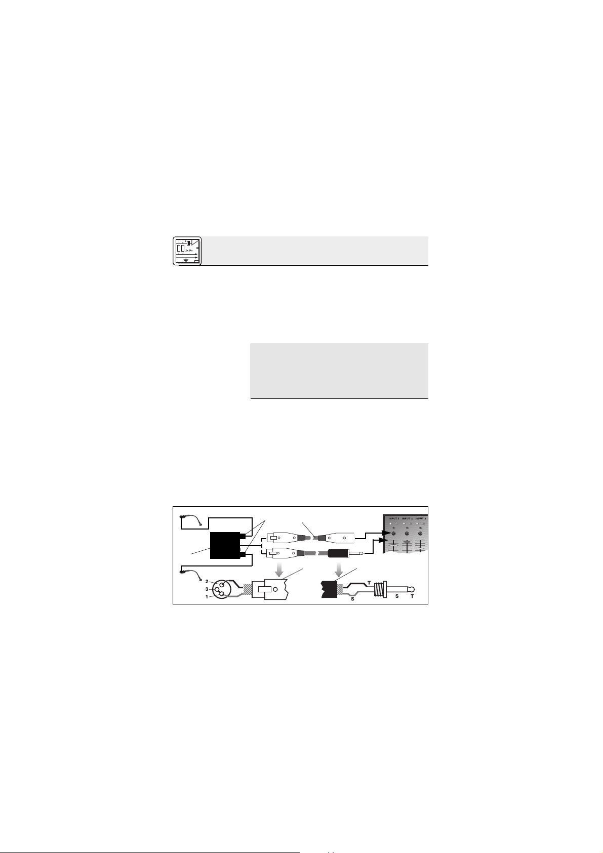
70
2 Conexión
Nota:
2.3 C 416
III
L
2.3.1 Conexión
utilizando el
B 29 L
Ver Fig. 3.
Conexión del
cable:
1. Una mediante un puente de alambre la espiga 1
del conector XLR (4) con la espiga 3 y con la
pantalla del cable.
2. Una el conductor interno del cable con la
espiga 2 del conector XLR (4) y la punta del
conector jack (5).
3. Una la pantalla del cable con el mango del
conector jack (5).
Los cables no balanceados pueden recoger interferencias de campos magnéticos (de los cables de red, de alumbrado, de motores eléctricos, etc.) igual que una antena. En los cables
de más de 5 m de largo, esto puede producir
ruidos de zumbido u otras perturbaciones.
Utilizando el alimentador por batería B 29 L opcional
puede conectar el micrófono a entradas balanceadas o no balanceadas sin alimentación fantasma.
1. Para conectar el micrófono al B 29 L, enchufe
el conector mini-XLR macho del cable del
micrófono (1) en uno de los dos conectores
mini-XLR hembra del B 29 L (2) introduciéndolo hasta que haga tope.
El conector macho (1) queda automáticamente
bloqueado.
Fig. 3: Esquema de conexión con B 29 L
B 29 L
Page 71
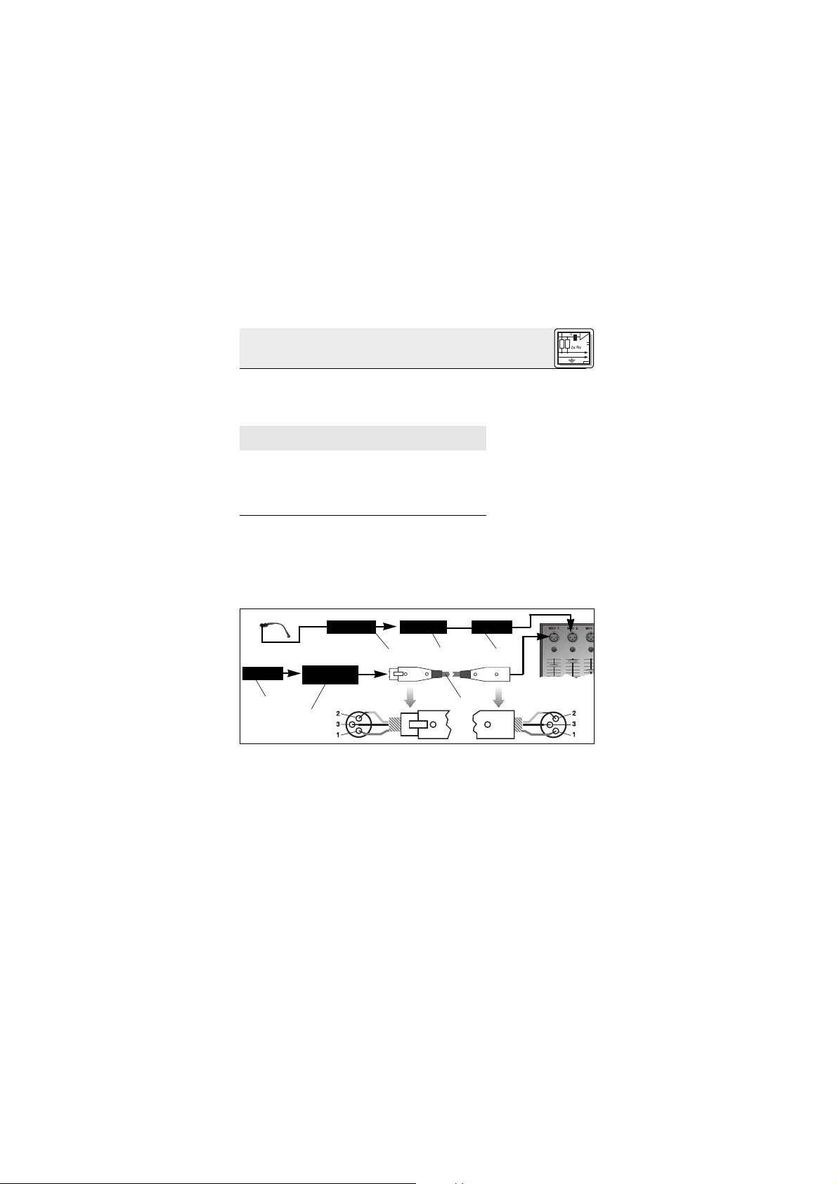
71
2 Conexión
Desconexión del
cable:
¡Importante!
Ver Fig. 3.
Entrada
balanceada:
Entrada no
balanceada:
2.3.2 Conexión
mediante el
MPA III L
Ver Fig. 4.
Desconexión del
cable:
Para desconectar el cable, presione el desbloqueador del conector mini-XLR macho (1) y separe el conector macho del cable del micrófono (1) del conector hembra del B 29 L (2).
¡No tire nunca del cable para desconectarlo porque lo puede dañar!
2. Conecte el B 29 L (2) a la entrada deseada.
• Para conectar el micrófono a una entrada
balanceada, utilice un cable XLR común (3)
en venta en cualquier tienda del ramo.
•Ver capítulo 2.2.2.
1. Enchufe el conector mini-XLR (1) del cable del
micrófono, hasta que llegue al tope, en el acoplamiento mini-XLR (2) en el cable de conexión
del MPA III L (3).
El conector (1) se enclava automáticamente.
Ver capítulo 2.3.1.
2. Conecte el adaptador de alimentación fantasma del cable del micrófono a una entrada
de micrófono XLR balanceada con alimentación fantasma.
3. Concecte la alimentación fantasma (consulte
para ello el Modo de empleo del aparato correspondiente).
Mini XLR Mini XLR MPA
MPA
Phantom
Fig. 4: Esquema de conexión con MPA III L
Page 72
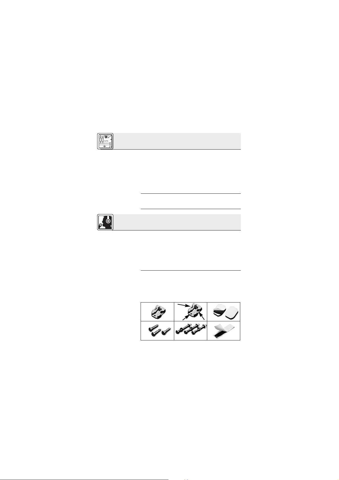
72
2 Conexión
Ver Fig. 4.
2.3.3 Conexión a
un emisor de
bolsillo
3.1 Introducción
3.2 Fijar el
micrófono
Fig. 5 Material de
montaje
4. Si su pupitre de mezclas no tiene ali-
mentación fantasma, enchufe el MPA III L
(3) al alimentador de tensión fantasma de AKG
opcional (4) (N 62 E, N 66 E, B 18, B 15) y
conecte luego el alimentador de tensión fantasma (4) a una entrada balanceada utilizando
un cable XLR (5) (por ej.: AKG MK 9/10 - no incluido en el suministro).
Consulte las instrucciones de uso de su emisor de
bolsillo.
Antes de fijar el micrófono en forma definitiva en el
instrumento o el cajón del altavoz, ensáyelo en distintos lugares par determinar el mejor sonido.
Para ello puede fijar el micrófono provisoriamente
con la masa adhesiva incluida.
Las posiciones más seguras y otras indicaciones de
uso las puede encontrar en los Capítulos 3.3. a 3.5.
El micrófono se puede fijar en forma permanente
en el instrumento o el cajón del altavoz o con fijación removible de encaje elástico.
Para ello el micrófono va acompañado de las piezas siguientes:
1 laminita de montaje H 416
3 Utilización
1 2 3
564
Page 73

73
3 Utilización
3.2.1 Montaje
con la laminita
de montaje
H 416
Fig. 6: Atornillar la
laminita de
montaje H 416
¡Importante!
2 3 manguitos de goma (integrados en la H 416)
3 2 plaquitas de goma con pegamento por am-
bos lados
4 3 tornillos cilíndricos para chapa, 2,9 x 13 mm
5 3 tornillos de cabeza plana con contratuerca,
3 x 30 mm
6 masa adhesiva
1. Fije la laminita de montaje H 416 en el insturmento o el cajón del altavoz.
Para ello tiene las siguientes posibilidades:
a) Fijación con tornillos:
•Dependiendo del espesor de pared y del material de la caja, utilice los tornillos cilíndricos
para chapa de 13 mm o los tornillos de cabeza
plana con contratuerca de 30 mm.
Al apretar los tornillos ponga cuidado en
que los manguitos de goma no se compriman.
Estos manguitos de goma constituyen el alojamiento elástico del micrófono y reprimen eficazmente, junto con el elemento atenuador de
elastómero integrado en el brazo del micrófono, la transmisión de ruidos mecanicos perturbadores. Si se comprimen los manguitos de
goma, se pierde la eficacia de este alojamiento
elástico.
Page 74

74
3 Utilización
Fig. 7 Plaquita de
goma con
pegamento por
ambos lados
Véase la Fig. 7.
Nota:
Fig. 8: Introducir el
micrófono en la
laminita de
montaje H 416
Véase la Fig. 8.
b) Fijación sin tornillos en superficies planas:
• Retire el papel recubridor de ambos lados de la
plaquita de goma y apriétela firmemente contra la laminita de montaje H 416 y el instrumento o el cajón del altavoz.
c) Fijación sin tornillos en superficies disparejas:
• En lugar de la plaquita de goma, utilice la masa
adhesiva incluida.
En estos dos casos (b y c), la compensación
del ruido corporal es igual que con la fijación
con tornillos.
2. Introduzca la brida del cuello de cisne en la laminita de montaje H 416 hasta que se enclave
en forma audible.
El micrófono se puede desmontar cuando sea
necesario, p.ej. para protejerlo contra daños
durante el transporte.
Page 75

75
3 Utilización
Fig. 9: Contratracción del cable
Véase la Fig. 9.
3.2.2 Montaje
fijo
Fig. 10 Atornillar el
micrófono directamente en el instrumento o el cajón
del altavoz
Véase la Fig. 10.
3. Coloque el cable en torno a los resaltes de la
laminita de montaje para reducir la tracción del
cable para el micrófono.
Para fijar el micrófono permanentemente en el instrumento o en el cajón del altavoz se cuenta con
las siguientes posibilidades:
A. Montaje con tornillos
1. Saque dos de los manquitos de goma de la laminita de montaje H 416 y páselos por la
ranura en la brida del cuello de cisne a las dos
perforaciones.
2. Dependiendo del espesor de pared y del material de la caja, utilice los tornillos cilíndricos
para chapa de 13 mm o los tornillos de cabeza
plana con contratuerca de 30 mm.
Page 76

76
3 Utilización
¡Importante!
Fig. 11: La masa
adhesiva como
protección contra
ruido vibracional
Nota:
Véase la Fig. 11.
Nota:
Para conservar la eficacia de la atenuación
de ruidos corporales de los manguitos de
goma, apriete los tornillos de tal forma que
no se compriman los manquitos.
Si ha montado el micrófono en una superficie
plana pegue la masa adhesiva debajo del elemento de atenuación del cuello de cisne. La masa
adhesiva reprime tanto las vibraciones del cuello
de cisne como el correspondiente ruido.
B. Fijación sin tornillos en superficies planas
• Retire al papel recubridor de ambos lados de la
plaquita de goma y péguela firmemente en la
brida y en el instrumento o el cajón del altavoz.
C.
Fijación sin tornillos en superficies disparejas
• Utilice la masa adhesiva incluida en lugar de la
plaquita de goma.
En estos dos casos (B y C), la compensación
del ruido mecanico es igual que con la fijación
con tornillos.
Page 77

77
3 Utilización
3.3 Acordeón
Fig. 12: Toma de
acordeón con dos
C 416
III
Véase la Fig. 12.
Para una toma óptima del acordeón se necesitan
dos micrófonos: uno para la gama de bajos y otro
para el tiple. El brazo flexible permite un emplazamiento exacto del micrófono en relación con el instrumento.
Para instrumentos más grandes, el C 416
III
puede
montarse también debajo del recubrimiento del
acordeón, recomendándose en este caso la utilización de la pantalla antiviento W 44 para reprimir ruidos de soplido producidos por el fuelle.
Conduzca los cables de los micrófonos a lo largo
de una de las correas y reúnalos en la espalda, llevándolos desde allí al alimentador por batería
B 29 L, a los emisores de bolsillo, al pupitre mezclador etc. para permitir en gran medida una ejecución no estorbada por cables.
Page 78

78
3 Utilización
Fig. 13: Toma de
acordeón con un
C 416
III
y un micró-
fono combinado
con soporte
Véase la Fig. 13.
3.4 Amplificador
de guitarra,
amplificador de
bajos, Leslie
Fig. 14: Amplifica-
dor de guitarra y
de bajos
Véase la Fig. 14.
Para la toma de acordeón con un C 416
III
y un
micrófono combinado con soporte proceda como
sigue:
1. Fije el C 416
III
en el lado de los bajos del acordeón y dirija el micrófono sobre una de las
aberturas acústicas.
2. Dirija el micrófono combinado con soporte
sobre los tiples del acordeón.
Emplace el micrófono fuera del centro de un altavoz para poder transmitir en forma natural el
"sound" típico del amplificador. Si el micrófono se
dirige directamente sobre el centro del altavoz, el
sonido puede resultar demasiado estridente.
Page 79

79
3 Utilización
3.5 Piano de
cola
Fig. 15: Toma del
piano de cola con
dos C 416
III
Véase la Fig. 15.
Para la toma de altavoces a dos o tres vías y también de Leslie deberían utilizarse dos micrófonos:
uno para el altavoz de tonos agudos y medianos y
otro para los bajos.
Para garantizar una transmisión neutral del sonido
deberían utilizarse dos micrófonos, debido a la
superficie de reflexión tan grande del piano.
Dirija un micrófono para la gama de bajos y el otro
para las frecuencias medianas y altas.
Limpie la caja del micrófono con un paño humedecido con agua.
4 Limpieza
Page 80
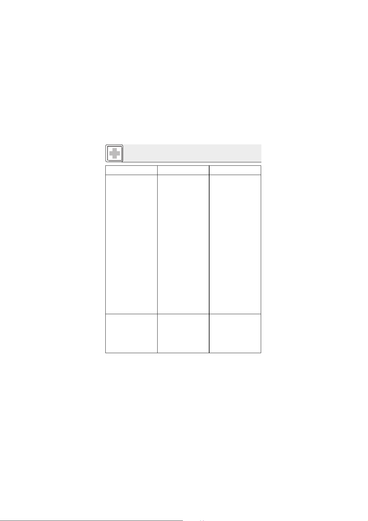
80
5 Eliminación de fallos
Fallo
No hay sonido:
Distorsiones:
Causa posible
1. Están desconectados:
el pupitre de mezcla
y/o el amplificador.
2. Están en cero: el fader
del canal o el regulador
del nivel de suma del
pupitre de mezcla o el
regulador de volumen
del amplificador.
3. El micrófono no está
conectado al pupitre de
mezcla o al amplificador.
4. Los conectores del cable no están bien enchufados.
5. El cable está dañado
(fallado, defectuoso).
6. No hay tensión de alimentación.
1. El nivel de ganancia de
la mesa de mezcla está
muy alto.
2. La entrada de la mesa
de mezcla es muy sensible.
Eliminación
1. Conectar el pupitre de
mezcla y/o el
amplificador.
2. Ajustar en el nivel deseado el fader, el regulador master del pupitre de mezcla o el regulador de volumen del
amplificador.
3. Conectar el micrófono
al pupitre de mezcla o
al amplificador.
4. Enchufar nuevamente
los conectores del cable.
5. Controlar el cable y renovarlo si es necesario.
6. Conecte la alimentación fantasma.
Alimentador de tensión
fantasma: conéctelo a
la red o coloque batería(s).
Controle el cable y, si
es necesario, reemplácelo.
1. Disminuya el nivel de
ganancia con el regulador de ganancia.
2. Conecte un preatenuador de 10 dB entre el
cable de micrófono y la
entrada.
Page 81
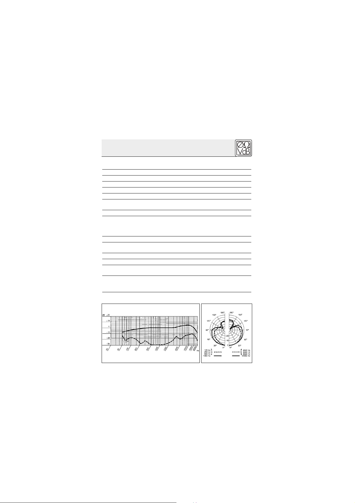
81
Modo de funcionamiento: Micrófono de condensador con carga per-
manente
Característica direccional: Hipercardioide
Gama de frecuencia: 20 - 20000 Hz
Sensibilidad: 7 mV/Pa (-43 dB referido a 1 V/Pa)
Impedancia eléctrica a 1000 Hz:
200 Ω
Impedancia de carga recomendada: ≥2000 Ω
Presión sonora límite para factor de distorsión
no lineal de 1% / 3%: 121 / 131 dB SPL
Nivel de ruido equivalente: 30 dB (A) (según DIN 45412)
Tensión de alimentación: C 416
III
PP: Al. fantasma universal 9 - 52 V
C 416
III
L: Alimentador por batería B 29 L,
adaptador fantasma MPA III L.
emisores de bolsillo AKG WMS
Toma de corriente: Aprox. 2 mA
Longitud del cable / conector: C 416
III
PP: 3 m / XLR de 3 polos
C 416
III
L: 1,5 m / mini-XLR de 3 polos
Superficie: Negro opaco
Dimensiones: 235 x 30 mm
Peso neto/bruto: C 416
III
PP: 120 g / 455 g
C 416
III
L: 55 g / 390 g
Este producto corresponde a la norma EN 50 082-1, siempre y cuando
los aparatos postconectados correspondan también a las normas CE.
Respuesta de frecuencia Diagrama polar
6 Datos técnicos
Page 82

82
1 Aviso de segurança/Descrição
1.1 Aviso de
segurança
1.2 Volume de
fornecimento
1.3 Acessórios
opcionais
Certifique-se de que o aparelho ao qual pretende
ligar o microfone está ligado à terra e que corresponde às normas de segurança.
Verifique se a embalagem contém todos os componentes acima indicados. Caso falte algo, favor
entre em contato com a concessionária da AKG.
1 x C 416
III
1x H 416 1 x W 44
3 parafusos de
cabeça
cilíndrica
(2,9 x 13 mm),
3 parafusos
com porcas
(3 x 30 mm)
2 placas de
borracha adesiva dupla face
Massa elástica
adesiva
• Cabo de microfone MK 9/10: cabo
blindado a dois polos de 10 m com plu-
gue XLR e tomada XLR.
• Adatador de alimentação fantasma
MPA III L (para C 416III L)
• Alimentador a pilhas B 29 L
(para C 416III L)
Page 83

83
1 Descrição
1.4
Características
especiais
1.5
Apresentação
• Microfone condensador robusto para captação instrumental em palcos.
•A resposta de freqüência é concebida especialmente para a captação do acordeão, de
amplificadores de guitarra/baixo e do piano.
• Alta segurança quanto à realimentação através da característica hipercardióide independente da freqüência.
•O pescoço de cisne de 100 mm possibilita o
direcionamento exato do microfone.
• Suspensão elástica do pescoço de cisne para
suprimir de forma eficaz os ruídos mecânicos.
• Paravento externo e acessórios para a montagem direta no instrumento ou na caixa amplificada estão incluídos na embalagem.
O C 416
III
é um microfone condensador com característica direcional hipercardióide. Foi desenvolvido
especialmente para a montagem direta em acordeões, alto-falantes de amplificadores de guitarra
ou baixo, pianos de cauda e verticais. Os parafusos
e elementos de fixação incluídos na embalagem
possibilitam montar o microfone de forma segura
no instrumento ou na caixa do alto-falante. Você
pode fixar ou o próprio microfone ou somente a
chapa de instalação H 416. O microfone encaixa-se
seguramente na chapa de instalação, mas pode ser
removido facilmente.
Um pescoço de cisne de 100 mm
de comprimento possibilita posicionar o microfone
de
maneira exata para obter o som perfeito.
• Alimentadores fantasma
N 62 E, N 66 E, B 18, B 15
(para C 416III PP)
Page 84

84
1 Descrição
1.6 1.6 Versões
C 416
III
PP
C 416
III
L
2.1 Introdução
Importante!
2.2 C 416
III
PP
2.2.1 Conexão a
entradas
balanceadas
Veja fig. 1.
O transdutor de condensador da alta qualidade
com característica direcional hipercardióide proporciona uma reprodução natural, bem detalhada, e fica muito insensível a realimentações
acústicas e diafonias de outros instrumentos posicionados ao lado.
Através do amortecedor de borracha incorporado
no pescoço de cisne o microfone é insensível aos
ruídos mecânicos do instrumento ou do alto-falante.
O microfone é disponível em duas versões:
• Para alimentação fantasma universal de 9 a
52 V. Cabo de conexão fixo de 3 m com adatador de alimentação fantasma com conetor
XLR tripolar integrado.
• Para a ligação ao alimentador a pilhas B 29 L,
adatador de alimentação fantasma MPA III L
ou a emissores de bolso AKG.WIRELESS.
Cabo de conexão de 1,5 m com conetor miniXLR tripolar travador.
O C 416
III
é um microfone de condensador e por
isso precisa de uma alimentação de corrente.
Se usar outros alimentadores senão aqueles recomendados pela AKG, o microfone
pode ser danado e caduca a garantia.
1. Conete o adatador de alimentação fantasma
(1) no cabo a uma entrada de microfone XLR
com alimentação fantasma.
2. Ligue a alimentação fantasma. (Veja as instruções de uso do equipamento ao qual o
microfone está ligado.)
2 Conexão
Page 85

85
2 Conexão
Veja fig. 1.
2.2.2 Conexão a
entradas não
balanceadas
Veja fig. 2.
3. Se a sua mesa de mixagem não possuir
uma alimentação fantasma, ligue o adaptador de alimentação fantasma (1) a um alimentador fantasma opcional da AKG (2) (N 62 E,
N 66 E, B 18, B 15) e ligue o alimentador fantasma a uma entrada balanceada com um
cabo XLR (3) (por exemplo AKG MK 9/10 - não
fornecido na embalagem).
Pode conetar os alimentadores fantasma (2) da AKG
a uma entrada ou balanceada ou não balanceada.
Use um cabo (3) com um conector XLR fêmea e
um plug banana mono:
Fig. 1: Conexão a uma entrada balanceada
Phantom
MPA
MPA
Fig. 2: Conexão a uma entrada não balanceada
PhantomMPA
Page 86
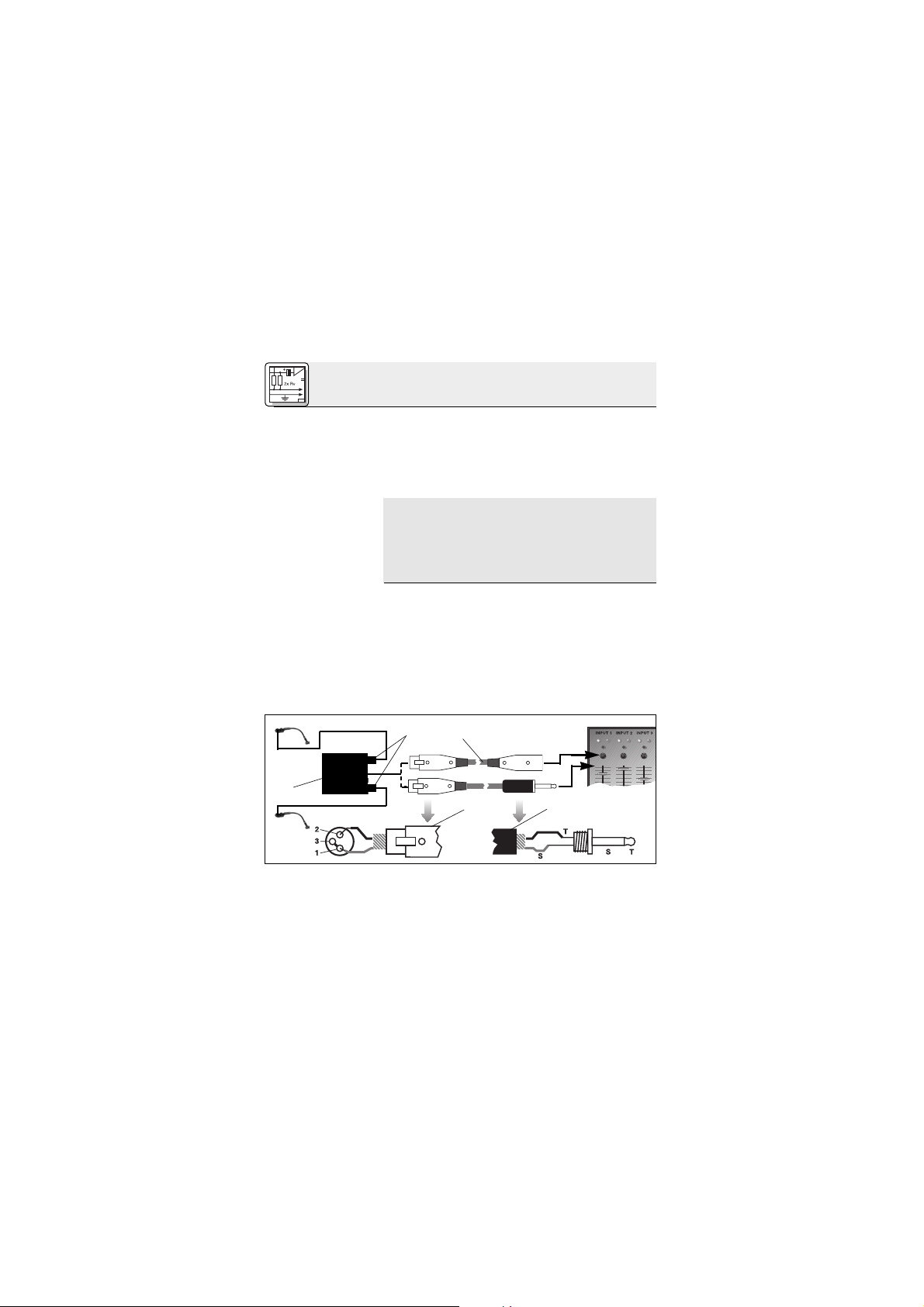
86
2 Conexão
Obs.:
2.3 C 416
III
L
2.3.1 Conexão
através do
B 29 L
Ligar o cabo:
Veja fig. 3.
Tirar o cabo:
1. Solde em ponte os pinos 1 e 3 no conetor XLR
(4) e conete à malha do cabo.
2. Conete o núcleo do cabo com o pino 2 do conetor XLR (4) e com a ponta do plug banana (5).
3. Conete a malha do cabo com a aste do plug banana (5).
Os cabos não balanceados podem absorver
radiações de campos magnéticos (cabos de
rede, cabos de iluminação, motores elétricos,
etc.) como uma antena. Em cabos com mais
de 5 m de comprimento isto poderá levar a
zumbidos e outros ruídos.
Com o alimentador a pilhas opcional B 29 L pode
ligar o microfone a entradas balanceadas ou não
balanceadas sem alimentação fantasma.
1. Coloque o conetor mini-XLR (1) do cabo do
microfone numa das duas entradas mini-XLR
no B 29 L (2) até atingir o ponto final.
O conetor (1) é travado automaticamente.
Para tirar o cabo pressione o botão de destrava no conetor mini-XLR (1), tirando o conetor (1) da entrada.
Fig. 3: Esquema de conexão com B 29 L
B 29 L
Page 87

87
2 Conexão
Importante!
Entrada
balanceada:
Veja fig. 3.
Entrada não
balanceada
2.3.2 Como usar
o MPA III L
Ligar o cabo:
Veja fig. 4.
Tirar o cabo:
Veja fig. 4.
Para não prejudicar o cabo, nunca o tire segurando o próprio cabo!
2. Ligue o B 29 L (2) à entrada desejada.
• Para ligar a uma entrada balanceada utilize
um cabo XLR (3) comum.
•Veja capítulo 2.2.2.
1. Insera até ao encosto o conetor mini-XLR (1)
fixado ao cabo do microfone na tomada miniXLR (2) do cabo de conexão do MPA III L (3).
O conetor (1) é travado automaticamente.
Veja capítulo 2.3.1.
2. Conete o MPA III L (3) a uma entrada de microfone XLR com alimentação fantasma.
3. Ligue a alimentação fantasma. (Veja as instruções de uso do equipamento ao qual o
microfone está ligado.)
4. Se a sua mesa de mixagem não possuir
uma alimentação fantasma, ligue o MPA III L
(3) a um alimentador fantasma opcional da
AKG (4) (N 62 E, N 66 E, B 18, B 15) e ligue o alimentador fantasma a uma entrada balanceada
Mini XLR Mini XLR MPA
MPA
Phantom
Fig. 4: Esquema de conexão com MPA III L
Page 88

88
2 Conexão
2.3.3 Ligar a um
emissor de bolso
3.1 Introdução
3.2 Montar o
microfone
Fig. 5: Material de
montagem
com um cabo XLR (5) (por exemplo AKG
MK 9/10 - não fornecido na embalagem).
Leia o manual do seu emissor de bolso.
Antes de instalar o microfone definitivamente verifique vários posicionamentos para descobrir
onde ele soa melhor. Para isso, fixe o microfone
provisoriamente com amassa elástica adesiva
fornecida na embalagem.
As técnicas de captação aprovadas descritas nos
capítulos 3.3 a 3.5 poderão servir de ponto de referência.
Pode montar o microfone no instrumento ou no
falante ou permanentemente ou por meio de uma
conexão de encaixamento destacável.
Para isso, as seguintes partes são incluídas na
embalagem do microfone:
1 Chapa de instalação H 416
2 3 buchas de borracha (inseridas no H 416)
3 2 placas de borracha adesiva dupla face
3 Aplicação
1 2 3
564
Page 89
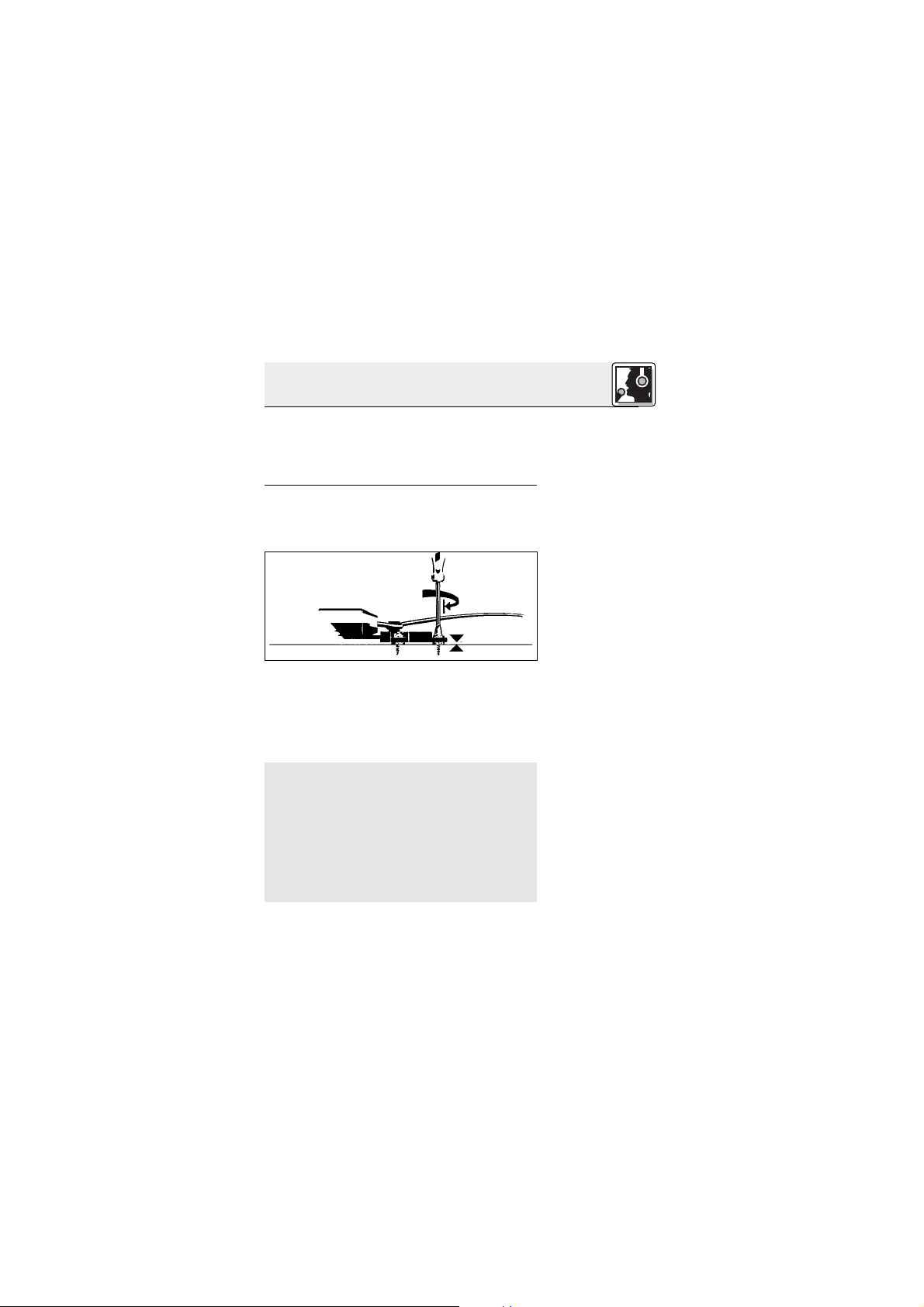
89
3 Aplicação
3.2.1 Montagem
por meio do
H 416
Fig. 6: Parafusar o
H 416.
Veja fig. 6.
Importante!
4 3 parafusos auto-roscantes de cabeça cilín-
drica (2,9 x 13 mm)
5 3 parafusos de cabeça chata com porcas (3 x
30 mm)
6 Massa elástica adesiva
1. Fixe a chapa de instalação H 416 no instrumento ou na caixa amplificada em uma das seguintes maneiras:
a) Montagem com parafusos:
• Dependendo do material e espessura do
corpo você pode fixar o H 416 ou com os parafuso de 13 mm ou com os parafusos e porcas
de 30 mm incluídos na embalagem.
Certifique-se de que o microfone está firmemente seguro no lugar sem as buchas
de borracha sendo excessivamente apertados.
Essas buchas juntas com o amortecedor de
borracha incorporado no pescoço de cisne suprimem eficazmente a transmissão de ruído
mecânico. Se as buchas forem excessivamente apertados, perderiam a sua eficácia
como amortecedores de ruído.
Page 90

90
3 Aplicação
Fig. 7: Placa de
borracha adesiva
dupla face
Veja fig. 7.
Obs.:
Fig. 8: Inserir o
microfone
no H 416
Veja fig. 8.
b)
Montagem sem parafusos em superfícies planas:
• Remova a folha de proteção de ambos os lados da borracha e pressione-a firmemente no
H 416 e então no instrumento ou falante.
c) Montagem sem parafusos em superfícies irre-
gulares:
• Use a massa adesiva incluída na embalagem
em vez da placa de borracha.
A atenuação de ruído mecânico é a mesma em
ambos os casos (b e c) que no caso da montagem com parafusos.
2. Insira o suporte do pescoço de cisne na chapa
de instalação H 416 até o suporte se encaixa
audivelmente.
Pode remover o microfone em qualquer momento, por exemplo, a fim de preveni-lo de da-
Page 91
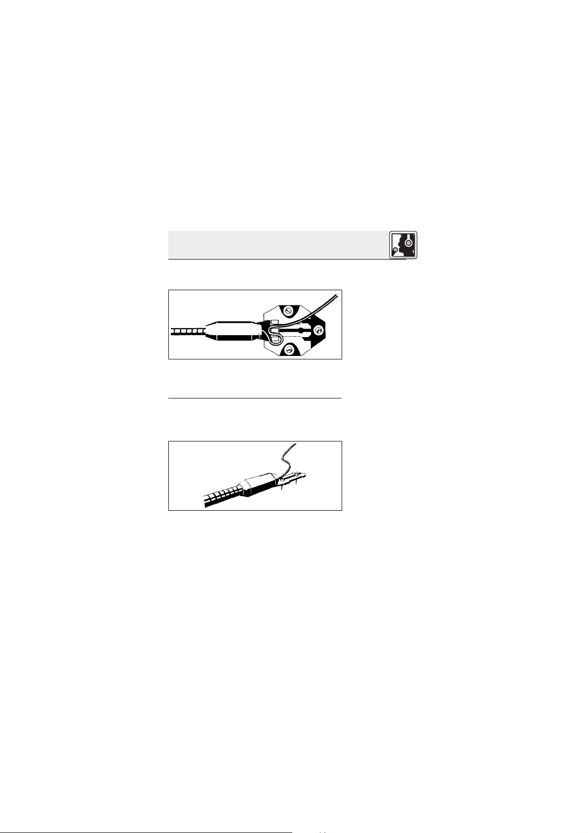
91
3 Aplicação
Fig. 9: Trava cabo
Veja fig. 9.
3.2.2 Montagem
permanente
Fig. 10: Parafusar o
microfone diretamente no instrumento/falante
Veja fig. 10.
nos quando transportando o instrumento ou a
caixa amplificada.
3. Coloque o cabo em volta das barbatanas na
chapa de instalação para aliviar o microfone da
tensão do cabo.
Pode montar o microfone permanentemente no
instrumento ou no falante numa das seguintes
maneiras:
A. Montagem com parafusos
1. Remova duas das buchas na chapa de instalação do H 416 e insira-as nos buracos no
suporte, deslizando-os através da abertura.
2. Dependendo do material e espessura do
corpo, fixe o microfone ou com os parafuso de
13 mm ou parafusos e porcas de 30 mm incluídos na embalagem.
Page 92

92
3 Aplicação
Importante!
Fig. 11: Massa
adesiva como
proteção contra a
chacoalhada
Obs.:
Veja fig. 11.
Obs.:
Para mantêr a supressão de ruído mecânico das buchas de borracha, certifique-se
de que o microfone está firmemente seguro
no lugar sem as buchas de borracha sendo
excessivamente apertadas.
Quando montado em superfícies planas, o
microfone pode chacoalhar devido as vibrações. Neste caso, coloque um pouco da
massa elástica adesiva entre a superfície e a
base do pescoço de cisne. A masse adesiva
suprime as vibrações do pescoço de cisne e a
chacoalhada resultante.
B. Montagem sem parafusos em superfícies
planas
• Remova a folha de proteção de ambos os lados da borracha e pressione-a firmemente no
H 416 e então no instrumento ou falante.
C. Montagem sem parafusos em superfícies
irregulares
• Use a massa adesiva incluída na embalagem
em vez da placa de borracha.
A atenuação de ruído mecânico é a mesma em
ambos os casos (B e C) que no caso da montagem com parafusos.
Page 93

93
3 Aplicação
3.3 Acordeão
Fig. 12: Microfonar
o acordeão com
dois C 416
III
Veja fig. 12.
Para microfonar o acordeão com bons resultados,
você irá precisar de dois microfones, um para a
região de graves e um para a região de agudos. O
pescoço de cisne permite posicionamento preciso.
Se o seu instrumento é muito grande, você pode
ainda instalar o microfone dentro do corpo, certificando-se de colocar o paravento W 44 para suprimir o ruído de vento criado pelos foles.
Coloque os cabos dos microfones ao longo de
uma das correias e conete os cabos ao alimentador a pilhas B 29 L, aos emissores de bolsa, à
mesa de mixagem, etc. Desta maneira os cabos
não disturbarão quando você está tocando.
Page 94

94
3 Aplicação
Fig. 13: Microfonar
o acordeão com
um C 416
III
e um
microfone fixado
em tripé
Veja fig. 13.
3.4 Caixa
Amplificada de
Baixo e
Guitarra, Caixa
Leslie
Fig. 14: Amplifica-
dor de guitarra ou
baixo
Veja fig. 14.
Alternativamente, pode microfonar o acordeão
com um C 416
III
e um microfone fixado em tripé:
1. Fixe o C 416
III
na caixa dos baixos do acordeão
e direcione o microfone para um dos orifícios
para a saída do som.
2. Direcione o microfone fixado em tripé para a
caixa do teclado do acordeão.
Coloque o microfone um pouco fora do centro de
um falante a fim de capturar precisamente o som
do amplificador. Quando direcionar o microfone
exatamente para o centro do falante o som pode
tornar-se exccessivamente agudo.
Para colunas de duas ou três vias e caixas Leslie,
Page 95

95
3 Aplicação
3.5 Piano de
cauda
Fig. 15: Microfonar
o piano de cauda
com dois C 416
III
Veja fig. 15.
use dois microfones, um para os falantes de agudos e de médios e um para o falante de graves.
Por ser o piano uma fonte sonora bastante
grande, você deverá usar dois microfones a fim de
assegurar reprodução neutra.
Direcione um microfone para a região grave e o
outro para a região aguda.
Limpe a carcaça do microfone com um pano
molhado em água.
4 Limpeza
Page 96

96
5 Resolver problemas
Problema:
Não há som:
Distorções:
Causa possível:
1. A mesa de mixagem
e/ou o amplificador
está desligado.
2. O fader do canal do
microfone ou o regulador do nível total na
mesa de mixagem ou
o regulador de volume no amplificador
está em zero.
3. O microfone não está
ligado à mesa de
mixagem ou ao amplificador.
4. O plugue do cabo
não está ligado corretamente.
5. O cabo está com defeito.
6. Não há tensão de alimentação.
1. O nível do regulador
Gain na mesa de
mixagem é demasiadamente alto.
2. A entrada na mesa de
mixagem é demasiadamente sensível.
Resolução:
1. Ligar a mesa de
mixagem e/ou o amplificador.
2. Ajustar o fader do canal ou o regulador do
nível total na mesa de
mixagem ou no amplificador ao nível desejado.
3. Ligar o microfone à
mesa de mixagem ou
ao amplificador.
4. Ligar o plugue do
cabo mais uma vez.
5. Controlar o cabo e
substituir se for necessário.
6. Ligar a alimentação
fantasma.
Alimentador fantasma: ligar à rede ou
colocar a(s)pilha(s).
Verificar o cabo e
substituir, se for
necessário.
1. Baixar o nível do regulador gain.
2. Colocar um preatenuador de 10 dB
entre o cabo de
microfone e a
entrada.
Page 97

97
Tipo: microfone de condensador com carga
permanente
Caraterística direccional: hipercardióide
Resposta de freqüência: 20 - 20.000 Hz
Sensibilidade: 7 mV/Pa (-43 dBV ref. a 1 V/Pa)
Impedância elétrica: 200 Ω
Impedância de carga recomendada: ≥2000 Ω
Pressão sonora limite para
1% / 3% de distorsão: 121 / 131 dB SPL
Nível equivalente de ruído: 30 dB (A) (conforme DIN 45412)
Tensão de alimentação: C 416
III
PP: 9 a 52 V (al. fantasma universal)
C 416
III
L: Alimentador por pilhas B 29 L,
adatador fantasma MPA III L,
emissores de bolso WMS da AKG
Consumo de corrente: aprox. 2 mA
Tipo de conetor: C 416
III
PP: XLR tripolar
C 416
III
L: mini-XLR tripolar
Superfície: preto mate
Dimensões: 235 x 30 mm
Peso líquido/: C 416
III
PP: 120 g / 455 g
C 416
III
L: 55 g / 390 g
Este produto corresponde à norma EN 50 082-1 contanto que os equipamentos conetados correspondam às normas CE.
Resposta de freqüência Diagrama polar
6 Especificações
Page 98

98
Notizen - Notes - Notes - Note - Notas - Notas
Page 99

99
Notizen - Notes - Notes - Note - Notas - Notas
Page 100
Printed in Austria on recycled paper. 05/02/9100 U 1035
Technische Änderungen vorbehalten. Specifications subject to change without notice. Ces caractéristiques sont susceptibles de modifications.
Ci riserviamo il diritto di effettuare modifiche tecniche. Nos reservamos el derecho de introducir modificaciones técnicas. Especificações sujeitas à mudanças sem aviso prévio.
Mikrofone · Kopfhörer · Drahtlosmikrofone · Drahtloskopfhörer · Kopfsprechgarnituren · Akustische Komponenten
Microphones · Headphones · Wireless Microphones · Wireless Headphones · Headsets · Electroacoustical Components
Microphones · Casques HiFi · Microphones sans fil · Casques sans fil · Micros-casques · Composants acoustiques
Microfoni · Cuffie HiFi · Microfoni senza filo · Cuffie senza filo · Cuffie-microfono · Componenti acustici
Micrófonos · Auriculares · Micrófonos inalámbricos · Auriculares inalámbricos · Auriculares con micrófono · Componentes acústicos
Microfones · Fones de ouvido · Microfones s/fios · Fones de ouvido s/fios · Microfones de cabeça · Componentes acústicos
AKG Acoustics GmbH
Lemböckgasse 21–25, P.O.B. 158, A-1230 Vienna/AUSTRIA, Tel: (43 1) 86 654-0*, Fax: (43 1) 86 654-7516,
http://www.akg.com, e-mail: sales@akg.com
AKG Acoustics GmbH
Bodenseestraße 228, D-81243 München/GERMANY, Tel: (089) 87 16-0, Fax: (089) 87 16-200,
http://www.akg-acoustics.de, e-mail: info@akg-acoustics.de
AKG ACOUSTICS, U.S.
914 Airpark Center Drive, Nashville, TN 37217, U.S.A., Tel: (615) 620-3800, Fax: (615) 620-3875,
http://www.akgusa.com, e-mail: akgusa@harman.com
For other products and distributors worldwide see our website: http://www.akg.com
 Loading...