

Page 1
Bedienungshinweise
User Instructions
Mode d’emploi
Istruzioni d’uso
Modo de empleo
Instruções de Uso
C 391B
SE 300 B
Page 2

2
Einleitung:
Das C 390 System ist ein Komplettsystem, das sich in höchst praktischer und wirtschaftlicher Weise den sich stets ändernden Erfordernissen der Schallplatten-, Rundfunk-, Beschallungs- und Filmindustrie
anpassen kann. Damit steht dem T ontechniker eine ganze Palette von
Mikrofonmodulen zur Verfügung, die für jede er denkliche Anwendung
zu „maßgeschneiderten“ Mikrofonen mit Studioqualität kombiniert
werden können.
Beschreibung:
Das C 390 System besteht aus einem Universal-Speiseteil/Ausgangsmodul (SE 300 B), 8 verschiedenen Mikrofonkapseln sowie leicht
kombinierbaren Zubehörteilen, um allen Anwendungssituationen gerecht zu werden. Eine Übersicht des Gesamtsystems finden Sie auch
am Schluß dieser Anleitung.
Die Hauptmerkmale des Systems sind:
• robuste Mechanik
• geringes Eigenrauschen
• geringer Strombedarf
• hohe Betriebssicherheit
• niederohmiger Kapselanschluß
• einwandfreie Funktion bis 60° C und 95 % relative Luftfeuchtigkeit
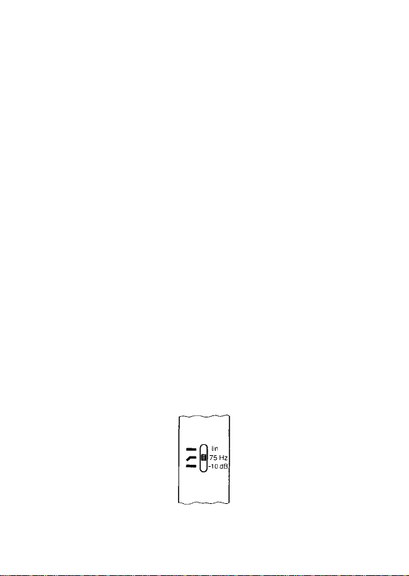
• eingebaute, schaltbare Abschwächung der Verstärkung um 10dB
(siehe Abb. 1)
• außergewöhnliche Langzeitstabilität
• trafolose Ausgangsstufe
• Speisung durch jede Phantomspeiseeinrichtung nach DIN 45596
möglich
• geringe Verzerrungen auch bei hohem Schalldruck
• eingebautes Baßfilter mit Einsatzpunkt des Filters bei ca. 100 Hz
(siehe Abb. 1)
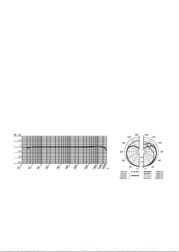
Abb. 1
Page 3
3
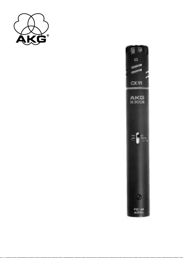
Das C 391 B besteht aus folgenden Modulen und T eilen:
• SE 300 B Speiseteil/Ausgangsmodul
• CK 91 Mikrofonkapsel mit frequenzunabhängiger , nier enförmiger
Richtcharakteristik
• W 90 Schaumstoffwindschutz
• SA 40 universeller Stativanschluß
Das Mikrofon ist aufgrund seiner leichten Membrane weitgehendst
unempfindlich gegen Hantiergeräusche. W eitere Merkmale sind das
Ganzmetallgehäuse und dadurch die geringe HF-Störungsanfälligkeit
sowie der problemlose Betrieb unter nahezu allen Bedingungen
aufgrund der konservativen und verläßlichen Konstruktion.
Die einschaltbare Abschwächung des Ausgangssignals um 10 dB wird
insbesondere im Zusammenhang mit hohen Schalldrücken (bei Verwendung im Nahbereich von energiereichen Schallquellen) und bei
Eingangsstufen von Verstärkern oder Mischpulten mit begrenztem
maximalen Eingangspegel von Vorteil sein, da sonst bereits eine Übersteuerung dieser angeschlossenen Stufen erfolgt, ohne daß die Aussteuerfähigkeit des Mikrofons voll genutzt wird.
Die am Mikrofon einschaltbare Baßabschwächung hilft zusätzlich,
Verzerrungen bei den tiefsten Frequenzen hintanzuhalten, die in unkontrollierter Weise z.B. dur ch Rumpel- oder Windgeräusche auftreten
können. Die Steilheit des Filters beträgt ca. 12 dB/Oktave, wobei die
Eckfrequenz (–3 dB Punkt) bei ca. 75 Hz liegt.
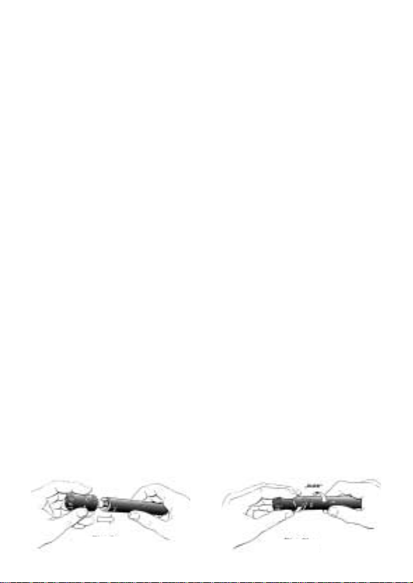
Handhabung:
Die Kapseln sind durch einen einfachen Bajonettverschluß mit dem
Speiseteil/Ausgangsmodul verbunden. Dies ermöglicht ein sicheres,
rasches und problemloses T auschen der unterschiedlichen Kapseln,
auch ohne Sicht, z. B. in abgedunkelten Räumen.
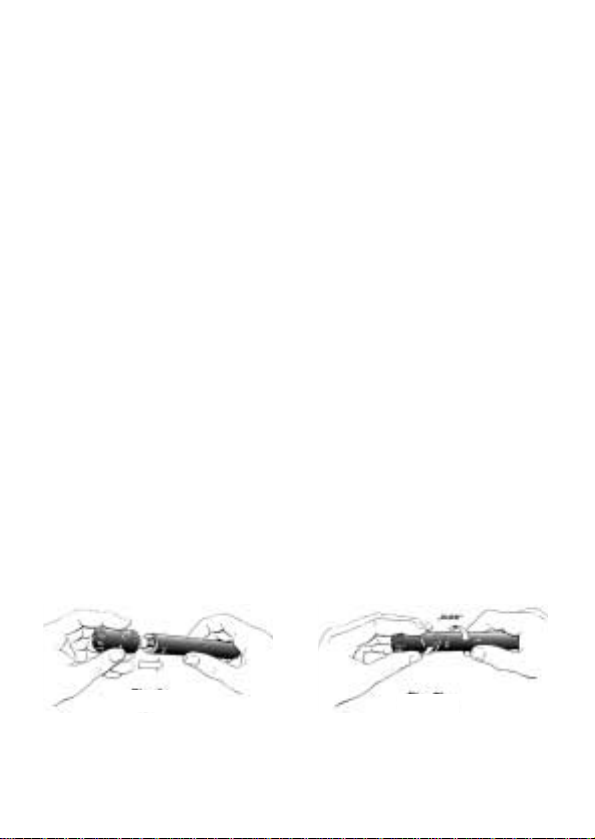
Die Kapseln bzw. diverse Zubehörteile sind nur in einer Position mit
dem Speiseteil zusammenführbar . Danach wird durch eine kurze und
kräftige Rechtsdrehung, bei der auch ein deutliches „Klick“ hörbar wird,
das Modul in seine Endposition gebracht (siehe Abb. 2a, 2b).
Durch eine kurze Linksdrehung ist das Kapselmodul ebenso wieder
rasch vom Speiseteil lösbar .
Abb. 2b
Abb. 2a
Page 4

4
Anwendungen:
Mit den von uns angebotenen Modulen und dem Systemzubehör kann
auf eine Vielzahl von anwenderspezifischen Situationen eingegangen
werden. Aus Platzgründen kann allerdings nur eine Auswahl davon
nachfolgend angeführt werden.
A) Auswahl von Kapselmodulen, um sich an unterschiedliche
akustische Verhältnisse und Aufgaben anzupassen:
CK 91 – Nierenmikrofonkapsel
Klassische Mikrofonkapsel mit nierenförmiger Richtcharakteristik; universell einsetzbar für alle Anwendungsgebiete, wo eine gute Dämpfung
von hinten (180°) gefordert wird.
CK 92 – Kugelmikrofonkapsel
Mikrofonkapsel mit kugelförmiger Richtcharakteristik zum Einsatz bei
Reportagen oder bei Chor- und Sologesangsaufnahmen im Ton- oder
Fernsehstudio. Die Kapsel hat – physikalisch bedingt – keine abstandsabhängige Frequenzkurve (Naheffekt), was bei den angeführten Anwendungen meist von Vorteil ist.
CK 93 – Hypernierenmikrofonkapsel
Im Aufbau ähnlich der CK 91, jedoch ist die Kapsel akustisch auf eine
gleichförmige Hypernieren-Charakteristik abgestimmt. Daraus resultiert
ein höherer Bündelungsgrad gegenüber der Nierenmikrofonkapsel.
Dies bietet Vorteile bei Mehrkanalaufnahmen durch besser e seitliche
T rennung bzw . in der Beschallung durch eine erhöhte Rückkopplungssicherheit.
CK 94 – Achtermikrofonkapsel
Diese Mikrofonkapsel zeichnet sich durch eine besonders gute Schallausblendung von der Seite aus und kann deshalb vorteilhaft bei Interviews oder Dramaaufnahmen eingesetzt werden. Eine weitere Anwendungsmöglichkeit bietet sich durch die Verwendung eines zweiten
Mikrofons der Serie mit Nieren-, Hypernieren- oder Kugelcharakteristik,
um als M/S-Kombination eingesetzt zu werden.
CK 97-O – Miniatur-Kugelmikrofonkapsel
Ein sehr universell verwendbares Miniaturmikrofon kleinster Abmessungen mit kugelförmiger Richtcharakteristik. Generell für Sprache, aber
auch zur akustischen Abnahme von Musikinstrumenten geeignet.
Page 5
5
CK 97-C – Miniatur-Nierenmikr ofonkapsel
Dieses Miniaturmikrofon ist überall dort einsetzbar , wo es darauf
ankommt, daß das Mikrofon sich möglichst unauffällig ins Aufnahmegeschehen einfügt bzw. überhaupt nicht sichtbar sein soll. Trotzdem
sorgt die Richtcharakteristik des Mikrofons dafür , daß die Aufnahme fr ei
von überbetonter Räumlichkeit ist oder eine Beschallungsaufgabe mit
guter Rückkopplungssicherheit erfüllt werden kann.
CK 98 – kurze Richtrohrkapsel
Diese Richtrohrkapsel stellt einen guten Kompromiß zwischen Richtrohrlänge und erreichter Richtwirkung dar . Auf diese W eise ist die
Kapsel sehr gut für T onaufnahmen bei Film und Fernsehen sowie für
Anwendungen auf der Bühne und im Freien geeignet. Weiters überall
dort, wo es auf deutliche T rennung einzelner Instrumente ohne zusätzliche akustische T rennwände ankommt.
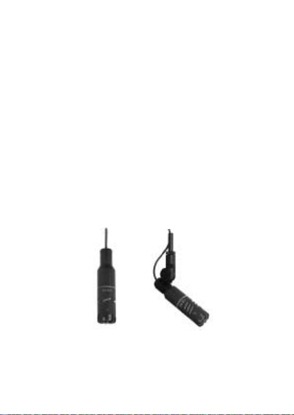
B) Verwendung des V erlängerungskabelsets MK 90/3 + H 98
Dieser Zubehörteil ermöglicht es dem T oningenieur in Film- und Fernsehstudios oder Theatern, die relativ kleinen Mikrofonkapseln örtlich
getrennt von den wesentlich größeren Mikrofon-V orverstärkern über
eine hochflexible Kabelverbindung einzusetzen. Einige Anwendungsbeispiele sind als Anregung nachfolgend abgebildet.
Page 6
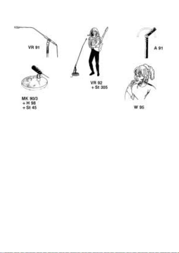
C) Der Einsatz des übrigen Systemzubehörs ist aus den folgenden
Abbildungen erkennbar .
Mitgeliefertes Zubehör:
SA 40 Elastischer Stativanschluß
W90Schaumstoffwindschutz (nur bei C391 B)
Empfohlenes Zubehör:
a) Systemzubehör:
A 91: Schwenkgelenk mit Schwenkbereich von ±90°von der Mikrofon-
achse
MK 90/3 + H 98: 3 m Adapterkabel einschließlich Stativanschluß/Auf-
hängevorrichtung
VR 91: 350 mm langes Verlängerungsrohr um alle Kapseln der Serie
vom Speiseteil/Ausgangsmodul absetzen zu können
VR 92: wie VR 91, jedoch mit kurzem Schwanenhalsstück und 1,2 m
lang
W 95: Ganzmetallwindschutz mit doppelter Schaumstoffauskleidung
für die Kapseln CK 91, CK 92 und CK 93
6
Page 7
7
b) Zubehör aus dem allgemeinen Lieferprogramm:
B 18: Batteriespeisegerät zum Betrieb von einem Mikrofon
H 10: Ganzmetall-Stereoschiene mit verstellbarem Abstand zwischen
den Mikrofonen von 35 bis 78 mm
H 30: Elastische Halterung mit sehr guter Dämmung
H 38: Elastische Halterung zum Betrieb des Mikrofons auf Video- oder
Filmkameras
H 52: Stereo-Halterungsset zum optisch unauffälligen Stereobetrieb
zweier Kapseln des Systems in XY (Koinzidenz), M/S- oder ORTFTechnik
N62E:Netzgerät zum Betrieb von 2 Mikrofonen
N66E:Netzgerät zum Betrieb von 6 Mikrofonen
SA 18/1 B: Ganzmetall-Stativanschluß für besonders stabile Klemmung
des Mikrofons
SA 38/H: Schwenkbarer Stativanschluß mit montierter elastischer
Halterung H 38
St 45: Kleines Tischstativ
St 46: Kleines Tischstativ zum Betrieb der abgesetzten Kapseln
St 305: Schweres Tischstativ mit rundem Sockel und Gummiauflage
zur Dämmung von Körperschall
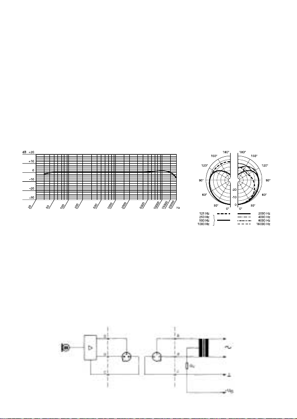
Frequenzkurve: Polardiagramm:
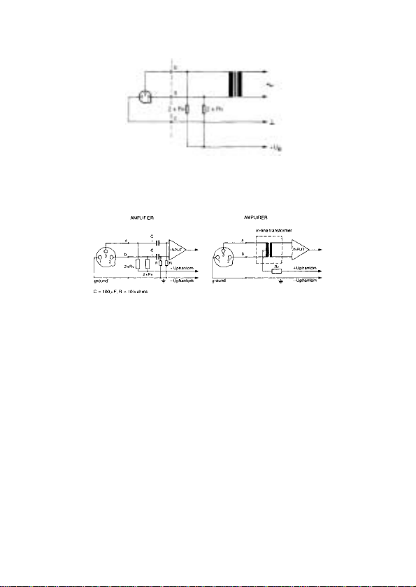
Speisetechnik:
Der Speiseteil/Ausgangsmodul kann aus Phantomspeisequellen nach
DIN 45596 gespeist werden. Diese Norm schreibt eine positive Spannung von 12, 24 oder 48 Volt an den NF-Leitungen gegen die Kabelabschirmung vor .
Page 8
8
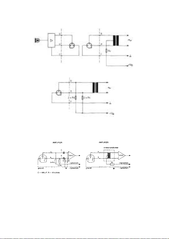
Folgende Anschlußschemata werden empfohlen:
1. Schaltung mit Eingangsübertrager mit Mittenanzapfung (erdfrei):
2. Schaltung mit Eingangsübertrager ohne Mittenanzapfung (erdfrei):
3. Sind die Verstärkereingänge geer det oder keine Eingangsübertrager
vorhanden, müssen entweder Kondensatoren oder zusätzliche
T ransformatoren in die NF-Leitungen eingefügt werden, um eine Beeinträchtigung der Eingangsstufe durch Leckströme zu verhindern.
Diese Schaltung kann sehr einfach und relativ preisgünstig in fast
alle bestehenden Schaltungen nachträglich eingebaut werden und
erspart die Anschaffung von externen Speisegeräten.
Normwerte für Rv (oder 2 x Rv) sind:
+ UB Rv 2 x Rv
12 V ± 2 V 330 Ohm 680 Ohm
24 V ± 4 V 680 Ohm 1200 Ohm
48 V ± 4 V 3300 Ohm 6800 Ohm
Page 9

9
Bemerkung:
Die Widerstände 2 x Rv sollten im Wert zumindest innerhalb von 0,5 %
T oleranz sein, damit die geforderten Symmetriebedingungen erfüllt
werden.
Reinigungshinweise:
Alle Oberflächen können von Zeit zu Zeit problemlos mit (Industrie-)Spiritus oder Alkohol gereinigt werden. Der Schaumstoffwindschutz
wird am besten mit einer milden Waschmittellösung gereinigt und ist
sofort nach dem T rocknen wieder einsatzbereit.
T echnische Daten des C 391 B:
Elektrische Arbeitsweise: Kondensatormikrofon, selbst-
polarisiert
Akustische Arbeitsweise: Druckgradientenempfänger
Richtcharakteristik: Niere
Übertragungsbereich: 20–20.000 Hz ±2 dB von Sollkurve
Feld-Leerlaufübertragungsfaktor 10 mV/PaⳎ– 40 dBV bez. auf
(Empfindlichkeit) bei 1000 Hz: 1 V/Pa
Elektrische Impedanz: 200Ohm
Empfohlene Lastimpendanz:
1000 Ohm
Ersatzgeräuschpegel nach
DIN 45405 (CCIR 468-2): 26 dB
Äquivalentschalldruckpegel
nach DIN 45412 (A-bew.): 17 dB-A
Geräuschpegelabstand
bez. auf 1 Pa (A-bew.): 77 dB
Grenzschalldruck: 80 PaⳎ132 dB für 1000 Hz,
2000 Ohm Lastimpedanz und 1 %
Klirrfaktor
250 PaⳎ142 dB mit 10 dB Vorab-
schwächung
Betriebstemperatur: –20° C bis +60° C
Relative Luftfeuchte: 99% (+20° C), 95% (+60° C)
Speisespannung: 9–52 Volt nach DIN 45596
Strombedarf: 2mA
Abmessungen: 19 mm x 147 mm
Gewicht: ca. 115 g netto
Gehäusematerial: Messing
Page 10
10
Gehäuseoberfläche: matt-grau
Steckeranschluß: 3pol. XLR-Stecker
Steckerbeschaltung: nach IEC
Dieses Produkt entspricht der Norm EN 50 082-1
Übersicht des Gesamtsystems:
Page 11
11
Introduction:
The C 390 System is a completely modular system which can be adapted in a very practical and economical way to the always changing
requirements encountered in the Recording, Br oadcast, Sound Reinforcement, and Motion Picture Industries. The sound engineer has a
choice of interchangeable condenser microphone modules which can
be mixed and mated in various combinations to create custom studioquality microphones for any conceivable application.
Description:
The C 390 System consists of a single universal powering/output
module, eight different microphone heads and various interchangeable
accessory parts to match a great variety of applications. An overview of
the complete system is shown at the end of this instruction booklet.
The following main features are provided:
• robust mechanical construction
• low self-noise
• low power consumption
• high operating reliability
• low impedance capsule connections
• will operate up to 60° C and over 95 % relative humidity
• built-in attenuation switch with 0 and – 10 dB position (see fig. 1)
• extended long-life stability
• transformerless output stage
• to be powered from any standard phantom powering source
(acc. to DIN 45596)
• low distortion even at high sound pressure levels
• built-in bass-cut filter with onset at 100 Hz (see fig. 1)
Fig. 1
Page 12
12
The C 391 B is delivered with the following modules and
accessories:
• SE 300 B powering/output module
• CK 91 unidirectional microphone capsule with cardioid response
• W 90 foam-type windscreen
• SA 40 “quick release” stand adapter
The microphone features extremely low handling noise due to the low-
mass diaphragm and smooth body finish, low r .f. interference due to
screening- and filtering technique, and will work under almost any
condition due to the conservative and reliable design.
The switchable attenuation of the output level by 10 dB is especially
useful in connection with high sound pressure levels (when used in
close proximity to high-energy sound sources) and using input stages
of amplifiers or mixing desks with limited input level capabilities. Otherwise, this associated equipment will overload before the maximum
overload point of the microphone has been reached. The incorporated
bass-cut filter reduces the risk of distortion at low frequencies. This
feature ist especially useful in combating wind noise or stage floor
vibration. The slope of the bass-cut filter is about 12 dB/octave with the
cut-off point at about 75 Hz.
Changing Modules:
All capsules may be attached to the powering module via a bayonet
connection. Consequently, a quick, safe, and easy change of modules
even in dark rooms may be made.
The capsules or accessory modules fit to the powering module in only
one position. Once the two parts are put together only a short right-hand
twist is required until the modul “clicks” into position (see figs. 2a, 2b).
The capsule modules may be taken off from the powering module with
a left-hand twist.
Fig. 2b
Fig. 2a
Page 13

13
Applications:
The offered modules and the accessories of the system provide the
user with the flexibility to work in a wide range of application areas. We
can only list a limited selection because of space.
A) Selection of capsule modules to adjust to different acoustical
situations:
CK 91 – Cardioid Microphone Capsule
A classic cardioid capsule suitable for all general purposes where a
uniform front-to-back ratio is required.
CK 92 – Omnidirectional Microphone Capsule
This capsule is very suitable for chorus and soloist work in sound and tv
studios. Reporters may also benefit from the inherent lack of proximity
effect.
CK 93 – Hypercardioid Microphone Capsule
The design and construction is quite similar to the CK 91. The capsule
is acoustically tuned to the hypercardioid polar response. The resulting
higher directivity offers the advantage of better separation in multichannel recording work or improved gain before feedback in sound
reinforcement situations.
CK 94 – Figure-eight Microphone Capsule
This capsule provides for high rejection of sound from the side (±90°
off-axis) and is consequently well suited for interviews and dramas. In
connection with a second microphone with cardioid, hypercardioid, or
omni-directional response, an M/S combination can be easily formed
and used.
CK 97-O – Miniature Omni-directional Capsule
A versatile miniature microphone of small dimensions with omnidirectional response. The capsule may be used generally for voice
applications, but may also be used to record music instruments.
CK 97-C – Miniature Cardioid Microphone Capsule
This miniature microphone may be used wherever a microphone should
not be seen in the recording scene. It has a uniform cardioid response
and will provide recordings without excessive portion of reverberation.
Page 14
14
It will also provide for additional gain before feedback in sound reinforcement situations.
CK 98 – Short Shotgun Microphone Capsule
This capsule presents a good compromise between required length of
the tube and the resulting directivity . The result will justify the operation
of this microphone capsule in quite different application areas such as
film, tv, stage, and video work. It will also work well wher e high acoustical separation between different instruments is required without having
to erect acoustical dividers.
B) Using the cable set MK 90/3 + H 98
This accessory enables the sound engineer in film, tv, and theatr e work
to use the relatively small microphone capsules remotely from the substantially larger powering/output module via a highly flexible cable
connection. The following illustrations show a few examples of how the
cable set can be used.
Page 15

15
C) The application of the remaining accessories of the system is
shown in the following illustrations
Enclosed Accessories:
SA 40 “quick release” stand adapter
W90foam-type windscreen (only pr ovided with the C 391 B)
Optional Accessories:
a) Accessories of the C 390 system:
A 91: All-metal swivel joint with swivel range of ±90° from the micro-
phone axis with intermediate stops
MK 90/3 + H 98: 3 m (10 ft.) cable set/stand adapter combination
VR 91: 350 mm (14") angled extension tube
VR 92: 1.2 m (4 ft.) extension tube with short gooseneck at the capsule
end. The VR 92 includes the stand adapter SA 18/1 B.
W 95: All-metal wire-mesh windscreen with double foam lining for the
capsules CK 91, CK 92, and CK 93
b) Further optional accessories:
B 18: Battery power supply for one microphone
H 10: Metal stereo crossbar with variable distance between the micro-
phones from 35 to 78 mm (1
5
/8" to 3")
H 30: Elastic suspension with very effective damping of low-frequency
rumble
Page 16
16
H 38: Elastic suspension especially suited for video/film camera
mounting
H 52: Stereo mount for inconspicuous operation of two capsules of the
system in XY (coincidence), M/S, or ORTF-technique
N62E:AC power supply unit to feed two microphones
N66E:AC power supply unit to feed six microphones
SA 18/1 B: All-metal stand adapter for specially stable mounting of the
microphone
SA 38/H: Swivel stand adapter with integrated H 38
St 45: Slim table stand
St 46: Miniature table stand for microphone capsules
St 305: Heavy-duty, anti-shock table stand with circular base
Frequency Response Curve: Polar Response:
Powering T echnique:
The powering/output module may be powered in phantom power
technique according to DIN 45596. These standards specify a positive
voltage on the audio lines versus the screen of the audio cable of 12, 24
and 48 volts.
The following wiring methods are suggested:
1. Circuitry incorporating an input transformer with centre tap (under-
grounded)
Page 17
17
2. Circuitry incorporating an input transformer without centre tap
(ungrounded)
3. In case where single ended (grounded) amplifier inputs, or where no
input transformers are available, either capacitors or optional transformers have to be wired into the audio lines to prevent any current
leakage into the input circuitry .
The components in the last figure may be easily and economically
added to most existing input circuitries and would save the operation of external powering elements.
The following values for Rv (or 2 x Rv) are standardized:
+ UB Rv 2 x Rv
12 V ± 2 V 330 ohms 680 ohms
24 V ± 4 V 680 ohms 1200 ohms
48 V ± 4 V 3300 ohms 6800 ohms
Please note:
The resistors 2 x Rv have to be at least of the 0.5 % tolerance type to
satisfy the symmetry requirements.
Cleaning Hints:
All surfaces may be safely cleaned from time to time with methylated
spirit or alcohol. The foam windscreen should be occasionally soaked in
a non-aggressive detergent/water solution and will be ready for use
after drying.
Page 18

18
Specifications of the C 391 B:
Electrical working principle: condenser microphone, self-
polarized
Acoustical working principle: pressure gradient receiver
Frequency range: 20–20,000 Hz ±2 dB from nominal
frequency curve
Open-circuit sensitivity (at 1000 Hz): 10 mV/PaⳎ–40 dBV re. 1 V/Pa
Electrical impedance: 200 ohms
Recommended load impedance:1000 ohms
Weighted sound pressur e level acc.
to DIN 45405 (CCIR 468-2): 26 dB
Weighted sound pressur e level acc.
to DIN 45412 (A-weighted): 17 dB-A
S/N ratio in ref. to 1 Pa (A-weighted): 77 dB
Max. sound pressure level: 80 PaⳎ132 dB SPL at 1000 Hz,
2000 ohms load imped. and 1 %
THD
250 PaⳎ142 dB SPL with 10 dB
pre-attenuation
Operating temperature range: –20° C to +60° C (–4° F to +140° F)
Acceptable humidity level: 99% at +20° C (68° F)
95% at +60° C (140° F)
Powering: 9–52 volts d.c. acc. to DIN 45596
Current consumption: 2mA
Outer dimensions: 19 mm x 147 mm
(3/4 x 5.8 inch)
Net weight: approx. 115 g (4.1 oz)
Housing material: brass
Housing finish: matte-grey
Connector: 3 pin. XLR type
Connections: acc. to IEC
This product conforms to EN 50 082-1
Page 19

19
Overview of the Complete System:
Page 20

20
Introduction:
Le système C 390 est un système modulaire conçu pour s’adapter
d’une manière extrêmement pratique et économique aux exigences en
permanente évolution de l’industrie du disque, du film, de la radio et de
la sonorisation. L’ingénieur du son dispose désormais d’une gamme
complète de modules de microphones combinables pour obtenir quelle
que soit l’application envisagée un microphone “sur mesure” en qualité
studio.
Description:
Le système C 390 consiste en un module alimentation/sortie universel
(SE 300 B), 8 capsules de microphone différentes ainsi qu’une gamme
d’accessoires facilement combinables pour obtenir exactement le
micro voulu en toutes situations. Vous tr ouverez un tableau de l’ensemble du système à la fin de la notice.
Les principales caractéristiques de ce système sont les suivantes:
• construction mécanique robuste
• bruit propre minime
• faible consommation
• extrême fiabilité
• raccordement de la capsule à basse impédance
• fonctionnement irréprochable jusqu’à 60° C et une humidité relative
de 95 %
• atténuation de l’amplification de 10 dB incorporée, commutable
• extrême stabilité à long terme
• étage sortie sans transfo
• possibilité d’alimentation par toutes sources fantômes selon
DIN 45596
• faible distorsion même pour une forte pression acoustique
• filtre de graves incorporé intervenant à partir de 100 Hz (fig. 1)
Fig. 1
Page 21

21
Le C 391 B comprend les modules et éléments suivants:
• SE 300 B – module alimentation/sortie
• CK 91 – capsule de microphone à caractéristique de directivité
cardioïde, indépendante de la fréquence
• W 90 – boule antivent en mousse
• SA 40 – adaptateur universel pour support
Grâce à la légèreté de son diaphragme le micro est pratiquement insen-
sible aux bruits de manipulation. Son corps entièrement en métal réduit
à un minimum les perturbations h.f. et sa construction classique et
éprouvée permet de l’utiliser sans problème à peu près partout.
L’atténuation de 10dB du signal de sortie, commutable, est appréciée
en particulier lorsqu’on a affaire à des pressions acoustiques élevées
(utilisation à proximité immédiate de sources sonores à haute énergie
acoustique) ainsi que sur les étages d’entrée d’amplificateurs ou de
pupitres de mixage à niveau d’entrée maximum limité, au niveau
desquels, sans cette possibilité d’atténuation, interviendrait une
surcharge empêchant d’aller jusqu’à la limite de surchar ge du micro.
L’atténuation des basses commutable, incorporée au micr o, aide en
outre à éviter les distorsions pouvant se manifester de façon incontrôlable aux très basses fréquences, p.ex. en conséquence de ronronnement ou bruits de souffle. La réponse du filtre d’atténuation est de
12 dB/octave env. avec une fréquence de coupur e (au point – 3 dB) de
75 Hz environ.
Adaptation:
Les capsules s’adaptent sur le module alimentation/sortie au moyen
d’une simple fermeture à baïonnette. On peut donc changer rapidement de capsule, sans aucun problème de fixation, même dans
l’obscurité.
Les capsules et divers accessoires ne peuvent s’introduire que dans
une seule position dans le module d’alimentation. Il suffit ensuite de
faire tourner le module dans le sens de la montre, d’un mouvement sec;
on entend un déclic annonçant que la capsule est fixée (voir fig. 2a, 2b).
On libère la capsule en faisant tourner , du même mouvement sec, le
module dans le sens inverse.
Fig. 2b
Fig. 2a
Page 22

22
Domaines d’utilisation:
Les modules et accessoires que nous proposons avec ce système
permettent de maîtriser les situations spécifiques les plus variées. Etant
donné la place limitée dont nous disposons nous devrons nous
contenter d’en citer quelques unes.
A) Choix de modules capsules permettant de s’adapter à
différentes situations acoustiques:
CK 91 – Capsule de microphone cardioïde
Capsule de microphone classique à caractéristique cardioïde; utilisation universelle dans tous les domaines demandant une bonne
atténuation à l’arrière (180°).
CK 92 – Capsule de microphone omnidirectionnelle
Capsule de microphone à caractéristique omnidirectionnelle destinée
aux reportages ou à l’enregistrement de chœurs ou solistes dans les
studios audio ou télévision. Pour des raisons physiques cette capsule
n’a pas de courbe de fréquence fonction de la distance (effet de
proximité) ce qui peut être généralement considéré comme un
avantage pour les applications citées.
CK 93 – Capsule de microphone hypercardioïde
Cette capsule de construction similaire à celle de la CK 91 est équilibrée acoustiquement pour une caractéristique hypercardioïde uniforme.
D’où un facteur de directivité supérieur à celui de la capsule cardioïde.
Un avantage pour la prise de son sur plusieurs canaux où l’on a une
meilleure séparation latérale et pour la sonorisation où l’on a une
meilleure protection contre les réactions acoustiques.
CK 94 – Capsule de microphone bidirectionnelle
Cette capsule de microphone qui se distingue par une très bonne
suppression des évènements sonores latéraux sera utilisée avantageusement pour les enregistrements d’interviews ou de représentations
théâtrales. Ce champ d’utilisation peut être élargi par l’adjonction d’un
second microphone de cette série, en choisissant cette fois une
caractéristique cardioïde, hypercardioïde ou omnidirectionelle, en tant
que combinaison centre/côtés (technique M/S).
CK 97-O – Capsule de microphone omnidirectionnelle miniature
Un micro miniature à caractéristique omnidirectionnelle – une taille minimum et des possibilités d’utilisation pratiquement universelles.
Page 23

23
Principalement destiné à la parole, mais convenant tout aussi bien pour
la prise de son avec les instruments de musique.
CK 97-C – Capsule de microphone cardioïde miniature
Ce microphone miniature s’utilise partout où il importe que le micro soit
particulièrement discret, voire invisible. Néanmoins sa caractéristique
de directivité évite une accentuation des réverbérations et permet de
résoudre un problème de sonorisation sans être gêné par les rétroactions.
CK 98 – Capsule canon à tube court
Cette capsule représente un bon compromis entre la longueur du tube
acoustique et l’effet de directivité obtenu. Elle convient donc parfaitement pour les prises de son pour le film ou la télévision et s’utilise aussi
bien sur la scène qu’en plein ar . Elle trouve son domaine d’application
partout où il importe de séparer nettement les instruments sans recourir
à des cloisons acoustiques.
B) Utilisation de l’adaptateur avec rallonge MK 90/3 + H 98
Cet accessoire permet à l’ingénieur du son travaillant en studio de
cinéma ou télevision ou au théâtre, de placer les capsules de microphone de petite taille assez loin des amplificateurs aux dimensions
beaucoup plus importantes, en les reliant par un câble extrêmement
souple. Nous donnons ici quelques idées pour son utilisation.
Page 24

24
C) Les possibilités d’utilisation des autres accessoir es sont
illustrées par les figures ci-dessous
Accessoires fournis d’origine:
SA 40 Adaptateur de support élastique
W90Bonnette antivent en mousse (pour C 391 B seulement)
Accessoires recommandés:
a) Accessoires propres au système:
A 91: Raccourd articulé avec pivotement de ±90° de part et d’autre de
l’axe du micro
MK 90/3 + H 98: Rallonge de 3 m avec adaptateur pour support et dis-
positif d’accrochage
VR 91: Tube de 350 mm de long convenant pour toutes les capsules,
s’insérant entre capsule et module alimentation/sortie
VR 92: Comme VR 91 sauf que le tube a 1,2 m de long et comporte un
court col-de-cygne
W 95: Protection antivent entièrement métallique à double revêtement
de mousse, pour les capsules CK 91, CK 92 et CK 93
b) Accessoires faisant partie de la gamme général:
B 18: Appareil d’alimentation à piles pour un micro
H 10: Bras stéréo métallique, écart entre vis réglable entre 35 et 78 mm
H 30: Suspension élastique avec excellente absorption des bruits
Page 25

25
H 38: Suspension élastique pour le montage du micro sur une caméra
vidéo ou cinéma
H 52: Suspension stéréo pour le montage optiquement discret de deux
capsules du système selon XY (coïncidence), technique M/S ou ORTF
N62E:Alimentation secteur pour 2 microphones
N66E:Alimentation secteur pour 6 microphones
SA 18/1 B: Elément-raccord entièrement mètallique pour une fixation
particulièrement stable du microphone
SA 38/H: Elément-raccord privotant avec suspension élastique H 38
St 45: Petit support de table
St 46: Petit support de table pour capsules avec câble intermédiaire
St 305: Support de table lourd à socle rond reposant sur plaque de
caoutchouc absorbant les bruits de structure
Réponse en fréquence: Diagramme polaire:
T echnique d’alimentation:
Le module alimentation/sortie peut être alimenté à partir de sources
fantômes selon DIN 45596. Cette norme prescrit une tension positive
de 12, 24 ou 48 volts sur les lignes b.f. vers le blindage.
Schémas de montages recommandés:
1. Montage avec transformateur d’entrée, à prise médiane (sans mise
à la terre):
Page 26

26
2. Montage avec transformateur d’entrée, sans prise médiane (sans
mise à la terre):
3. Si les entrées de l’amplificateur sont mises à la terre ou si l’on ne dis-
pose pas de transformateurs d’entrée il sera nécessaire d’interposer
sur les lignes b.f. soit des condensateurs soit des transformateurs
supplémentaires, afin d’éviter que des courants de fuite ne viennent
perturber l’étage d’entrée.
Ce montage qui peut être réalisé ultérieurement, de façon très
simple et à peu de frais, sur presque tous les montages existants
évite l’acquisitions d’une alimentation externe.
Valeurs normalisées pour Rv (ou 2 x Rv):
+ UB Rv 2 x Rv
12 volts ± 2 V 330 ohms 680 ohms
24 volts ± 4 V 680 ohms 1200 ohms
48 volts ± 4 V 3300 ohms 6800 ohms
N. B.:
Pour des raisons de symétrie les résistances 2 x Rv doivent présenter
une marge de tolèrance de 0,5 % au maximum.
Nettoyage:
T outes les surfaces peuvent sans inconvénients être nettoyées de
temps à autres à l’alcool à brûler (industriel) ou à l’alcool. On lavera la
bonnette antivent en mousse à l’eau additionnée d’un détergent doux;
elle est réutilisable dès qu’elle est sèche.
Page 27

27
Caractéristiques techniques du C 391 B:
Principe électrique: microphone à condensateur,
autopolarise
Principe acoustique: microphone à gradient de pression
Gamme de fréquence: 20–20.000 Hz ±2 dB de la courbe
théorique
Sensibilité (1000 Hz): 10 mV/PaⳎ–40 dBV rapp. à 1 V/Pa
Impédance électrique: 200 ohms
Impédance de charge
recommandée:
1000 ohms
Niveau de bruit équivalent selon
DIN 45405 (CCIR 468-2): 26 dB
Niveau de pression acoustique
équivalent selon DIN 45412
(pondére A): 17 dB-A
Rapport signal/bruit rapp.
à 1 Pa (pondéré A): 77 dB
Niveau maximal de pression pour
1000 Hz, 2000 ohms d’impédance
de charge et 1 % de DHT : 80 PaⳎ132 dB
250 PaⳎ142 dB avec
préatténuation de 10 dB
Plage de température admise: –20° C bis +60° C
Humidité relative de l’air: 99 % (+20° C), 95 % (+60° C)
T ension d’alimentation: 9–52 volts selon DIN 45596
Consommation: 2mA
Dimensions: 19 mm x 147 mm
Poids net: 115 g env.
Boîtier: laiton
Fini: gris mat
Prise: tripolaire, type XLR
Connexions: selon IEC
Ce produit répond à la norme EN 50 082-1
Page 28

28
Schéma du système:
Page 29

29
Introduzione:
Il sistema C 390 è un sistema completo in grado di adeguarsi in modo
estremamente pratico ed economico alle esigenze dell’industria dei
dischi, della sonorizzazione e del film che cambiano continuamente.
Con questo sistema i tecnici del suono hanno a disposizione tutta una
gamma di moduli microfonici che, combinati tra di loro, diventano
microfoni con qualità da studio “tagliati su misura”, per tutte le
applicazioni desiderate.
Descrizione:
Il sistema C 390 è composto di un alimentatore universale/modulo
d’uscita SE 300 B, di 8 capsule microfoniche diverse noché di
accessori facilmente combinabili, per poter far fronte a tutte le
situazioni d’uso. Un’illustrazione del sistema globale figura alla fine
delle presenti istruzioni.
Le caratteristiche principali del sistema sono:
• robusta meccanica
• ridotto consumo di corrente
• collegamento capsula a bassa impedenza
• attenuazione incorporata inseribile dell’amplificazione di 10 dB
(v.fig. 1)
• stadio d’uscita senza trasformatore
• ridotte distorsioni anche ad alta pressione sonora
• poco rumore proprio
• alta sicurezza d’impiego
• funzionamento senza problemi fino a 60° C e 95 % umidità relativa
dell’aria
• eccezionale stabilità nel tempo
• alimentazione con ogni dispositivo di alimentazione phantom
secondo DIN 45596
• filtro bassi incorporato con punto d’inserzione del filtro a circa
100 Hz (v. fig.1)
Fig. 1
Page 30

30
Il C 391 B è composto dei seguenti moduli e componenti:
• SE 300 B – alimentatore/modulo d’uscita
• CK 91 – capsula microfonica con direttività cardioide, indipendente
dalla frequenza
• W 90 – antisoffio in spugna sintetica
• SA 40 – collegamento universale per supporto
Grazie alla sua membrana leggera, il microfono è estremamente insen-
sibile contro i rumori da manipolazione. Ulteriori caratteristiche sono il
corpo interamente metallico e la conseguente ridotta sensibilità nei
confronti di disturbi ad alta frequenza nonché l’impiego senza problemi
a quasi tutte le condizioni, grazie alla provata costruzione tradizionale.
L’attenuazione inseribile del segnale d’uscita di 10dB è di particolare
vantaggio quando si lavora con alte pressioni sonore (impiego del
microfono nell’immediata vicinanza di fonti sonore ricche d’energia) e in
caso di stadi d’ingresso di amplificatori o mixers con livello d’ingresso
massimo limitato, perché altrimenti si verifica un sovraccarico già in
questi stadi collegati senza che si utilizzi in pieno la possibilità di
modulazione del microfono. L ’attenuazione dei bassi che può venir
inserita sul microfono aiuta inoltre ad evitare le distrosioni nelle
frequenze più basse che possono essere causate casualmente
p.e. da vento o ronzio. La transconduttanza del filtro ammonta a circa
12 dB/ottava; la frequenza limite (punto – 3 dB) si trova a circa 75 Hz.
Manipolazione:
Le capsule sono collegate all’alimentatore/modulo d’uscita con un
semplice innesto a baionetta. Ciò permette di sostituire le differenti
capsule in modo sicuro, rapido e senza problemi, anche senza vista,
p.e. in vani oscurati.
Le capsule rispettivamente gli altri accessori possono venir uniti all’alimentatore solo in una posizione. Quindi, con una breve e forte rotazione
destrorsa, alla fine della quale si sente un distinto “clic”, il modulo viene
portato nella posizione definitiva (v. figg.2a, 2b).
Con una breve rotazione sinistrorsa la capsula può venir staccata, in
modo altrettanto semplice, dall’alimentatore.
Fig. 2b
Fig. 2a
Page 31

31
Impieghi:
Con i nostri moduli e accessori del sistema si possono affrontare molteplici situazioni specifiche. Per motivi di spazio ne riportiamo qui di
seguito solo alcuni esempi:
A) Scelta di moduli di capsule per adeguarsi a condizioni e compiti
acustici differenti:
CK 91 – Capsula microfonica cardioide
Capsula microfonica classica con direttività cardioide; impiego universale per tutte le applicazioni in cui è richiesta una buona attenuazione
dal lato posteriore (180°).
CK 92 – Capsula microfonica omnidirezionale
Capsula microfonica con direttività omnidirezionale per l’impiego in
reportages o per riprese di canto corale o solistico nello studio audio o
televisivo. Per motivi fisici, la curva delle frequenze della capsula non
dipende dalla distanza (effetto di prossimità), il che è spesso vantaggioso negli impieghi di cui sopra.
CK 93 – Capsula microfonica ipercardioide
La sua struttura assomiglia a quella della CK 91, ma la capsula è
impostata acusticamente in modo tale da presentare una direttività ipercardioide uniforme. Ne risulta un maggiore fattore di direttività in confronto con la capsula microfonica cardioide. Ciò offr e vantaggi per le registrazioni a più canali (dovuti alla migliore separazione laterale), oppure
per la sonorizzazione (dovuti alla maggiore sicurezza contro il feedback).
CK 94 – Capsula microfonica a figura di otto
Questa capsula microfonica si distingue per la reiezione particolarmente buona dei suoni provenienti dai lati e può venir impiegata quindi
in modo vantaggioso per interviste o riprese di radiodrammi. Usando un
secondo microfono della serie con direttività cardioide, ipercar dioide od
omnidirezionale, questa capsula può venir impiegata per la combinazione segnale centrale – segnale laterale (tecnica M/S).
CK 97-O – Capsula microfonica omnidirezionale in miniatura
Un microfono in miniatura dall’impiego universale e dalle dimensioni
ridottissime, con direttività omnidirezionale. Può essere impiegato non
solo per la ripresa della parola, ma anche per la ripresa acustica di
strumenti musicali.
Page 32

32
CK 97-C – Capsula microfonica cardioide in miniatura
Questo microfono in miniatura può esser impiegato in tutti quei casi
dove è importante che il microfono, durante la registrazione, sia poco
vistoso oppure completamente invisibile. Nonostante queste caratteristiche, la direttività del microfono è tale da garantire che la registrazione
è libera da eccessiva riverberazione ambientale e che la sonorizzazione
può essere effettuata con grande sicurezza contro il feedback.
CK 98 – Capsula a mezzo fucile
Questa capsula a mezzo fucile rappresenta un buon compromesso tra
lunghezza del tubo e direttività. In tal modo, la capsula si presta molto
bene per le riprese sonore in film e tv , per gli impieghi in palcoscenico e
all’aperto nonché per tutti quei casi dove è necessaria una netta
separazione tra i singoli strumenti, senza pareti separatorie acustiche
addizionali.
B) Impiego del set di cavi MK 90/3 + H 98
Questo accessorio permette agli ingegneri audio degli studi cinematografici e televisivi o dei teatri di impiegare, mediante un collegamento a
cavo altamente flessibile, le capsule microfoniche relativamente piccole
separatamente dai preamplificatori microfonici dalle dimensioni assai
più grandi. Riportiamo qui di seguito alcuni esempi d’impiego:
Page 33

33
C) L ’impiego degli altri accessori risulta dalle seguenti figur e:
Accessori in dotazione:
SA 40 Collegamento elastico per supporto
W90Antisoffio in spugna sintetica (solo per il C391 B)
Accessori raccomandati:
a) Accessori del sistema:
A 91: Giunto con angolazione regolabile di ±90° dall’asse microfonica
MK 90/3 + H 98: cavo adattatore da 3 m, incluso il collegamento per
supporto/sospensione
VR 91: Estensore da 350 mm per la separazione di tutte le capsule della
serie dall’alimentatore/modulo d’uscita
VR 92: Come VR 91, però provvisto di un breve collo di cigno, e lungo
1,2 m
W 95: Antisoffio interamente metallico con doppio rivestimento in
spugna sintetica per le capsule CK 91, CK 92 e CK 93
b) Accessori del programma generale di produzione:
B 18: Alimentatore a batteria per un microfono
H 10: Barra interamente metallica per riprese stereo con distanza
regolabile tra i microfoni da 35 a 78 mm
H 30: Supporto elastico antiurto
H 38: Supporto elastico per l’impiego del microfono su cineprese o
videocamere
Page 34

34
H 52: Sospensione per registrazioni stereo per l’impiego poco vistoso
di due capsule. Consente registrazioni ad angolo coincidente (XY) o
quasi coincidente (tecnica combinazione segnale centrale/segnale
laterale o tecnica ORTF)
N62E:Alimentatore per due micr ofoni
N66E:Alimentatore per 6 micr ofoni
SA 38/1 B: Collegamento per supporto interamente metallico per il
fissaggio particolarmente stabile del microfono
SA 38/H: Collegamento per supporto girevole con sospensione
elastica H 38
St 45: Supporto miniaturizzato da tavolo
St 46: Supporto miniaturizzato per l’impiego delle capsule separate
St 305: Pesantissimo supporto da tavolo con base rotonda e strato di
gomma per l’ammortizzazione delle vibrazioni meccaniche
Curva delle frequenze: Diagramma polare:
Alimentazione:
L’alimentator e/modulo d’uscita può venir alimentato con fonti d’alimentazione phantom secondo DIN 45596. Questa norma prescrive una
tensione positiva di 12, 24 o 48 V applicata alle linee a bassa frequenza
contro la schermatura del cavo.
Page 35

35
Si raccomandano i seguenti schemi di collegamento:
1. Collegamento con trasformatore d’ingresso conpresa mediana
(senza terra):
2. Collegamento con trasformatore d’ingresso senzapresa mediana
(senza terra):
3. Se gli ingressi dell’amplificatore sono collegati a terra o se non esi-
ste una trasformazione d’ingresso, bisogna inserire condensatori o
trasformatori addizionali nelle linee a bassa frequenza, per impedire
che lo stadio d’ingresso venga perturbato da correnti di dispersione.
Questo collegamento può venir montato successivamente in quasi
tutte le circuitazioni esistenti in modo molto semplice ed a prezzo
conveniente e risparmia l’acquisto di alimentatori esterni.
Page 36

36
Valori standard per Rv (oppur e 2 x Rv):
+ UB Rv 2 x Rv
12 V ± 2 V 330 Ohm 680 Ohm
24 V ± 4 V 680 Ohm 1200 Ohm
48 V ± 4 V 3300 Ohm 6800 Ohm
Nota:
Il valore delle resistenze 2 x Rv dovrebbe aggirarsi entro una tolleranza
dello 0,5 % almeno, per soddisfare le esigenze di simmetria richieste.
Indicazioni per la pulizia:
T utte le superfici possono venir pulite di quando in quando senza problemi con spirito (industriale) o alcool. L’antisof fio in spugna sintetica
viene pulito preferibilmente con una blanda soluzione detersiva ed è
pronto all’uso appena asciugato.
Dati tecnici del C 391 B:
Principio elettrico: Microfono a condensatore, auto-
polarizzato
Principio acustico: Microfono a gradiente di pressione
Risposta in frequenza: 20–20.000 Hz ±2 dB dalla curva
nominale
Sensibilità a 1000 Hz: 10 mV/PaⳎ–40 dBV riferito a
1 V/Pa
Impedenza elettrica: 200 Ohm
Impedenza di carico
raccomandata:
1000 Ohm
Livello del rumore equivalente
secondo DIN 45405 (CCIR 468-2): 26 dB
Livello di pressione acustica equivalente secondo DIN 45412
(ponderazione A): 17 dB-A
Rapporto del livello di rumore
riferito a 1 Pa (ponderazione A): 77 dB
Pressione acustica limite: 80 PaⳎ132 dB per 1000 Hz,
impedenza di carico 2000 Ohm e
coefficiente di distorsione armo-
nica dell’1 %; 250 PaⳎ142 dB con
preattenuazione di 10 dB
Page 37

37
T emperature ammissibili
per l’esercizio: da –20° C fino a +60° C
Umidità relativa dell’aria: 99 % (+20° C), 95 % (+60° C)
T ensione d’alimentazione: 9–52 V , secondo DIN45596
Consumo: 2mA
Dimensioni: diam. 19 mm x147 mm
Peso: circa 115 g netti
Materiale del corpo: ottone
Superficie del corpo: grigio-opaca
Connettore: connettor e XLR a 3 poli
Cablaggio del connettore: secondo IEC
Questo prodotto risulta conforme alle norma EN 50 082-1
Illustrazione del sistema globale:
Page 38

38
Introducción:
El sistema C 390 es un sistema completo que, en forma muy práctica y
económica, puede adaptarse a las exigencias cambiantes de la industria del disco, de la radiodifusión, la sonorización y la cinematografía.
Esto le ofrece al técnico en sonido toda una gama de módulos microfónicos que pueden ser combinados para todo tipo de usos en micrófonos “hechos a la medida”, con calidad que se obtiene en estudios.
Descripción:
El sistema C 390 consta de un alimentador/módulo básico universal
SE 300 B, 8 cápsulas microfónicas diferentes y accesorios de fácil
combinación, que corresponden a todas las posibles utilizaciones. Al
final de la introducción se presenta una visión de conjunto del sistema
completo.
Las caracteristicas principales del sistema son:
• mecánica robusta
• reducido consumo de corriente
• elevada seguridad de servicio
• conexión de cápsula de baja impedancia
• funcionamiento intachable hasta 60° C y 95 % de humedad relativa
del aire
• atenuación conmutable de la amplificación en 10 dB (véase Fig. 1)
• estabilidad retardada extraordinaria
• etapa de salida sin transformador
• alimentación por cualquier disposivito de alimentación fantasma
según DIN 45596
• pocas distorsiones, también con elevada presión sonora
• filtro de graves incorporado con punto inicial del filtro en aprox.
100 Hz (véase Fig. 1)
Fig. 1
Page 39

39
El C 391 B consta de los siguientes módulos y partes:
• SE 300 B – alimentador/módulo básico
• CK 91 – cápsula microfónica con característica direccional
cardioide independiente de la frecuencia
• W 90 pantalla antiviento de goma espuma
• SA 40 adaptador de soporte universal
Gracias a su membrana ligera, el micrófono es, en general, insensible ante
ruidos de manipulación. Las demás características son la caja enteramente de metal y, por ello, una menor susceptibilidad a la perturbación por alta
frecuencia, así como el funcionamiento sin problemas bajo prácticamente
cualquier condición, debido a su construcción conservadora y fiable.
La atenuación conmutable de la señal de salida en 10 dB es muy ventajosa, sobre todo en relación con elevadas presiones sonoras (en la utilización a proximidad de fuentes sonoras de mucha energía) y con etapas de entrada de amplificadores o pupitres de mezcla con un nivel de
entrada máximo limitado, ya que de lo contrario se produce una sobremodulación de estas etapas conectadas sin que se haya podido aprovechar completamente la modulación del micrófono.
La atenuación de graves conmutable que se encuentra en el micrófono
contribuye además a impedir distrorsiones con las bajas frecuencias
que pueden producirse en forma incontrolada por ronguido o ruido de
viento. La inclinación del filtro es de aprox. 12 dB/octava, encontrándose la frecuencia angular (punto – 3 dB) en aprox. 75 Hz.
Modo de empleo:
Las cápsulas están conectadas al alimentador/módulo básico por un
simple cierre de bayoneta. Esto permite un intercambio seguro, rápido
y sin problemas de las distintas cápsulas aun cuando no se pueda ver ,
es decir , en salas oscurecidas. Las cápsulas o las distintas piezas de
accesorios pueden ser conectadas en una sola posición determinada
con el alimentador . Luego, mediante un giro breve y fuerte hacia la derecha, haciéndose oir un claro ‘clic’, el módulo Ilega a su posición definitiva (véase figs. 2a, 2b).
Mediante un giro hacia la izquierda puede separarse con la misma facilidad la cápsula del alimentador .
Fig. 2b
Fig. 2a
Page 40

40
Utilizaciones:
Con los módulos y los accesorios para el sistema ofrecidos por
nosotros, se presentan aplicaciones para una multitud de situaciones.
Por motivos de espacio pueden mencionarse a continuación sólo unas
pocas de estas utilizaciones.
A) Selección de cápsulas para adaptarse a diferentes condiciones
y tareas acústicas:
CK 91 – Cápsula microfónica cardioide
Cápsula microfónica clásica con característica direccional cardioide;
de aplicación universal cuando se necesita una buena atenuación por
detrás (180°).
CK 92 – Cápsula microfónica omnidireccional
Cápsula micrófonica con característica omnidireccional para ser utilizadas en reportajes o en grabaciones de coros o solistas en el estudio de
grabación o de TV . La cápsula, por motivos físicos, no tiene una r espuesta de frecuencia dependiente de la distancia (efecto de proximidad),
lo que en general es ventajoso para los usos indicados.
CK 93 – Cápsula microfónica hipercardioide
En su configuración es similar a la CK 91, no obstante, está sintonizada
acústicamente en una característica hipercardioide, lo que tiene como
resultado un mayor factor de directividad frente a la cápsula microfónica cardioide. En grabaciones de varios canales, esto ofrece una
ventaja mediante una mejor separación lateral y en la sonorización
mediante una mayor seguridad ante la realimentación acústica.
CK 94 – Cápsula microfónica en figura de ocho
Esta cápsula microfónica se caracteriza por un enmascaramiento
sonora lateral muy bueno y es, por lo tanto, muy apta para entrevistas o
grabaciones teatrales de dramas. Otra posibilidad de aplicación es la
utilización de un segundo micrófono de la serie con característica
cardioide, hipercardioide u omnidireccional para ser utilizada como
combinación M/S.
CK 97-O – Cápsula microfónica omnidireccional miniatura
Un micrófono miniatura de utilización universal de dimensiones minúsculas con característica omnidireccional. Apto en general para la voz,
pero también para la toma acústica de instrumentos musicales.
Page 41

41
CK 97-C – Cápsula microfónica cardioide miniatura
Este micrófono miniatura puede ser utilizado cada vez que sea necesario insertar el micrófono con el mayor disimulo posible en la toma,
o cuando no deba verse. A pesar de ello, la característica direccional
del micrófono vela porque la grabación sea realizada sin reverberación
excesiva o porque se pueda realizar una sonorización con seguridad
ante la realimentación acústica.
CK 98 – Cápsula tipo cañón corta
Esta cápsula tipo cañón constituye una buena solución de transacción
entre la longitud del tubo direccional y el efecto direccional obtenible.
De esta forma, esta cápsula se adapta muy bien para grabaciones
sonoras en películas y en TV , así como también para ser utilizada en el
escenario y al aire libre. Además puede ser empleada cada vez que sea
necesario obtener una clara separación de los instrumentos individuales sin paredes de separación acústica adicionales.
B) Utilización del juego de cable prolongador MK 90/3 + H 98
Este accesorio le permite al ingeniero en sonido en estudios fílmicos y
de TV o en teatros, utilizar las cápsulas microfónicas relativamente
pequeñas separadas espacialmente de los preamplificadores de
micrófono bastante más grandes por medio de una conexión de cable
altamente flexible. A continuación se presentan algunos ejemplos de
utilización.
Page 42

42
C) La utilización de los accesorios restantes del sistema puede
verse en las figuras siguientes
Accesorios incluídos:
SA 40 Adaptador de soporte elástico
W90Pantalla antiviento de goma espuma (sólo para el C 391 B)
Accesorios opcionales:
a) Accesorios del sistema:
A 91: Articulación de giro con gama de giro de ±90° del eje del micrófono
MK 90/3 + H 98: 3 m de cable de prolongación inclusive un dispositivo
de adaptador de soporte/suspensión
VR 91: Tubo de prolongación de 350 mm de largo para poder separar
todas la cápsulas de la serie del alimentador/módulo básico
VR 92: Como el VR 91, pero con una pieza de cuello de cisne corta y de
1,2 m de largo
W 95: Pantalla antiviento de metal con revestimiento doble de goma
espuma para las cápsulas CK 91, CK 92 y CK 93
b) Accesorios del volumen de suministros general:
B 18: Alimentador de batería para la alimentación de un micrófono
H 10: Barra metálica estéro con distancias regulables entre los micrófo-
nos de 35 a 78 mm
H 30: Fijación elástica con muy buen aislamiento
H 38: Fijación elástica para la utilización del micrófono en cámaras
video y fílmicas
Page 43

43
H 52: Juego de fijación estéreo para la utilización estereofónica óptica-
mente discreta de dos cápsulas del sistema en XY (coincidencia) y
técnica M/S u ORTF
N62E:Alimentador de red para la alimentación de 2 micrófonos
N66E:Alimentador de red para la alimentación de 6 micrófonos
SA 18/1 B: Adaptador de soporte de metal para una sujeción especial-
mente firme del micrófono
SA 38/H: Adaptador de soporte giratorio con fijación elástica montada
H38
St 45: Trípode de mesa pequeño
St 46: Trípode de mesa pequeño para la utilización de cápsulas
separadas
St 305: Trípode de mesa pesado con pedestal redondo y capa de
caucho para la insonorización de los ruidos mecánicos
Gama de frecuencia: Diagrama polare:
Técnica de alimentación:
El alimentador/módulo básico puede ser alimentado de fuentes de
alimentación fantasma según DIN 45596. Esta norma prescribe una
tensión positiva de 12, 24 ó 48 V en las líneas de baja frecuencia contra
el apantallamiento del cable.
Se aconsejan los siguientes esquemas de conexión:
1. Circuito con transformador de entrada con toma central (sin tierra):
Page 44

44
2. Circuito con transformador de entrada sin toma central (sin tierra):
3. Si las entradas de los amplificadores tienen tierra, o si no existe un
transformador de entrada, deben anadirse a las líneas de baja frecuencia ya sea condensadores o transformadores adicionales para impedir
una obstaculización de la etapa de entrada por corrientes de pérdida.
Este circuito puede incorporarse posteriormente con toda facilidad
y a un precio bastante módico en casi todos los circuitos existentes
y evita la adquisición de alimentadores adicionales.
Valores normales para Rv (ó 2 x Rv):
+ UB Rv 2 x Rv
12 V ± 2 V 330 ohm 680 ohm
24 V ± 4 V 680 ohm 1200 ohm
48 V ± 4 V 3300 ohm 6800 ohm
Observación:
Las resistencias 2 x Rv deben tener como máx. una tolerancia del
0,5 % para que se puedan cumplir las condiciones de simetría
exigidas.
Indicaciones de limpieza:
T odas las superficies pueden limpiarse cada cierto tiempo sin ningún
problema con alcohol industrial o normal. La pantalla antiviento de
goma espuma puede lavarse en un detergente suave y puede ser
utilizada inmediatamente después secarse.
Page 45

45
Datos técnicos del C 391 B:
Funcionamiento eléctrico: Micrófono de condensador auto-
polarizado
Funcionamiento acústico: Transductor a gradiente de presión
Gama de frecuencias: 20–20.000 Hz ±2 dB de la curva de
régimen
Sensibilidad a 1000 Hz: 10 mV/PaⳎ–40 dBV rel. con
1 V/Pa
Impedancia eléctrica: 200 ohm
Impedancia de carga
recomendada:
1000 ohm
Nivel de ruido equivalente seg.
DIN 45405 (CCIR 468-2): 26 dB
Nivel de presión sonora equivalente
seg. DIN 45412 (pond. A): 17 dB-A
Relación señal/ruido referido
a 1 Pa (pond. A): 77 dB
Nivel máximo de presión sonora: 80 PaⳎ132 dB para1000 Hz,
2000 ohm impedancia de carga y
1 % de factor de distorsión no
lineal
250 PaⳎ142 dB con 10 dB de
preatenuación
T emperatura de funcionamiento: –20° C – +60° C
Humedad relativa del aire: 99% (+20° C), 95% (+60° C)
T ensión de alimentación: 9–52 V seg. DIN 45596
Consumo de corriente: 2mA
Dimensiones: 19 mm x 147 mm
Peso: aprox. 115 g neto
Material de la caja: Latón
Superficie de la caja: gris-opaco
Conexión de clavija: Clavija XLR de 3 polos
Modo de conexión: según IEC
Este producto cumple con la norma EN 50 082-1
Page 46

46
Cuadro general del sistema completo:
Page 47

47
Introdução:
O sistema C 390 é um sistema completamentre modular que pode ser
adaptado de forma muito prática e econômica às exigência da
indústrias de sonorização, gravação e de cinema. Oferecendo ao
engenheiro de som módulos de microfones intercambiáveis que
podem ser misturados e combinados de várias formas para qualquer
aplicação aceitavel.
Descrição:
O Sistema C 390 consiste de um alimentador/modulo básico universal
(SE 300 B), 8 cápsulas microfónicas diferentes e vários acessórios
intercambiáveis para combinar com uma grande variedade de
aplicações. Uma visão do sistema completo é mostrado no final.
As seguintes características principais são:
• Construção mecânica robusta
• Baixo ruido
• Baixo consumo de corrente
• Alta confiabilidade de operação
• Conexão de cápsula de baixa impedância
• Irá operar até 60° C sobre 95 % de umidade relativa
• Atenuação comutável com posição 0 e – 10 dB (veja fig. 1)
• Estabilidade de longa vida extendida
• Estágio de saida sem transformador
• Alimentado por qualquer fonte de alimentação phantom power
padrão de acordo com a norma DIN 45596
• Baixa distorção mesmo à altos SPL
• Filtro de graves incorporado com início em 100 Hz (veja fig. 1)
Fig. 1
Page 48

48
O C 391 B é distribuido com os seguintes módulos e acessórios:
• SE 300 B módulo alimentador/de saída
• CK 91 cápsula de microfone unidirecional com resposta cardióide
• W 90 paravento tipo espuma
• SA 40 adaptador de estante universal
O microfone apresenta ruído de manipulação extremamente baixo
devido a sua membrana de baixa densidade e acabamento linear do
corpo, baixa sensibilidade à interferência de RF, e irá funcionar sobre
quase qualquer condição devido ao design confiável e moderado. A
atenuação comutável do nível de saída em 10 dB é especialmente útil
em conexão com elevado SPL (quando usado em proximidade de
fontes sonoras de alta energia) e usando estágios de entrada de amplificadores ou mixer com capacidade limitada de nível de entrada. Por
outro lado, se produz uma sobrecarga antes do ponto máximo de
distorção do microfone ter sido alcançado. O filtro de atenuação de
graves reduz o risco de distorção em baixas frequências. Esta característica é especialmente útil para impedir distorções de baixa frequência
ocasionadas por vibração de palco ou ruído de vento. A curva de
atenuação do filtro de graves é de mais ou menos 12 dB/oitava com
ponto de corte centrado em mais ou menos 75 Hz.
T rocando os módulos:
T odas as cásulas podem ser conectadas ao módulo alimentador por
uma conexão na baioneta. Consequentemente, uma rápida, segura e
fácil troca dos módulos pode ser feita. As cápsulas ou módulos acessórios são conectadas no módulo alimentador em apenas uma única
posição. Assim que as dua partes estejam posicionadas uma leve
torção para a direita é requerida até que ele encaixe (veja as figs. 2a,
2b). As cápsulas podem ser tiradas do módulo alimentador uma leve
torção para a esquerda.
Fig. 2b
Fig. 2a
Page 49

49
Aplicações:
Os módulos e acessórios do sistema provém ao usuário com a flexibilidade para trabalhar em uma ampla variedade de aplicações. Apenas
podemos listar uma limitada seleção por causa do espaço.
A) Seleção de cápsulas para ajuste em diferentes situações
acústicas:
CK 91 – Cápsula de Microfone Cardióide
Cápsula cardióide clássica ajustável para todos os propósitos gerais
onde uma relação frente-reverso é requerida.
CK 92 – Cápsula de Microfone Omnidirecional
Esta cápsula é bastante apropriada para gravações de coral e solistas
e estúdios de TV . Reporter es também podem se beneficiar da ausência
inerente de efeito de proximidade.
CK 93 – Cápsula de Microfone Hipercardióide
O design e construção é bastante similar ao CK 91. A cápsula está acústicamente sintonizada para resposta polar hipercardióide. Resultando
em uma maior diretividade e oferecendo a vantagem de melhor separação em trabalho de gravação multicanal e uma maior segurança em
situações de realimentação acústica.
CK 94 – Cápsula de Microfone Figura Oito
Esta cápsula provém alta rejeição de som lateral (±90°fora do eixo) e é
consequentemente bem apropriada para entrevistas e dramas teatrais.
Em conexão com um segundo microfone com resposta cardióide,
hipercardióide ou omnidirecional, uma combinação M/S pode ser
facilmente formada ou usada.
CK 97-O – Cápsula de Microfone Omnidirecional Miniatura
Um versátil microfone miniatura de pequenas dimensões com resposta
omnidirecional. A cápsula pode ser usada geralmente para aplicações
vocais, mas pode ser também usada para gravar instrumentos musicais.
CK 97-C – Cápsula de Microfone Cardióide Miniatura
Esta cápsula pode ser usada em qualquer lugar onde o microfone não
deva ser visto na cena de gravação. Ela possui uma resposta cardióide
uniforme e irá proporcionar gravações sem porção excessiva de rever-
Page 50

50
beração. Ela irá proporcionar também sonorização segura ante realimentação acústica.
CK 98 – Cápsula de Microfone Short Shotgun
Esta cápsula apresenta uma boa solução entre a longitude do tubo e a
diretividade resultante. O reultado irá justificar a operação desta
cápsula em áreas de aplicações totalmente diferentes como filme, TV,
palco ao ar livre e vídeo. Ela também irá funcionar bem onde uma
elevada separação acústica entre diferentes instrumentos é requerida
sem paredes de separação acústica.
B) Usando o cabo prolongador MK 90/3 + H 98
Este acessório permite ao engenheiro de som em trabalhos de filme, TV
e teatro utilizar as cápsulas relativamente pequenas separadas
espacialmente dos módulos de alimentação/saída por meio de uma
conexão de cabo altamente flexível. As seguintes ilustrações mostra
alguns exemplos de como o set de cabo pode ser utilizado.
Page 51

51
C) A utilização dos acessórios restantes do sistema é mostrado
nas seguintes ilustrações
Acessórios Incluídos:
SA 40 Adaptador de suporte
W90Espuma tipo paravento (fornecido apenas com o C 391 B)
Acessórios Opcionais:
a) Acessórios do sistema C 390
A 91: Articulador com ângulo de articulação de ±90° do eixo do micro-
fone com paradas intermediarias
MK 90/3 + H 98: Cabo de 3 m e adaptador de suporte
VR 91: Tubo de prolongação angulado de 350 mm
VR 92: Tubo de extensão de 1,2 m com gooseneck curto na ponta da
cápsula. O VR 92 inclui o adaptador SA 18/1 B
W 95: Grade antivento com forração de espuma dupla para as cápsu-
las CK 91, CK 92 e CK 93
b) Mais acessórios opcionais
B 18: Fonte alimentada por bateria para um microfone
H 10: Barra metálica estéreo com dustância varável entre o microfone
de 35 à 78 mm
H 30: Suspensão elástica
52
Page 52

H 38: Suspensão elástica especialmente apropriada para montagem
de camera de vídeo/filme
H 52: Jogo de fiação estéreo para utilização de duas cápsulas do
sistema em XY (coincidência), técnica M/S ou ORTF
N62E:Unidade de fonte de AC para alimentação de dois microfones
N66E:Unidade de fonte de AC para alimentação de seis microfones
SA 18/1 B: Adaptador de suporte todo em metal para montagem
especialmente firme do microfone
SA 38/H: Adaptador de suporte giratório desenhado para montagem
do H 38
St 45: Tripode de mesa
St 46: Tripode mesa pequeno para cápsulas de microfones separadas
St 305: Tripode mesa pesado com pedestal redondo anti-choque
Curva de Frequência de Resposta: Resposta Polar:
Técnica de Alimentação:
O módulo de alimentação/saída pode ser alimentado de fonte de
alimentação phantom power de acordo com a DIN 45596. Este padrão
especifica uma voltagem positiva de 12, 24 ou 48 V nas linhas de àudio
contra a blindagem do cabo. Os seguintes esquemas de conexão são
sugeridos:
1. Circuito incorporando um transformador de entrada com pino
central (não aterrado):
Page 53

53
2. Circuito incorporando um transformador de entrada sem pino
central (não aterrado):
3. Se apenas as entradas dos amplificadores de entrada estão aterra-
das ou não existem transformadores de entrada disponíveis, ou capacitores ou transformadores opcionais tem podem ser instalados
nas linhas de àudio a fim de prevenir qualquer fuga de corrente para
dentro do circuito de entrada.
Os componentes na última figura podem ser facilmente e economicamente acrescentados na maioria dos circuitos de entrada
existentes e evita a aquisição de alimentadores externos.
Os seguintes valores padrões para Rv (ou 2 x Rv) são padronizados:
+ UB Rv 2 x Rv
12 V ± 2 V 330 Ω 680 Ω
24 V ± 4 V 680 Ω 1200 Ω
48 V ± 4 V 3300 Ω 6800 Ω
Nota:
Os resistores 2 x Rv não deverá exceder 0,5 % de tolerância a fim de
satisfazer os requerimentos de simetria.
Dicas de Limpeza:
T odas as superfícies podem ser seguramentes limpas com álcool
industrial ou normal. A espuma do paravento deverá ser ocasionalmente lavada com sabão neutro.
Page 54

54
Especificações do C 391 B:
Princípio de funcionamento
elétrico: Microfone condensador autopola-
rizado
Princípio de funcionamento acústico:
Receptor grandiente de pressão
Padrão Polar: Cardióide
Região de Frequência: 20–20.000 Hz ±2 dB da curva de
frequência nominal
Sensibilidade à 1000 Hz: 10 mV/PaⳎ–40 dBV re. 1 V/Pa
Impedância Elétrica: 200 ohms
Impedância de carga
recomendada:
1000 ohms
Nível de pressão sonora
equivalente de acordo com
DIN 45405 (CCIR 468-2): 26 dB
Nível de pressão sonora
equivalente de acordo com
DIN 45412 (A-Weighted): 17dB-A
Relação S/N em ref. à 1 Pa
(A-Weighted): 77 dB
Nível de pressão sonora máxima: 80 PaⳎ132 dB SPL à 1000 Hz,
2000 ohms carga de impedância e
1 % THD
250 PaⳎ142 dB SPL com pré-
atenuação de 10 dB
Região de temperatura
de operação: –20° C à +60° C
Nível de umidade aceitável: 99 % à +20° C
95 % à +60° C
Alimentação: 9–52 volts d.c. de acordo com
DIN 45596
Consumo de corrente: 2mA
Dimensões: 19 mm x 147 mm
Peso líquido: aprox. 115 g
Material: metal
Acabamento: cinza opaco
Conector: tip XLR 3 pinos
Conexões: de acordo com IEC
Este produto esta em conformidade com EN 50 082-1
Page 55

55
Visão geral do sistema completo:
Page 56

Printed in Austria on recycled paper. 05/00/9100 U 0786
Technische Änderungen vorbehalten. Specifications subject to change without notice. Ces caractéristiques sont susceptibles de modifications.
Ci riserviamo il diritto di effettuare modifiche tecniche. Nos reservamos el derecho de introducir modificaciones técnicas. Especificações sujeitas à mudanças sem aviso prévio.
Mikrofone · Kopfhörer · Drahtlosmikrofone · Drahtloskopfhörer · Kopfsprechgarnituren · Akustische Komponenten
Microphones · Headphones · Wireless Microphones · Wireless Headphones · Headsets · Electroacoustical Components
Microphones · Casques HiFi · Microphones sans fil · Casques sans fil · Micros-casques · Composants acoustiques
Microfoni · Cuffie HiFi · Microfoni senza filo · Cuffie senza filo · Cuffie-microfono · Componenti acustici
Micrófonos · Auriculares · Micrófonos inalámbricos · Auriculares inalámbricos · Auriculares con micrófono · Componentes acústicos
Microfones · Fones de ouvido · Microfones s/fios · Fones de ouvido s/fios · Microfones de Cabeça · Componentes Acústicos
AKG Acoustics GmbH
Lemböckgasse 21–25, P.O.B. 158, A-1230 Vienna/AUSTRIA, Tel: (43 1) 86 654-0*, Fax: (43 1) 86 654-516,
http://www.akg-acoustics.com, e-mail: sales@akg-acoustics.com
AKG Acoustics, Harman Pro GmbH
Bodenseestraße 228, D-81243 München/GERMANY, Tel: (089) 87 16-0, Fax: (089) 87 16-200,
http://www.akg-acoustics.de, e-mail: info@akg-acoustics.de
AKG ACOUSTICS, U.S.
1449 Donelson Pike, Nashville, TN 37217, U.S.A., Tel: (615) 360-0499, Fax: (615) 360-0275,
http://www.akgonline.com, e-mail: akgusa@harman.com
For other distributors worldwide see our website: http://www.akg-acoustics.com
 Loading...