

Page 1
C 12 VR
Bedienungshinweise
User Instructions
Mode d‘emploi
Istruzioni d’uso
Modo de empleo
Instruções de Uso
(EMC, LVD)
Page 2

2
1. Das Mikrofon
Dieses Mikrofon wurde wegen der großen Nachfrage nach
dem sogenannten „Röhren-Sound“ nach dem Letztstand der
Technik überarbeitet. Moderne und zuverlässige Bauteile wurden um das „Herz“ des Mikrofons – der originalen, speziell
ausgesuchten 6072 Röhre – angeordnet.
Es soll an dieser Stelle nicht unerwähnt bleiben, daß die Elektronenröhre mit dem eingebauten Heizelement wesentlich empfindlicher ist als die Transistor-Technik. Deshalb sollte der Verwender dieses Mikrofons immer größte Sorgfalt und Vorsicht
walten lassen. Selbst Stöße, verursacht durch den Aufprall aus
geringer Höhe, können zum Bruch des Heizfadens und in der
Folge zum Totalausfall des Mikrofons führen.
Es ist deshalb ratsam, sich eine von einer AKG-Servicestelle ausgesuchte Röhre in Reserve zu halten.
Wie wird die Elektronenröhre getauscht?
Die drei sichtbaren Wurmschrauben am unteren Ende des
Gehäuses werden im Uhrzeigersinn soweit in den Mikrofonkörper eingedreht, daß sich das Gehäuse leicht nach unten abziehen läßt. Die Elektronenröhre läßt sich nun entfernen, indem
der untere Teil der elastischen Lagerung (Gummiteil) soweit zusammengedrückt wird, daß die Röhre mit einer Bewegung nach
vorne frei wird. Danach nimmt man den Röhrensockel in eine
Hand und die Röhre in die andere und trennt beide voneinander.
Das Einsetzen einer neuen Röhre vollzieht sich in umgekehrter
Reihenfolge obiger Beschreibung.
Wie kann die Empfindlichkeit des Mikronfons
erhöht werden?
Die elektrische Schaltung des Mikrofons ermöglicht die Erhöhung der Nominalempfindlichkeit um 10 dB. Dies kann vom
Anwender in folgender Weise durchgeführt werden:
1. Man öffnet das Mikrofon entsprechend der Beschreibung im
vorigen Punkt.
2. Am oberen linken Rand des Trafoprints befinden sich drei
kleine, nebeneinander angeordnete Printschalter. Schalten
Sie bitte alle drei Schalter mit einem spitzen Gegenstand
(z. B. Kugelschreiber) um.
3. Schließen Sie bitte das Mikrofon in umgekehrter Reihenfolge
des Öffnens.
Wie wird das Mikrofon montiert?
Eine spezielle elastische Lagerung/Stativanschluß H 15/T wird
mitgeliefert und sollte immer verwendet werden, um das Mikrofon mit Bodenstativ oder Auslegern zu verbinden. Die Klammer
der Lagerung wird von unten auf das Mikrofon bis zum Schwerpunkt (etwas unterhalb der Gravur) aufgeschoben. Danach
kann die Lagerung auf Stative oder Auslegern mit Standard
3/8 oder 5/8 Zoll aufgeschraubt werden. Die Aufhängung
kann auch gegenüber der Stativachse geschwenkt werden, um
das Mikrofon für die Aufnahme optimal auszurichten.
Speisung des Mikrofons:
Das für die Speisung erforderliche Netzgerät „N 12 VR“ ist im
Lieferumfang enthalten. Es ist an den Steckertypen und Markierungen leicht zu erkennen, wie das Mikrofon an das Netzgerät
angeschlossen werden soll. Es dient dazu das 10 m lange Vielpolkabel MK-Tube. Die NF kann ebenfalls am Netzgerät symmetrisch mittels einer XLR-3-Steckverbindung abgenommen werden. Die Verdrahtung der Stecker kann aus der Schaltung ersehen werden.
2. Das Netzgerät N 12 VR
Das Netzgerät versorgt die Elektronenröhre nicht nur mit Heizund Anodenspannung, sondern beinhaltet auch die Fernsteuerung der Richtcharakteristik und der Baßabschwächung des Mikrofons.
Vor der Inbetriebnahme des Netzgeräts überzeugen Sie sich
bitte von der landesüblichen Netzspannung und vergleichen
Sie diese mit dem eingestellten Wert am Spannungswähler des
Geräts (rechts vorne neben dem Netzschalter). Sollte eine Umschaltung der akzeptierten Betriebsspannung notwendig sein,
so kann dies mit einem Flachschraubendreher sehr leicht durchgeführt werden.
Die im Primärkreis eingeschleifte Sicherung befindet sich im unteren Bereich der Netzbuchse in einem markierten Ladefach.
Dieses kann bei Bedarf mittels eines Flachschraubendrehers
geöffnet, und die Sicherung gegen eine desselben Werts
(T 100 mA) getauscht werden.
Eine zweite Sicherung (F 50 mA), die den Speisekreis für die
Anodenspannungsversorgung absichert, befindet sich auf der
Platine im Inneren des Geräts. Nach Trennen des Netzgeräts
vom speisenden Netz durch Abziehen des Netzkabels und Lösen von 4 Schrauben kann die obere Gehäusehälfte abgenommen werden um Zugang zu dieser Sicherung zu erhalten.
Sollte in dem Land in dem das Gerät im Betrieb zu nehmen ist,
ein anderer Netzstecker üblich sein, so müßten Sie ein Netzkabel, das den internationalen Sicherheitsbestimmungen entspricht und einen Stecker mit Gerätemasse besitzt, in diesem
Land beschaffen und verwenden.
Sollte es notwendig werden, die Verbindung zwischen Mikrofon und Netzgerät über 20 m hinaus zu verlängern, muß eine
entsprechende Adaption im Netzgerät vorgenommen werden.
Entsprechend der beiliegenden Schaltung ist lediglich ein Umsetzen der vorhandenen 250 mA Sicherung in die daneben liegende Halterung (markiert > 20 m) notwendig.
Page 3

3
3. Technische Daten des Mikrofons
Arbeitsweise: Druckgradient-Doppelmembran-Mikrofon mit Röhren-Vorverstärker
Richtcharakteristik: Kugel, Niere, Achter und sechs Zwischenstellungen, fernsteuerbar vom Netzgerät N 12 VR
Empfindlichkeit bei 1000 Hz: 10 mV/Pa Ⳏ –40 dBV*)
Übertragungsbereich: 30–20.000 Hz ± 2,5 dB von Sollkurve
Elektrische Impedanz: 200 Ohm ± 25 %
Empfohlene Abschlußimpedanz: 1000 Ohm
Ersatzlautstärke: 32 dB (DIN 45405/CCIR 468-2)
22 dB-A (DIN 45412, A-bew.)
Speisung: Mit dem im Lieferumfang enthaltenen Netzgerät N 12 VR über 115/230 V AC.
Grenzschalldruck für k = 3 %: 50 Pa Ⳏ 128 dB SPL
Vorabschwächung: am Mikrofon auf –10dB und –20dB schaltbar
Baßabschwächung: 2-stufig, vom Netzgerät fernsteuerbar
Steckverbindung: 12 pol. Großtuchelstecker T 3617
Äußere Abmessungen: 42 ø × 225 mm
Gewicht: netto 680 g
Bruttogewicht, inkl. Verpackung: 4,5 kg
*) Die Nominalempfindlichkeit kann mittels Schalter am Print des Mikrofons um 10 dB erhöht werden.
Dieses Produkt entspricht den Normen EN 50 082-1 und EN 50 081-1.
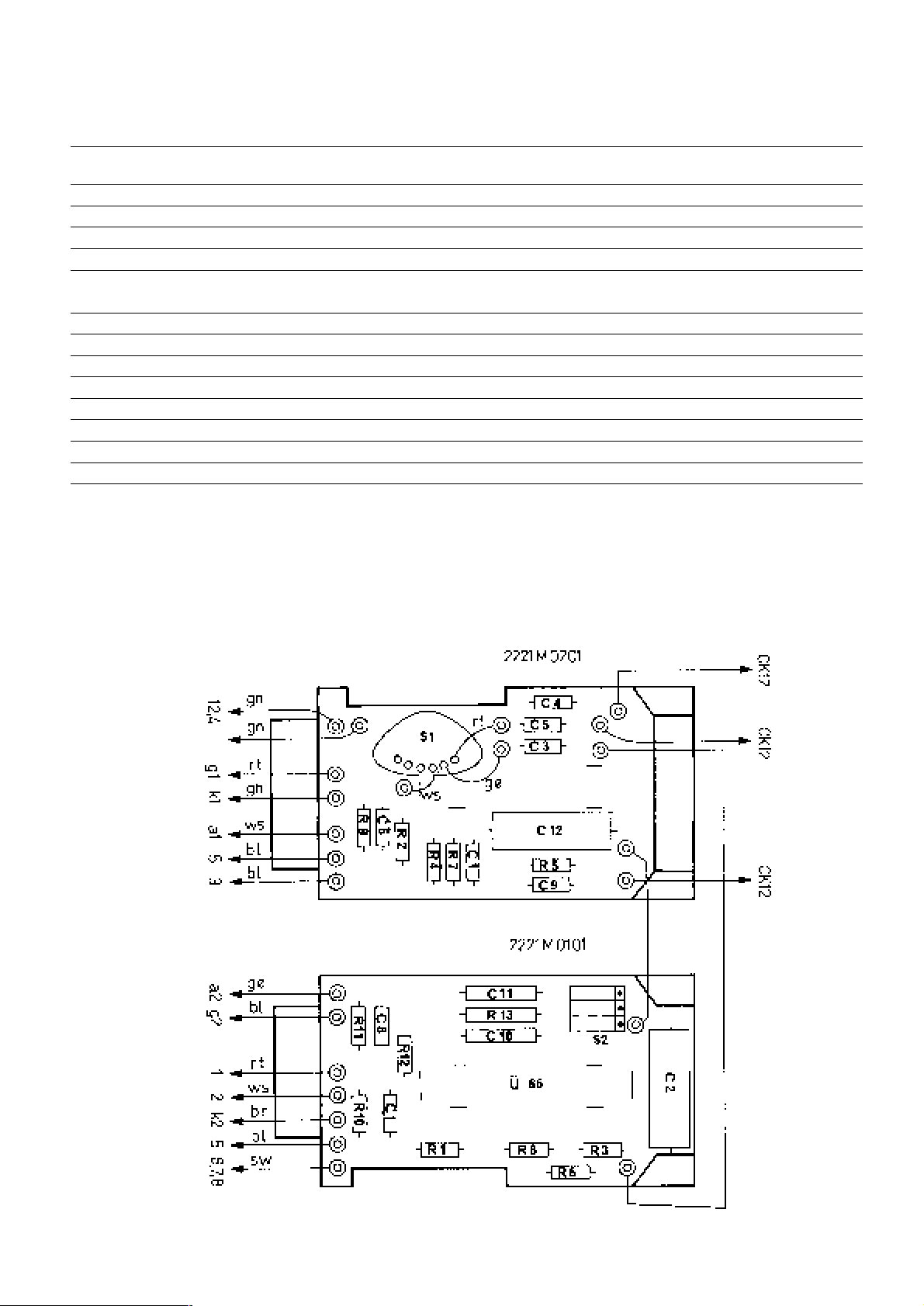
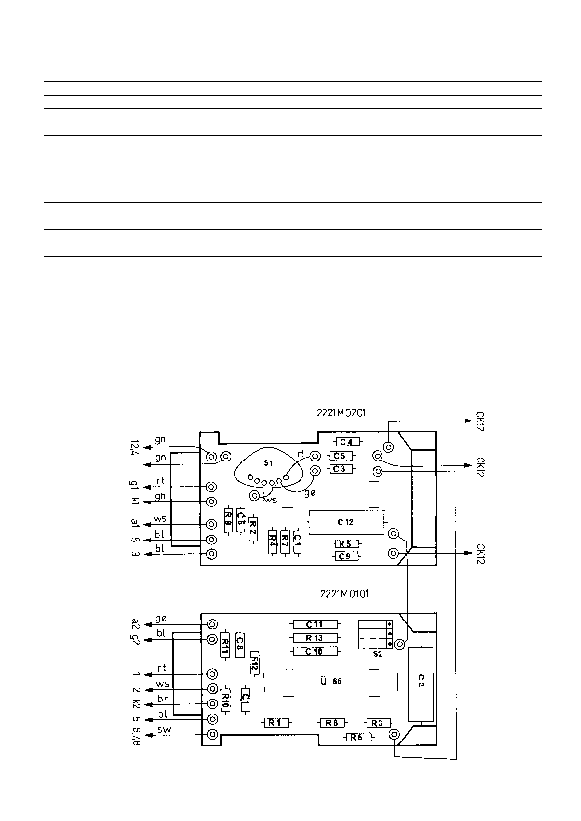
Bestückungsplan
Page 4
4
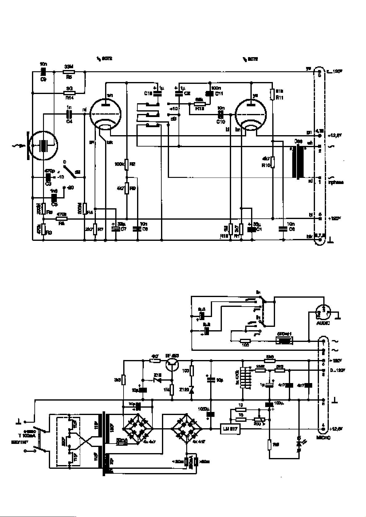
Schaltung des Netzgerätes
Schaltung des Mikrofons
Page 5

5
Mitgeliefertes Zubehör:
N 12 VR, Netzgerät
MK-Tube, 10 m Anschlußkabel
H15/T, Elastische Halterung
W42, Schaumstoffwindschutz
Stabiler Transportkoffer
Sind Sie an zusätzlichen Informationen über Mikrofone und ihre Anwendung interessiert, dann empfehlen wir Ihnen das Buch
„Mikrofontechnik“ von Norbert Pawera. Es ist im Verlag
„Arsis Baedeker und Lang Verlags GmbH“ erschienen und im
guten Musikfachhandel erhältlich.
Dabei werden Studio- und Bühnenanwendung gleichermaßen
berücksichtigt.
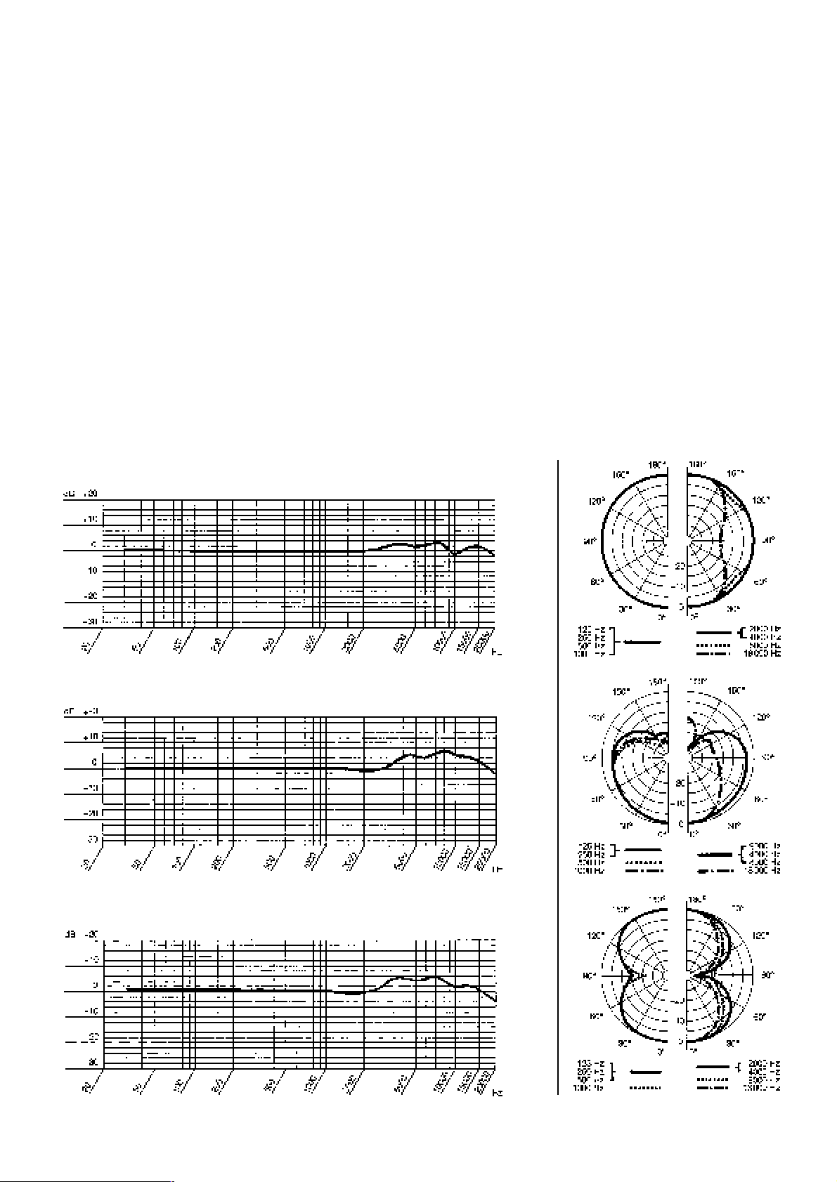
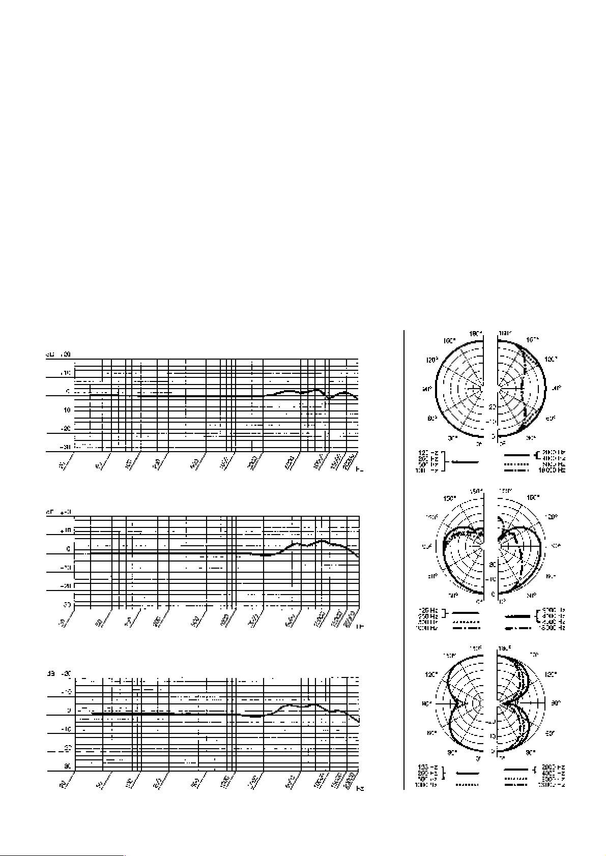
Frequenzkurven Polardiagramme
Niere
Achter
Ersatzteile
Bezeichnung
Print 1 Kplt.
Print 2 Kplt.
Hüllrohr
Hüllrohrschraube
Gitterkappe
Elektronenröhre # 6072
Röhrensockel
Gummilagerung
Kapsel CK 12
Sicherung 50 mA
Sicherung 250 mA
Bestellnummer
2221 M 0101
2221 M 0201
2221 M 0301
2221 Z 1101
2221 M 0401
2221 Z 2001
0013 E 0001
2221 Z 0601
2072 Z 0008
0012 E 0009
0012 E 0007
Bitte bestellen Sie Ersatzteile bei Ihrer lokalen AKG-Servicestelle oder AKG-Vertretung.
Kugel
Page 6

6
1. The Microphone
This microphone has been recreated to meet the demand for the
“tube sound“ with the design approach of today using modern
componentry around the “heart“ of the microphone – the original, specially selected 6072 tube. It should be stressed at this
point, that vacuum tubes with their heater filaments are much
more delicate than solid-state components. Consequently, the
user has to take great care in handling the microphone. Drops
from even moderate heights may cause the filament to break
and would result in immediate failure of the microphone.
It would be advisable for the users to keep a spare tube – specially selected by an AKG Service Departement – always ready for replacement.
How to replace the vacuum tube?
Turn the three grub screws at the lower end of the microphone
into the body in clockwise direction until the outer housing can
be pulled off in downwards direction.
The vacuum tube can now be removed by depressing the lower
(rubber) shockmount to free the tube with a foreward motion.
Taking the tube socket in one hand and the tube itself in the
other hand will enable you to separate the vacuum tube from
the socket. Insertion of a new tube should be done in reverse order of the description above.
How to change the sensitivity of the microphone?
The circuit design incorporates the facility to increase the nominal sensitivity of the microphone by 10 dB. This basic change
to the microphone’s data may be made by the user in the following manner:
1. Open the microphone according to the description in the last
paragraph.
2. On the top left corner of the transformer board are three
small p. c. board switches placed next to each other. Change all three switches to the opposite position with a small
object, like ball-pen or similar.
3. Close the microphone in reverse order of the opening procedure.
How to mount the microphone?
A special shock mount/stand adapter H 15/T is provided and
should always be used to mount the microphone on floor stands
or booms. The clamp of the shockmount should be guided from
the lower end of the microphone upwards until it is placed near
the gravitational centre (slightly below the engraving). The
shockmount can now be placed with the microphone on stands
or booms with thread sizes of 3/8 or 5/8 inch. It may also be
swivelled against the stand axis to suit the recording angle.
Powering of the microphone:
The required power unit N 12 VR is included in the delivery. It
is clearly marked and quite obvious by connector type and
size, how to connect the microphone to the power unit with the
10 m (30 ft.) multicore cable MK-Tube. The audio frequency
may be taken from the power unit transformer balanced by a
conventional audio cable with standard XLR-type connector.
Please see the circuit diagram for wiring details.
2. The Power Unit N 12 VR
This device not only supplies the microphone with the filament
and plate voltage for the vacuum tube, but facilitates also the
control of polar pattern and bass cut remotely from the micro-
phone. Prior to connecting the N 12 VR to AC power, check the
AC voltage of the power line you are going to connect the
N 12 VR to.
Check that the N 12 VR AC voitage selector to the right of the
power switch on the front panel is set to the same AC voltage.
If it is not, use a flat-blade screwdriver to set the AC voltage
selector to the correct voltage.
Warning: Connecting the N 12 VR to the wrong AC voltage
may destroy the unit and cause fire and/or electric shock.
Replacing Fuses
The fuse protecting the primary circuit is located in the
marked fuse compartment below the power connector.
Use a flat-blade screwdriver to open the fuse compartment lid.
Replace the fuse with a new fuse of the same type (T 100 mA)
and close the fuse compartment lid.
The 50-mA, fast-blow fuse protecting the anode circuit is
located on the circuit board inside the unit.
Disconnect the unit from AC power by unplugging
the power cable.
Remove the four screws fastening the top panel.
Remove the top panel.
Replace the fuse with a new 50-mA, fast-blow fuse.
Replace the top panel and fastening screws.
Power Connector
Especially on tour, you may need to connect the unit to a power
outlet that does not match the power connector on the supplied
power cable.
Purchase a matching power cable locaily that complies with IEC
and local safety standards and has a power connector with a
chassis ground pin. While in the same area, use this „local“
power cable only.
Should it be required to increase the connection between the
microphone and the power unit beyound 20 metres, an adaption within the power unit N-Tube becomes necessary.
According to the circuit diagram, a simple change of the fuse
link marked 250 mA from its fuse holder to the one next to it
marked > 20 m is all, which is required.
Page 7
7
3. Specifications of the Microphone
Operating Principle: Pressure gradient transducer with double-diaphragm and vacuum tube preamplifier
Directional Characteristics: Omni-, cardioid-, figure-eight, and six intermediate positions remotely controlled from the
microphone on the powering unit
Sensitivity at 1000 Hz: 10mV/Pa Ⳏ –40 dBV*)
Frequency Range: 30 to 20,000 Hz ± 2.5 dB from published curve
Electrical Impedance: 200 ohms ± 25 %
Recommended Load Impedance: 1000 ohms
Equivalent Noise Level: 32 dB (DIN 45405/CCIR 468-2)
22 dB-A (acc. to DIN 45412, A weighted)
Powering: Via the included powering unit N 12 VR with 115/230 VAC
Maximum Sound Pressure Level: For k=3 %=128 dB SPL Ⳏ 50 Pa
Pre-attenuation: Switchable to –10 dB and –20 dB
Roll-off Filter: Two position filter, remotely controllable from powering unit N-Tube
Connector: Large-sized Tuchel, 12 pin
Dimensions: 42 ø × 225 mm (1.65 ø × 8.9 inch)
Net Weight: 680 g (24 oz.)
Shipping Weight: Approx. 4.5 kg (~10 Ibs.)
*) The sensitivity may be increased by 10 dB with a switch on the p. c. board.
This product conforms to EN 50 082-1 and EN 50 081-1.
Component locations
Page 8

8
Circuit Diagram of the Microphone
Circuit Diagram of the N 12 VR
Page 9
9
Included Accessories:
N 12 VR, powering unit
MK-Tube, 10 m (30 ft) connection cable
H 15/T, elastic suspension
W 42, foam-type windscreen
Heavy-duty flight case
If you want to learn more about microphones and their applications, get a copy of “Microphones: technique & tech-
nology“ by Norbert Pawera. The book is published by “Arsis
Baedeker und Land Verlags GmbH“ and available at your local
music shop. Both studio and “onstage“ applications are discussed in detail.
Spare Parts
Description
pcb 1 compl.
pcb 2 compl.
housing
screw for housing
grid cap
# 6072 vacuum tube
tube socket
rubber support
capsule CK 12
fuse 50 mA
fuse 250 mA
Ordering code
2221 M 0101
2221 M 0201
2221 M 0301
2221 Z 1101
2221 M 0401
2221 Z 2001
0013 E 0001
2221 Z 0601
2072 Z 0008
0012 E 0009
0012 E 0007
Spare parts should be ordered at your local AKG Service Agent
or representative.
Frequency Response Polar Response
Cardioide
Figure-of-eight
Omnidirectional
Page 10

1. Le Microphone
Vu la grande demande pour le son dit de “tube“ nous avons remanié ce microphone selon l’état actuel de la technique. De modernes et fiables éléments ont été regroupés autour du “coeur“
du microphone – à savoir le tube 6072 original et spécialement
choisi à cet effet.
Dans ce contexte il ne faut pas oublier que le tube électronique
muni d’un élément de chauffage est beaucoup plus sensible que
la technique des transistors. Pour cette raison il faut utiliser ce
microphone avec soin et précaution. Même le choc produit par
une chute de petite hauteur peut causer la rupture du filament et
par là la défaillance totale du microphone.
Voilà pourquoi il est conseillé de tenir en réserve un tube choisi
par un poste de service aprés-vente AKG.
Comment remplacer le tube électronique?
Tournez les trois vis visibles sur l’extrémité inférieure du boitier
dans le sens des aiguilles d’une montre en les insérant dans le
corps du microphone jusqu’à ce que le boitier s’enlève facilement vers le bas.
Vous pouvez maintenant enlever le tube en serrant le bas de la
suspension élastique (partie en caoutchouc) à tel point que le
tube se dégage avec un mouvement en avant. Prenez ensuite le
culot d’une main et le tube de l’autre et séparez ainsi l’un de
l’autre.
Pour placer le nouveau tube procédez dans le sens inverse de
ladite description.
Comment augmenter la sensibilité du microphone?
Le branchement électrique du microphone permet d’augmenter
la sensibilité normale de 10 dB. Cela se fait comme suit:
1. Ouvrir le microphone selon la description donnée ci-dessus.
2. Sur le bord supérieur de gauche du transformateur imprimé
se trouvent trois petits commutateurs imprimés posés l’un à
côté de l’autre. Tournez tous les trois commutateurs à
l’aide d’un objet pointu (stylo à bille p. ex.).
3. Fermez le microphone dans le sens inverse de l’ouverture.
Comment se fait le montage du microphone?
Une suspension élastique spéciale/fixation pour pied de micro
H 15/T est incluse dans la livraison dont l’usage régulier est indiqué pour relier le microphone à un pied de sol ou une perche. Faites glisser la bride de la suspension d’en bas sur le
micro jusqu’au centre de gravité (un peu en dessous de la gravure). Ensuite vous pouvez visser la suspension sur des pieds ou
des perches munis d’un filet normalisé de 3/8 ou 5/8 pouces.
Il est également possible de pivoter la suspension sur l’axe du
pied ce qui permet d’orienter le microphone de façon optimale
pour la prise de son.
Alimentation du microphone:
Le bloc-secteur nécessaire à l’alimentation (“N 12 VR“) est inclus dans la livraison. Les divers types des fiches et les répères
facilitent le branchement correcte du microphone au bloc-secteur. Le câble multipolaire MK-Tube de 10 m de long sert à cet
effet. On peut également capter la basse fréquence du bloc-secteur (entrées symétriques) moyennant une fiche XLR-3. Pour ce
qui est du branchement des fiches voir le schéma de montage.
2. Le Bloc-secteur N 12 VR
Le bloc-secteur ne sert pas seulement à alimenter le tube électronique en tension de chauffage et en tension d’anodes, mais
il comprend également le dispositif de télécommande de la directivité et de l’atténuation des basses du microphone.
Avant la mise en service du bloc secteur N 12 VR, vérifiez si la
valeur sur laquelle est réglé le sélecteur de tension de l’appareil
(sur l’avant à droite, à côté de l’interrupteur marche/arrêt) est
bien identique avec la tension du secteur. Si ce n’est pas le cas,
il est facile de modifier le réglage du sélecteur de tension en utilisant un tournevis plat.
Le fusible sur le circuit primaire se trouve dans la partie inférieure de la prise secteur, dans un compartiment portant un
repère. On peut ouvrir ce compartiment à l’aide d’un tournevis
plat pour remplacer le fusible. On remettra toujours un fusible
de même valeur (T 100 mA).
Un second fusible (50 mA, a. i.), pour le circuit d’alimentation
en courant anodique, se trouve sur la carte, à l’intérieur de l’appareil. Pour avoir accès au fusible, couper l’appareil de son alimentation en débranchant le câble secteur, dévisser les 4 vis et
enlever la partie supérieure du boîtier.
Si la prise secteur ne correspond pas au type normalement utilisé dans le pays, procurez-vous, sur place, un càble secteur répondant aux normes de sécurité internationales et muni d’une
prise avec mise à la terre de l’appareil.
Au cas où il serait nécessaire d’utiliser une liaison entre micro
et bloc-secteur qui exède 20 m de longueur, il faut adapter le
bloc-secteur de façon correspondante.
Conformément àu schéma de montage ci-joint il suffit de changer la place du fusible 250 mA y présent en le mettant dans la
fixation à côté (répère: > 20 m).
10
Page 11

3. Specifications du microphone
Principe de fonctionnement: microphone à gradient de pression et à double membrane comprenant un préamplificateur
à tubes
Directivité: omnipotentielle, cardioïde, bidirectionelle et six positions intermédiaires, réglable par
télécommande du bloc-secteur N 12 VR
Sensibilité à 1000 Hz: 10 mV/Pa Ⳏ –40 dBV*)
Réponse en fréquence: 30–20.000 Hz ± 2,5 dB de la courbe nominale
Impédance électrique: 200 ohms ± 25 %
Impédance de charge recommandée: 1000 ohms
Niveau de bruit équivalent: 32 dB (filtre DIN 45405/CCIR 468-2)
22 dB-A (selon DIN 45412-A)
Alimentation: moyennant le bloc-secteur N 12 VR inclus dans la livraison, sous 115/230 V CA
Niveau de pression sonore maximal
pour un taux de distorsion par
harmonique de 3 %: 50 Pa Ⳏ 128 dB SPL
Préatténuateur: réglable sur le microphone à –10 dB et –20 dB
Atténuateur des basses: deux paliers, réglable par télé-commande du bloc-secteur
Connecteur: grosse fiche Tuchel T 3617 à 12 pôles
Dimensions extérieurs: 42 ø × 225 mm
Poids, net: 680 g
Poids brut, y compris l’emballage: 4,5 kg
*) Il est possible d’augmenter la sensibilité nominale de 10 dB moyennant le commutateur qui se trouve sur le circuit imprimé du microphone.
Ce produit répond à la norme EN 50 082-1 et EN 50 081-1.
11
Plan de montage
Page 12

12
Branchement du microphone
Branchement du bloc-secteur
Page 13

Accessories inclus:
N 12 VR, bloc-secteur
MK-Tube, cordon de raccordement, 10 m
H 15/T, suspension élastique
W 42, bonnette anti-vent en mousse
coffre de transport robuste
Si vous désirez des informations supplémentaires concernant
les microphones et leur application, nous vous recommandons
le manuel “Technique et Technologie des Micros“ de
Norbert Pawera. Il est paru chef “Arsis Baedeker und Lang Verlags GmbH“ et il est en vente dans le commerce spécialisé dans
la musique.
Dans ce contexte l’auteur tient compte des applications en studio aussi bien que sur scène.
13
Courbes de réponse en fréquence Diagrammes polaires
Cardioïd
Bidirectionelle
Omnidirectionelle
Pièces de rechange
Désignation
circuit imprimé 1
circuit imprimé 2
boîtier
vis de boîtier
calotte treillisée
# 6072 tube électronique
culot de tube
support en caoutchouc
capsule CK 12
fusible 50 mA
fusible 250 mA
Numèro de référence
2221 M 0101
2221 M 0201
2221 M 0301
2221 Z 1101
2221 M 0401
2221 Z 2001
0013 E 0001
2221 Z 0601
2072 Z 0008
0012 E 0009
0012 E 0007
Veuillez commander les pièces de rechange au service aprèsvente ou chez le concessionaire AKG local.
Page 14

1. Il Microfono
Vista la grande richiesta per il suono così detto a tubo „tube
sound“, abbiamo rifatto questo microfono secondo lo stato attuate della tecnica. I moderni ed affidabili elementi costruttivi sono
stati raggruppati per formare il „cuore“ del microfono: l’originale tubo 6072 selezionato con un procedimento speciale.
A questo proposito è d’uopo menzionare che il tubo elettronico
munito di un elemento di riscaldamento è molto più sensibile
della tecnica di transistor.
Per questo motivo l’utente deve fare molta attenzione ed avere
molta cura nell’uso di questo microfono. Anche una caduta da
basse altezze può causare una rottura del filamento di riscaldamento e quindi portare ad un guasto del microfono stesso. Ecco perchè si consiglia di tenere un tubo di riserva, un tubo acquistato da un rivenditore AKG.
Come si sostituisce una tubo elettronico?
Girare le tre viti di bloccaggio visibili sull’estremità inferiore del
corpo in senso orarlo fino a che il corpo esterno non si libera
facilmente verso la parte inferiore. Potete ora rimuovere il tubo
elettronico, facendo pressione sulla sospesione elastica di gomma; a questo punto il tubo elettronico si muoverà in avanti. Separare poi il tubo dalla sua base, afferrandola con una mano
mentre con l’altra si tiene il tubo e infine tirare.
Per inserire il tubo nuovo, operare nell’ordine contrario di come ut supra descritto.
Come si può aumentare la sensibilità del
microfono?
Il circuito elettrico del microfono permette l’aumento della sensibilità nominale di 10 dB. Questo può essere ottenuto dall’utente operando come segue:
1. Aprire il microfono come nella descrizione ut supra.
2. Sul bordo superiore sinistro del trasformatore stampato si trovano tre piccoli commutatori stampati posti uno vicino
all’altro. Cambiare la posizione dei tre commutatori con
un oggetto a punta (per. es. con una penna).
3. Chiudere il microfono seguendo l’ordine contrario dell’apertura.
Come montare il microfono?
La fornitura comprende la speciale sospensione elastica/collegamento per asta H 15/T che dovrebbe essere sempre usata
per collegare il microfono con il supporto o con il braccio. Far
scorrere il microfono sulla forcella dalla parte inferiore in su fino a che non raggiunge il centro di gravità (all’incirca appena
sotto l’incisione). Dopo di che la sospensione elastica può essere fissata sull’asta o sul braccio con lo standard 3/8 o 5/8
di pollice. Contemporaneamente è possibile muovere il microfono sull’asta, per permettere di orientarlo a piacere ottimizzando così la registrazione.
Alimentazione del microfono:
L’apparecchio necessario all’alimentazione („N 12 VR“)’ è incluso nella fornitura. Il collegamento del microfono all’apparecchio di alimentazione è facilmente riconoscibile dalle demarcazioni e dai tipi di spine ed è costituito da un cavo multipolare MK-Tube lungo 10 m. Con l’apparecchio di alimentazione si possono ugualmente captare le basse frequenze simmetricamente per mezzo di un collegamento XLR-3. Il collegamento dei fili della spina può essere visto dal diagramma del
circuito.
2. L’apparecchio di Alimentazione
L’apparecchio di alimentazione alimenta i tubi elettronici non
solo con tensione di calore e di anodi ma contiene anche il dispositivo di telecomando per la direttività e per l’attenuazione
del basso.
Prima di mettere in esercizio l’alimentatore, verificate per favore la tensione di rete del rispettivo paese paragonandola con
il valore preregolato sul selettore di tensione dell’alimentatore
(a destra, sul lato anteriore, accanto all’interruttore di rete). Se
è necessario commutare la tensione d’esercizio preregolata, si
può farlo molto semplicemente con un cacciavite piatto.
Il fusibile inserito nel circuito primario si trova nella parte inferiore della presa di rete in un comparto contrassegnato. Questo comparto può venir aperto, se necessario, con un cacciavite piatto, per sostituire il fusibile con uno dello stesso valore
(T 100 mA).
Un secondo fusibile (F 50 mA) che protegge il circuito di alimentazione anodica si trova sulla piastra all’interno dell’alimentatore. Dopo aver staccato l’alimentatore dalla rete, tirando il cavo di rete, e dopo aver allentato 4 viti, la parte superiore della scatola può venir tolta per poter accedere a questo fusibile.
Se nel paese, in cui l’alimentatore deve venir usato, si usa un
altro tipo di spina, dovete acquistare e usare un cavo di rete
che corrisponde alle norme di sicurezza internazionali e che è
dotato di una spina con massa.
Qualora dovesse essere necessario allungare il collegamento
tra il microfono e l’attacco a rete per più di 20 m, ci sarà bisogno di una piccola modifica nell’alimentazione.
Conformemente allo schema di montaggio accluso basterà eseguire un semplice spostamento del fusibile presente a 250 mA
nell’ubicazione vicina, contrassegnata > 20 m.
14
Page 15

15
Piano di montaggio
3. Dati tecnici del microfono
modo di funzionamento: microfono a gradiente di pressione e a doppila membrana comprendente un preamplifica-
tore
direttività: omnidirezionale, cardioide, bidirezionale e sei posizioni intermedie, regolabili tramite
telecomando dall’apparecchio di alimentazione rete N 12 VR
sensibilità a 1000 Hz: 10 mV/Pa Ⳏ –40 dBV*)
risposta in frequenza: 30–20.000 Hz ± 2,5 dB dalla curva nominale
impedenza elettrica: 200 Ohm ± 25 %
impedenza di carico raccomandata: 1000 Ohm
livello di rumore equivalente: 32 dB (filtro DIN 45405/CCIR 468-2)
22 dB-A (in conformità alla DIN 45412-A)
alimentazione: l’adattatore alimentazione a rete N 12 VR a 115/230 VAC incluso nella fornitura
pressione acustica limite
per fattore di distorsione 3 %: 50 Pa Ⳏ 128 dB SPL
preattenuazione: regolabile al microfono a –10 dB e –20 dB
preattenuatore del basso: due posizioni, teleregolabili dall’apparecchio alimentazione rete
collegamento spina: spina grossa Tuchel T 3617 a 12 poli
dimensioni esterne: 42 ø × 225 mm
peso netto: 680 g
peso lordo: 4,5 kg
*) La sensibilità nominale può essere aumentata di 10 dB per mezzo di tre commutatori sul circuito stampato.
Questo prodotto risulta conforme alla norma EN 50 082-1 e EN 50 081-1.
Page 16

Diagramma del circuito dell’apparecchio di alimentazione
16
Circuito interno del microfono
Page 17

Pezzi di ricambio
descrizione
circuito stampato 1
circuito stampato 2
corpo
viti del corpo
cappuccio del reticolo
tubo elettronico #6072
base del tubo
sostegno di caucciù
capsula CK 12
fusibile 50 mA
fusibile 250 mA
17
numero di riferimento
2221 M 0101
2221 M 0201
2221 M 0301
2221 Z 1101
2221 M 0401
2221 Z 2001
0013 E 0001
2221 Z 0601
2072 Z 0008
0012 E 0009
0012 E 0007
Raccomandiamo di ordinare i pezzi di ricambio dal Vostro rivenditore AKG o da un concessionario AKG.
Accessori inclusi
N 12 VR – apparecchio alimentazione a rete
MK-Tube, 10 m cavo di collegamento
H 15/T, base elastica
W 42, gomma piuma anti soffio
valigetta di trasporto robusta
Curva di risposta in frequenza Diagrammi polari
Cardioide
Bidirezionale
Omnidirezionale
Page 18

1. El micrófono
La gran demanda por el llamado “sonido tubo“ dio origen a
una nueva concepción de este micrófono según los conocimientos más recientes de la técnica de construcción. Elementos
modernos y fiables han sido agrupados alrededor del “corazón“ del micrófono – el tubo 6072 original y especialmente seleccionado a ese fin.
Cabe señalar en este contexto que el tubo electrónico con el
elemento de calefacción incorporado es mucho más sensible
que la técnica de transistores, por lo que se requiere mucho cuidado y precaución al utilizar el micrófono. Incluso los golpes
provocados por una caída desde poca altura ya pueden causar la rotura del filamento calefactor, teniendo como consecuencia el fallo completo del micrófono. Se recomienda, por lo
tanto, tener en reserva un tubo de recambio seleccionado por
una agencia de servicio de AKG.
¿Cómo se recambia el tubo electrónico?
Los tres pasadores roscados visibles en el extremo inferior de la
caja se enroscan en el sentido de las agujas del reloj en el
cuerpo del micrófono, hasta que se consiga fácilmente retirar
la caja hacia abajo. Ahora puede sacarse el tubo electrónico,
aplastando la parte inferior de la suspensión elástica (el elemento de goma), hasta que el tubo se desprenda mediante un
movimiento hacia adelante. Sujetar el zócalo del tubo con una
mano y el tubo con la otra y luego separarlos. El montaje de un
tubo nuevo se efectúa en el sentido contrario de lo arriba indicado.
¿Cómo se puede aumentar la sensibilidad del
micrófono?
Gracias al circuito eléctrico del micrófono se puede incrementar la sensibilidad nominal en 10 dB. Para ello hay que proceder de la manera siguiente:
1. Abrir el micrófono tal como ha sido descrito anteriormente.
2. En el borde izquierdo superior del transformador del circuito impreso se encuentran tres pequeños conmutadores uno
al lado del otro. Conmutar cada uno de los tres mediante
un objeto agudo (un bulígrafo p. ej.).
3. Cerrar el micrófono en el sentido contrario del que se abrió.
¿Cómo se hace el montaje des micrófono?
Está incluido en el volumen de suministros una suspensión elástica/adaptador de soporte H 15/T que se debe utilizar, siempre que el micrófono se une mecánicamente al soporte o a la
jirafa. Mover la abrazadera de la suspensión desde abajo hacia el centro de gravedad del micrófono (un poco debajo de la
grabadura). Luego se puede atornillar la suspensión en soportes o jirafas con un estándard de 3/8“ o 5/8“. También es posible hacer girar la suspensión frente al eje des soporte, para
que el posicionamiento del micrófono sea optimal para la grabación.
La alimentación del micrófono:
El alimentador “N 12 VR“ necesario para la alimentación está
incluido en el volumen de suministros. Por las distintas conexiones y marcaciones se reconoce fácilmente, cómo el micrófono tiene que ser conectado al bloque de alimentación. Para
ello sirve el cable multipolar MK-Tube de 10 m de longitud. Asimismo, se puede recoger la BF en el bloque de alimentación
(entrada balanceada) mediante un conector XLR-3; cuanto al
cableado de los conectores véase el esquema eléctrico.
2. El bloque de alimentación N 12 VR
El bloque de alimentación no asegura tan sólo la tensión de filamento y la tensión anódica para el tubo electrónico, sino que
contiene también el telecontrol de la característica direccional
y de la atenuación de bajos del micrófono.
Antes de poner en funcionamiento el alimentador de red es necesario informarse acerca de la tensión de red local y compararla con el valor ajustado en el selector de tensión del aparato
(adelante a la derecha al lado del conmutador de alimentación.) Si es necesario hacer una conmutación de la tensión de
alimentación, puede realizarse fácilmente con un desatornillador plano.
El fusible insertado en el circuito primario se encuentra en la
parte interior del borne de la red en un compartimiento marcado. Este puede abrirse con un desatornillador plano y el fusible
se puede cambiar por otra del mismo tipo (T 100 mA).
Un segundo fusible (50 mA, de acción rápida), que protege el
circuito alimentador para la alimentación de tensión anódica
se encuentra en la platina en el interior del aparato. Luego de
desenchufar el cable del alimentador de red y de soltar 4 tornillos se puede quitar la parte superior de la caja, obteniendo
así acceso al fusible.
Si en el país en el que se quiere utilizar el aparato es corriente
emplear un enchufe de red diferente, habria que adquirir y utilizar en dicho país un cable que cumpla con las normas de seguridad internacionales y que disponga de un enchufe con puesta a tierra.
En el caso que se necesite una conexión de más de 20 m entre
el micrófono y el bloque de alimentación, se impone una readaptación en el bloque de alimentación. De acuerdo con el diseño de circuito incluido, ésta sólo consiste en sacar el fusible
250 mA y insertarlo en el portafusible adyacente (marcado
> 20m)
18
Page 19
19
Esquema de montaje
3. Datos técnicos del micrófono
Mode de funcionamiento: Micrófono de membrana doble y gradiente de presión con preamplificador de tubos
Característica direccional: Omnidireccional, cardioide, bidireccional y seis etapas intermedios seleccionables por
telecontrol en el bloque de alimentación N 12 VR
Sensibilidad con 1000 Hz: 10 mV/Pa Ⳏ –40 dBV*)
Campo de frecuencia: 30–20.000 Hz ± 2,5 dB de la curva fijada
Impedancia eléctrica: 200 Ohm ± 25 %
Impedancia de carga recomendada: 1000 Ohm
Nivel de ruido equivalente: 32 dB (filtro DIN 45405/CCIR 468-2)
Alimentación: Mediante el alimentador de red N 12 VR incluido en el volumen de suministros;
115/230 VCA
Presión sonora máx para 3% THD: 50 Pa Ⳏ 128 dB SPL
Preatenuación: En el micrófono regulable –10 dB y –20 dB
Atenuación de bajos: 2 intervalos, seleccionables mediante el telecontrol en el bloque de alimentación
Conexión: Gran conector Tuchel T 3617 de 12 polos
Dimensiones exteriores: 42 (diámetro) × 225 mm
Peso: 680 g neto
Peso bruto, embalaje incluido: 4,5 kg
*) Mediante el conmutador en el circuito impreso del micrófono se puede incrementar la sensibilidad nominal en 10 dB.
Este producto cumple con la norma EN 50 082-1 y EN 50 081-1.
Page 20

Diseño de circuito del micrófone
20
Diseño de circuito del bloque de alimentación
Page 21

Accesorios incluidos
N 12 VR, bloque de alimentación
MK-Tube, cable de conexión de 10 m
H 15/T, suspensión elástica
W 42 pantalla antiviento de goma-espuma
Maletín de transporte robusto
21
Piezas de recambio
Denominación
Conjunto del circuito impreso 1 completo
Conjunto del circuito impreso 2 completo
Tubo envolvente
Tornillo del tubo envolvente
Casquillo de malla metálica
Tubo electrónico 6072
Zócalo de tubos
Suspensión elástica
Cápsula CK 12
Fusible 50 mA
Fusible 250 mA
Número de pedido
2221 M 0101
2221 M 0201
2221 M 0301
2221 Z 1101
2221 M 0401
2221 Z 2001
0013 E 0001
2221 Z 0601
2072 Z 0008
0012 E 0009
0012 E 0007
Para encargos de piezas de recambio diríjase a su agencia de
servicio o representación local de AKG.
Curvas de frecuencia: Diagramas polares
Cardioide
Bidireccional
Omnidireccional
Page 22

1. O Microfone
Este microfone foi recriado para cumprir as exigências de mercado por um “som de válvula“ com o design dirigido ao uso do
componente moderno de hoje em dia em volta do “coração“
do microfone – a original e especialmente selecionada válvula
6072. Uma coisa tem quer reforçada aqui, as válvulas á vácuo
com seus filamentos de aquecimento são muito mais delicadas
do componente de solid-state. Consequentemente, o usuário
tem que ter um grande cuidado no manuseio do microfone. Até
mesmo quedas de alturas moderadas poderia quebrar os filamentos e iria resultar em uma falha imediata do microfone. Seria aconselhável aos usuários ter uma válvula sobresalente –
pronta para ser substituída.
Como substituir a válvula?
Gire os três parafusos na parte inferior do corpo do microfone
em sentido horário até a carcaça poder ser puxada para
baixo. A válvula agora pode ser removida apertando-se a suspensão elástica (borracha) para liberar a válvula com um movimento para baixo. Separe a válvula do soquete segurando-a
com uma das mãos e com a outra liberando-a do soquete. A
coloção de uma nova válvula deverá ser feita na ordem inversa da descirção acima.
Como mudar a sensibilidade do microfone?
O design do circuito incorpora a facilidade de aumentar a sensibilidade nominal do microfone em 10 dB. Esta troca básica
nos dados do microfone pode ser feita pelo usuário da seguinte maneira:
1. Abra o microfone de acordo com a descrição acima.
2. Na parte superior esquerda da placa do transformador existem três pequenas chaves p.c. na placa posicionadas próximas umas das outras. Mude todas as três chaves para a posição oposta com uma chave de fenda ou similar.
3. Feche o microfone na ordem inversa do procedimento de
abertura.
Como montar o microfone?
Uma suspensão elástica/adaptador de tripé H 15/T especial é
fornecido e deverá sempre ser usado para montar o microfone
em tripés de chão ou booms. O apoiador da suspensão elástica deverá ser guiado da parte inferior do microfone para cima
até ele ser posicionado próximo ao centro gravitacional (um
pouco abaixo do logotipo). A suspensão elástica pode agora
ser colocada com o microfone na estante ou booms com roscas
de 3/8“ ou 5/8“. Ela poderá também ser girada contra o eixo
do tripé para se adaptar ao ângulo de gravação.
Alimentação do microfone:
A unidade de alimentação N 12 VR está marcada de forma bastante clara e óbvia pelo tipo de conector e tamanho, como se
deve conectar o microfone a unidade dealimentação com o cabo multicor de 10 m MK-Tube. A frequência de àudio pode ser
levada do transformador da unidade de alimentação balanceado por um cabo de áudio convencional com um conector
padrão do tipo XLR. Por favor veja o diagrama do circuito para detalhes de ligação.
2. A unidade de alimentação N 12 VR
Este sistema não apenas alimenta o microfone com voltagem
para o filamento e placas da válvula, mas facilita também remotamente o controle do padrão polar e corte de graves do
microfone, antes de conectar o N 12 VR na corrente de AC, verifique a voltagem da corrente onde você vai conectar o N 12
VR. Verifique se o seletor de voltagem AC do N 12 VR à direita
da chave liga/desliga no painel frontal está ajustada para a
mesma voltagem de AC. Se não, use chave de fenda para ajustar o seletor de voltagem para a voltagem correta.
Cuidado: Conectar o N 12 VR na voltagem de AC errada poderá destruir a unidade e provocar fogo e/ou choque elétrico.
Trocando os Fusíveis
O fusível que protege o circuito primário está localizado no
compartimento impresso fuse em baixo do conector de força.
Use uma chave de fenda para abrir a tampa do compartimento do fusível. Troque o fusível por um novo do mesmo tipo
(T 100 mA) e feche a tampa do compartimento do fusível. O
fusível de 50 mA que protege o circuito anodo está localizado na placa do circuito dentro da unidade.
Desconecte a unidade da linha de AC desplugando o
cabo de força.
Remova os quatro parafusos que prendem o painel superior.
Remova o painel superior.
Troque o fusível por um novo de 50 mA.
Recoloque a painel superior e prenda com os parafusos.
Conector de Força
Especialmente em viagens, você pode precisar conectar a
unidade à uma tomada de força que não combina com o
conector do cabo de força. Compre um cabo de força que sirva na tomada e que cumpra com o padrão IEC e de segurança
local e possua um conector de força com um pino terra no chassi. Enquanto estiver na mesma àrea, utilize apenas este cabo
de força “local“. Ele deverá ser requerido para aumentar a conexão entre o microfone e a unidade de força além de 20 metros, uma adaptação dentro da unidade de força N-Tube se torna necessário. De acordo com o diagrama do circuito, uma
simples mudança na conexão do fusível marcada 250 mA do
seu apoiador para aquele próximo a ele marcado > 20 m é tudo, o qual é o exigido.
22
Page 23

23
3. Especificações do Microfone
Princípio de Operação: Transdutor de gradiente de pressão com diafragma duplo e pré-amplificador à válvula
Características Direcionais: Omni-, cardióide-, figura-oito, e seis posições intermediárias remotamente controladas do
microfone na unidade de alimentação
Sensibilidade à 1 kHz: 10 mV/Pa –40 dBV*)
Região de Frequência: 30 à 20.000 Hz ± 2,5 dB desde a curva publicada
Impedância Elétrica: 200 ohms ± 25 %
Impedância de Carga Recomendade: 1000 ohms
Nível de Ruído Equivalente: 32 dB (DIN 45405/CCIR 468-2):
22dB-A (de acordo com DIN 45412, A-ponderado)
Alimentação: Através da unidade de alimentação inclusa N 12 VR com 115/230 VAC
Máximo Nível de Pressão Sonora: para k=3 % =128 dB SPL 50 Pa
Pré-atenuação: Chaveáve para –10 dB e –20 dB
Filtro de Corte de Graves: Filtro de duas posições, controlado remotamente da unidade de alimentação N-Tube
Conector: Tuchel tamanho grande de 12 pinos
Dimensões: 42 ø × 225 mm
Peso líquido: 680 g
Peso de transporte: Aproximadamente 4,5 kg
*) A sensibilidade pode ser aumentada em 10 dB com uma chave na placa p.c..
Este produto esta em conformidade com EN 50 082-1 é na EN 50 081-1.
Localização do Componentes
Page 24

24
Diagrama do Circuito do Microfone
Diagrama do Circuito do N 12 VR
Page 25
25
Frequência de Resposta
Resposta Polar
Cardióide
Figura-de-oito
Omnidirecional
Acessórios Incluídos:
N 12 VR, unidade de alimentação
MK-Tube, cabo de conexão de 10 m
H 15/T, suspensão elástica
W 42, paravento tipo espuma
Estojo
Se você quiser aprender mais sobre microfones leia “Micro-
phones: technique & technology“ de Norbert Pawera.
O livro é publicado por “Arsis Baedeker und Land Verlags
GmbH“. Ambas aplicações em estúdio e palco são discutidas
com detalhes.
Peças de Reposição
Descrição
pcb 1 compl.
pcb 2 compl.
caraça
parafusos para a carcaça
grade
válvula # 6072
soquete da válvula
suporte de borracha
cápsula CK 12
fusível 50 mA
fusível 250 mA
Código do pedido
2221 M 0101
2221 M 0201
2221 M 0301
2221 Z 1101
2221 M 0401
2221 Z 2001
0013 E 0001
2221 Z 0601
2072 Z 0008
0012 E 0009
0012 E 0007
As peças de reposição deverão ser encomendadas com o seu
representante AKG da sua cidade.
Page 26

Notizen - Notes - Notes - Notizie - Notas - Notas
Page 27

Notizen - Notes - Notes - Notizie - Notas - Notas
Page 28

Technische Änderungen vorbehalten. Specifications subject to change without notice. Ces caractéristiques sont susceptibles de modifications.
Ci riserviamo il diritto di effettuare modifiche tecniche. Nos reservamos el derecho de introducir modificaciones técnicas. Especificações sujeitas à mudanças sem aviso prévio.
Mikrofone · Kopfhörer · Drahtlosmikrofone · Drahtloskopfhörer · Kopfsprechgarnituren · Akustische Komponenten
Microphones · Headphones · Wireless Microphones · Wireless Headphones · Headsets · Electroacoustical Components
Microphones · Casques HiFi · Microphones sans fil · Casques sans fil · Micros-casques · Composants acoustiques
Microfoni · Cuffie HiFi · Microfoni senza filo · Cuffie senza filo · Cuffie-microfono · Componenti acustici
Micrófonos · Auriculares · Micrófonos inalámbricos · Auriculares inalámbricos · Auriculares con micrófono · Componentes acústicos
Microfones · Fones de ouvido · Microfones s/fios · Fones de ouvido s/fios · Microfones de cabeça · Componentes acústicos
Printed in Austria on recycled paper. 03/00/9100 U 0906
AKG Acoustics GmbH
Lemböckgasse 21–25, P.O.B. 158, A-1230 Vienna/AUSTRIA
Tel: (43 1) 86 654-0*, Fax: (43 1) 86 654-516
http://www.akg-acoustics.com, e-mail: sales@akg-acoustics.com
AKG Acoustics, Harman Pro GmbH
Bodenseestraße 228, D-81243 München/GERMANY
Tel: (089) 87 16-0, Fax: (089) 87 16-200
http://www.akg-acoustics.de, e-mail: info@akg-acoustics.de
AKG ACOUSTICS, U.S.
1449 Donelson Pike, Nashville, TN 37217, U.S.A.
Tel: (615) 360-0499, Fax: (615) 360-0275
Arbiter Pro Audio
Wilberforce Road, London NW9 6AX/ENGLAND
Tel: (0181) 202 1199, Fax: (0181) 202 7076
Studer Japan Ltd.
2-43-7, Uehara, Shibuya-ku, Tokyo 151-0064/JAPAN
Tel: (813) 3465-2211, Fax: (813) 3465-2214
Erikson Pro Audio
620 McCaffrey, St-Laurent, Quebec, H4T 1N1, CANADA
Tel: (514) 738-3000, Fax: (514) 737-5069
Internet: www.jam-ind.com/eriksonpro
 Loading...