

Page 1
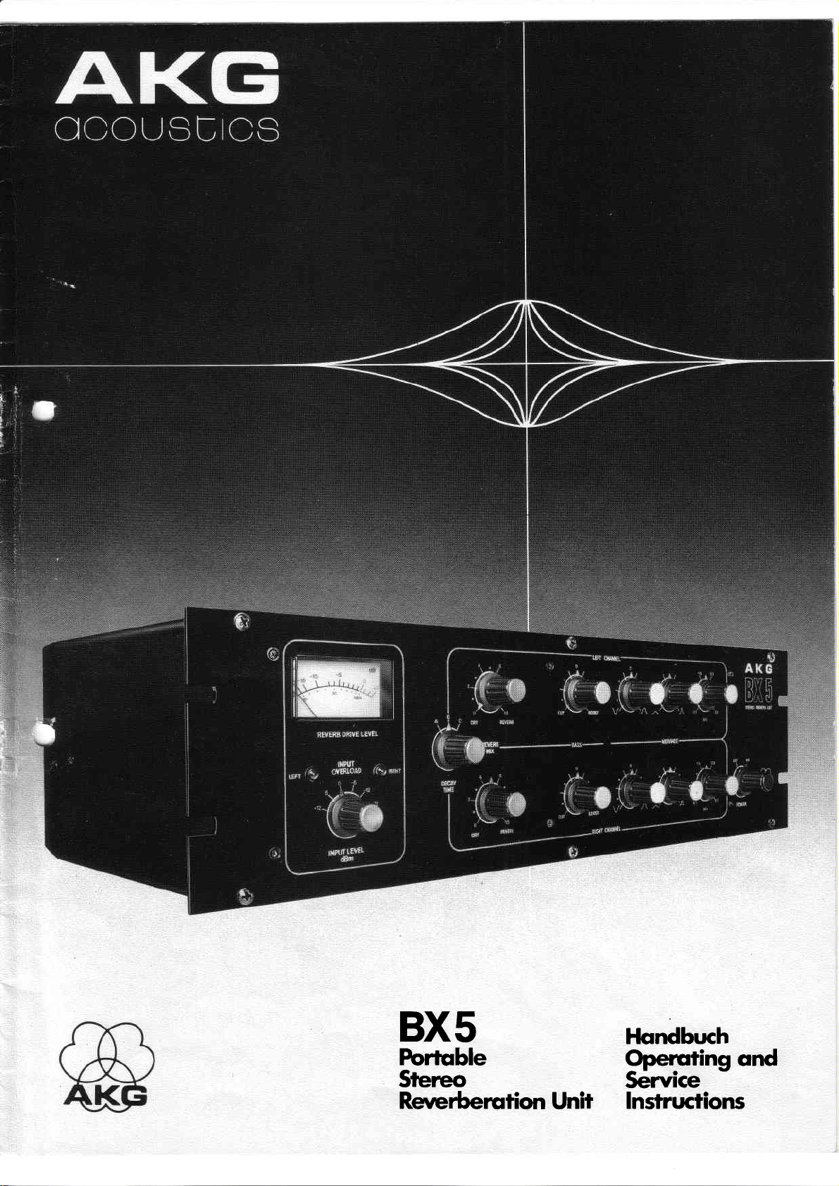
BX5
Forlqble
Srereo
Rererberution
Unir
Flondbuch
Opercring ond
)ervlce
Insfructions
Page 2
INHALT:
I
Technische Beschreibung
.
CO NTE NTS:
I . Generol Description
TF
'
a
2. Technische
Betriebshinweise
3.
lnbetriebnohme
3.1.
3.2. Anschlusse
Einpegelung
3.3.
\..
3.4. Ansch
Bedienungselemente
3.5.
4. Scho
5.
ltungsbeschreibung
Reporofuronleifung
6. Scholtungen
Dofen
Iußmöglichkeifen
2.
Specificotions
3.
Operoting Instr.uctions
3.1 . Setup procedure
3.2 . Connections
3.3.
Level
3.4. How
odiustment
to connect fo
equipment
3.5.
Controls
4.
Circuit
Repoir
5.
6.
Circuit diogi"oms
Description
Instructions
ossociofe
iL I
r-V
I
7. Bestückungsplöne
8. Srucklisre
Components
7.
8. Porfs
List
locotion
Page 3
TECHNISCHE
I .
BESCHREIBUNG
GENERAL
I .
DESCRIPTION
Dos
AKG BX 5 isf ein kleines, kompoktes Stereo-Nochhollgeröt,
ebenfolls dos
besitzt
BX l5
Dos
BX 5 beinholtet einen Hollkonol mif
Einvoll kompotibel zu onderen Geröten
studios zur Anwendung kommen.
Eine hohe Hollquolitat
erreichi, wobei
besonderen
die
meter
Unser
schließlich
Hollousgong
Um opiimole
Frequenzgong
Raumen
sfel Iungen vorhonden .
In
Aufnohmesfudios
keiten
roum
In Rundfunkstudios konn dos BX 5 unter onderem dozu
dem Signol
Stoiionen zu
können mitiels
spots erzielt werden.
Musiker
dernklong" onderer Hollgeröte kennen,
Dos BX 5 hot
röten
o Verwendung
o Hohe Eigenresoncnzdichte
o Hohe
wirkungsvol I nochzubi lden.
potentierte Torsionswellenleiter-Prinzip
gleichen
die
und BX l0 ouszeichnen und ist für einen Gestelleinbou konzipiert.
und Ausgönge
erreicht wurde.
potenfierfes Nochhollsystem ist Ubrigens dos
Hollröumen
gleichkommi.
vorfinden.
für
die vielfaltigen
zu besonders
und
BX 20,
wie
lmpulsdichte, um die
besonderen Klongeigenschoften
symmetrisch, wobei die
sind
durch dos von AKG poientierte TTL-System
wird
gleichmößige Ausklong
der
stotistischen
besiizt.
Hollquoliiat zu
über die Hollzeit, der noiürlichen
Es ist sicherlich
erhöhter
des BX 5 besondere Hervorhebungen
begeisterte
einige idente
BX 15 und BX l0:
des
Verönderungen der Feder und ihrer Poro-
-dos
keinen
gorontieren,
Diese Ausgewogenheii
dos BX 5 eine Vielzohl
wird
Anwendungen
"lvloduloiion"
storker
Loufheit
Torsionswellenleiter-Prinzips
und effektiver
Tonoufnohme-Enthusiosten,die
lvlerkmole
vielen Schqllreflexionen eines Roumes
Stereoein- und ousgöngen.
sind, die in
des Nochhollsignqls durch
trockenen
besii-zf
preisgünstig genug,
eingesetzt zu werden.
werden ongenehm überroscht
zu den
(TTL)
die die Geröte BX 20,
Pegel und lmpedonzen
Rundfunk
einzige
(unverhollten)
TTL-System
dos
Verhöltnissen von
ist bei ollen Hollzeitein-
Anwendungsmöglich-
von
um
verwendet werden,
zu verhelfen, wos bei AM-
Reichweiie
größeren
fi:hrt.
und Effekte fi.ir
den typischen
und teureren Ge-
(potentierf)
welches
verwendet.
Alle
und Aufnohme-
-
System
in
Anteil
einen
[edem
Auch
ein-
om
guten
Abhor-
Werbe-
"
Fe-
sein.
Es
The AKG BX 5 is o compoct Stereo
utilizing
(TTL).
in our BX 20, BX l5 ond BX l0 Reverberotions
compoctly designed in o
The
puis
donces
broodcosting ond
High
AKG Torsionol
reverberotion chorocteristics mode possible
springs whose tronsmission properties
by
Our
including live chombers
To mointoin
provides
Truly bolonced
time
In recording
os o
ploced
iioning to finol
In
increose overoge modulotion
It will olso provide
production
Musicions,
with the
find
for
The BX 5 hos
BX 20,
o
o High density
o
the potented Torsionol Tronsmission
lt possesses the exceptionol sound quolities inherent
rockmount
BX
5 is o single
ond oulpufs/ both being bolonced, ond levels
fully compotible
ore
reverberotion quoliiy
stotisticol voriotions of the
polenied
ormonce.
frequency-dependenf
o
setiing.
primory
in eoch control
broodcost
of commerciols.
performers
sound of
the
BX 5 on
surposses the
BX l5
Uses Torsionol Tronsmission
High
pulse
noturo I ly
trqnsmission
recording.
Tronsmission Line
reverb
system
. ..
optimol reverb
reverberotion is
studios, the BX
reverb source, yet
studios, it moy be
o number
ond
reverberont
room for opplicoiions
mostering.
enhoncemeni
ond recording-enthusiosts
"typicol"
offordoble oddition fo iheir
heretofore
sound
feotures
of
BX
l0 Reverberoiion
of
resononf frequencies
densify to duplicote
environments
Reverberotion
configurotion.
line system with stereo in-
those commonly
with
is ossured ihrough the potented
system,
spring
is fhe
only reverb
which does
quolity,
decoy-iime chorocterisfic.
obioinoble ot ony decoy-
5 will find brood opplicotion
is economicol
used wiih
Ievel or
ond speciol
spring reverberofion
ovoiloble
in common
Line
principle
the mony
Line principle
with
by
hove been
porometers,
device
not contoin
fl
the
TTL
system olso
enough
from mix oudi-
"live"
siotion " loudness"
effects in the
equipmenf
in this
wiih the AKG
Uniis:
(potented)
sound poihs
Unit
Units, but is
impe-
ond
used in
highly
smooth
o series of
controlled
utter-free
to
be
voice to
.
fomilior
units, will
which
price
ronge.
v
jr
of
o Hohe
o Lineorer
o Genoue Nochbildung
o Einstellbore
Eingebouter
o
Hollkonols
Eingeboute
o
verholltem Signol
o Besondere
borer
o Es
sind keine Adiustierungen
des Gerötes notwendig
2
stotistische Diffusiföf im
Frequenzverlouf
von okusi.
Eingongsempfindlichkeit
Limiter zur Vermeidung
Überblendung
Ruckkopplungssicherheit
N öhe
von lvlon itorloutspreche
von
Frequenz-
Poromefern
unverholltem zu
oder
und
Übersteuerungen
von
und domit
rn verwendbor
Arretierungen
Zeitbereich
notürlicher Räume
des
ousschließlich
sogor in
unmitlel-
für den Tronsport
o High
degree
time domoins
o Lineor frequency
cot
ions
Precise
o
Adiustoble
o
o Built-in
Built-in
o
qcoustic
o No
monitor
o No
speciol mounting
of siotisticol
duplicofion
input
limiter io
reverb/dry
feedbqck
loudspeokers
diffusion in both
response for moximum
of noturol room
sensitivity
prevenf
overdriving
signol mixing
... even when
or isoloiion
Teverberoiion
required
frequency
ronge
ofoppli-
of reverb
ploced
close to
for instollofion
ond
effects
inpur
Page 4
o Es ist keine
noiwendig
besondere Instolloiionsmoßnohme
für den Betrieb
des BX
5
o No
locking
or reodiustmenis
necessory
for tronsportotion
Periodische
o
Es finden
o
Zusötzliche Besonderheiten des BX
Eingebouter
o
o Eingebouter porometrischer Enizerrer
bereich
o 19." Einschubtechnik
o Gemeinsomer
o VU-lvleter Anzeige
beiden Eingongssignole
o Leuchtdiodenonzeige
\t
\t
Louflose Hollzeiieinstellung
o
o ldeol für den mobilen Einsotz
(5,5
o Hollsystem
gebout
2,
TECHNISCHE DATEN
Ho llzeif:
co. 1
Nomino ler Eingongspegel
-22, -12,
beide Konäle
Mqximoler
l8 dB
Limiier:
(wirkt
eingestel ltem
Bereich:
E
ingongsimpedonz:
l0
45
Ho
I Iobmischung:
Getrennt für
"trockenem"
Nomino
-22,
lieferten
Moximo ler
Angeschlossene
heii
tretenden
Ausgongs
3
Empfoh
lene
2
Frequenzgong
20
Wortung und Nochiustierungen
3-pol. Stondord
Tiefen-Regler, fi:r
(drei
Eingongspegel-Scholter für
Hollonsteuerung
der
on.
von
kg netto)
konn leichi ous
werden
und 3 Sek.
,2
:
-6,
+6
0,
und
eingestel lt),
Eingongspegel:
über
eingestelliem Nominolpegel
nur
ouf dos zu
co. l8 dB
kOhm,
symmetrisch
kOhm,
symmetrisch
ler Ausgongspegel:
+6
0 und
Zusfond
Ausgongspegel
von
wenigstens
Signolspiizen
impedonz:
200
Ohm, trofosymm.
Losf impedonz:
600
Ohm
des
bis 20.000
unverhol lfen
verhollende
Nominolpegel
beide Konöle
und verholltem
(konn
dBm
+6
ist
:
Geröte
20 dB hoben,
Hz
sind nicht notwendig
XLR-Wondsteckdosen
5:
geirennt
Konol
ieden
für den mittleren
"rock
units")
beide Konöle
-
zeigt
Übersteuerungen,
in drei Stufen
oufgrund
Außengehöuse
dem
+12
dBm
(-12
+12
bis
d9m)
G22
konn
eine
Signol
om Ausgongsprint
dBm
eingestellt)
sol lten
om Eingong
unverzerri
Signols:
für
geringen
des
(mit
einem Scholter
Signol) Einsoizpunkt:
dBm)
opiimole
durchgeführi
gewöhli
um die
eine übersteuerungssicher-
bei
übertrogen
Verwendung
Frequenz-
die Summe der
getrennt
Konol
ieden
Gewichtes
fijr Servicezwecke
werden
7
ijber
dB
Abmischung
werden
iedem
zu können
zwischen
werdenl
Hollgeröi
im ge-
ous-
ouf-
o No periodic mointenonce,
o Stondord three-pin
inputs
ond outputs
Additionol
o
o Built-in
Nineteen-inch
"W"
c TIL
2.
Decoy
Nominol
Moximum
lnput Limiier:
Input
Dry/Reverb
Nominol
lvloximum
Ouiput lmpedonce:
Recommended
Frequency
feotures
Built-in
shelving-type
"porometric"
Gonged
input sensitivity
meter
outomoiicolly
Seporoie
Silent
ldeolly
(
SPECIFICATIONS
LED
decoy time
suiied for
lishrweishr:
system buiit
Time:
opprox,
Inpui
-22,
-12, -6,
Switchoble,
Permissible
l8
dB
obove
(offects
selected nominol
Ronge:
lmpedonce:
l0 k ohms,
45
k ohms,
Output-Mix
Eoch
chonnel
oble
for ony
from pure
Output
-22,
0,
delivered
Ouipuf Level:
Associoted
leost
20 dB
modote
S 200
Lood
2 600
Ronge
-
20
20,000
professionol
include:
low frequency
midronge
rock mount
indicotion
1,2
Level:
reverb signol
opprox. lB
Level:
+
instonioneous
ohms,
ohms
dry-signol
of
disploys ihe
overlood
dry
6 dBm
wired for +6
indicotors for
odiusiment
von or mobile
12
lb
)
on o
slide-out module
or 3 seconds
14,
0,
both
chonnels
Input Level:
selec;ed nominol
lever
dB
bolonced
bqlonced
Foc
independentl.y
dry-signol/reverb
signol only to
(Selectoble
equipmenf
over
selected nominol
tronsformer
Impedonce:
Hz
poth:
odjustments
oudio
equolizoiion
"rock
(three
control
reverb drive
sum of the two
in 3 sfeps
siudio operotion
+12
only)
(-12
(-22
i I ities:
dBm
should hove
peoks
(re:
dBm
gonged
input
Threshold:
+12
to
dBn)
ond
pure
on
nominol
in
reverb
bolonced
"funing,'
or
connectors
equolizotion
units")
level,single
input
eoch
chonnel
lm(600
level
7
dB obove
dBm)
continuously
signol outpuf
reverb
only
prinred
wiring
levgl)
input
heodroom
outpui
level to
signol
for
oll
meter
signols
ohms)
odiust-
rotio
boord;
occo-
ronging
of ot
3
Page 5
Frequenzgong
Störobstond:
bis 8.000
50
unverholltes Signol:
Gertiusch
Lineor
verholltes
Geröusch
Lineor >67 dB
des verhollten
Hz
> 78
dB
78 dB
>
Signol:
71 dB
=
Signols:
Frequency
50 - 8,000 Hz
-to-Noise
Signol
Direcf signol:
Weishred >78 dB
Unweighted >78
Reverb Signol:
Weighted > 7l dB
Unweighted
Ronge
reverb signol:
Rotio:
dB
>67 dB
Entzerrbereiche:
unobhöngig
Tiefenbereich:
+/-
10 dB bei 100 Hz
Mittenbereich:
+/-
15
dB
Gütebereich des Filters:
I bis
l0
Mittenfrequenz
bis
500
5.000
Netzsponnung:
120/220 Volt, 50 - 60
Abmessungen:
ftlr
[eden
des Filters:
Hz
Konol
Hz
einstellbor
483x134x254mm(BxHxT)
Gewicht:
3.
Bevor dos BX 5
bitte, ob die zur Verfügung
Werten 93 bis 127
liegf .
Vom Werk ist die Betriebssponnung
stel
kg nefto
5,5
brutto
8,6 kg
BETRIEBSHINWEISE
Netz
on dos
Volt oder
lt. Dos BX
5El ist ouf " l l 0
ongeschlossen wird, kontrollieren Sie
stehende
187 bis 253
V" eingesfel lt.
Netzsponnung
Volt
BX
des
5E ouf
zwischen den
(Wechselsponnung)
"220
V"
einge-
Eouolizotion
Power Requirements:
Dimensions:
Weight:
3.
OPERATING
Before connecting
moins
ond 253
The nominol
foctory to
Controls:
(independently
eoch chonnel)
Low-frequency:
10 dB ot 100 Hz
t
Mid-ronge:
t15dB
odiustoble
center frequency odiustoble
500 - 5,.000 Hz
120/220
19" wide x 5 1/4" high x 10"
(4t!3
12 lb net
Shipping
voftoge hos
volts
"Q"
V, 50
134
x
x254 mm)
weighf: l9 lb
INSTRUCTIONS
the BX 5 to the
o volue between 93
o. c.
operoting
"220V',
ond continuously odiustoble for
(shelving
(
bondwidth ) frcm I to l0
(porometric
-
60 Hz
voltoge
The BX 5El
type)
type)
deep
moins check,
ond 127
the BX
of
is set to
5E is
"ll0
set by
V'.
\t
whether the
volts or 187
the
Sollte
öndern, gehen
3. I .lnbetriebnohme:
Dos BX.-Eot
port.
löngere Tronsporte
noch Beochtung
3.2. Anschli.isse:
Der
Stondord XlR-Veöindungen.
formotoren
Ansch
Stift I = lr4osie
Stift2
Stifi 3 = NF
3
Der
mit
stellung konn
stellung mit
quellen
stimmung
on
wird nun in
grmm
notwendig
es
Wir empfehlen ollerdings,
A-il6ii-U
symmetrierf
lußschemo:
=
NF
3.-
Einpegelung:
nominole
einem Scholter
(Tonbond,
gebrocht
den Eingong
0 dB om
sein, die Betriebssponnung
Sie wie in Punkt 5.2 beschrieben
-keine
speziellen Arretiervorrichtungen
zu verwenden. Sofort noch
von Pkt.
,/on
Tonquellen
(inphose)
Eingongspegel ftir
on der
entweder
dem nominolen
Mischpult,
wird oder indem
des BX 5
Stellung
iene
VU-lvleter verursocht.
3 konn dos Geröt
.
so erfolgen,
gelegt
die Originolverpockung
eingescholtet werden.
bzw. der Audio-Anloge
Ein-
und Ausgtinge
beide
Frontplotte
Ausgongspegel
gebrocht,
Konöle konn
eingestellt
doß die Eingongspegel-Ein-
Tuner-Ausgong
wird. Der
von
ein typisches
Eingongspegel-Scholter
die bei louten
BX
des
5 zu ver-
vor.
ftir den Trqns-
fijr
dem Auspocken
sind
in
werden.
speisenden Ton-
o.a.) in überein-
Progrommoteriol
Stellen
etwoige
erfolgt über
über
Trons-
sechs Stufen
Die Ein-
in Pro-
und
Should it be
BX 5, pleose
3. I . Sefuo Procedure
The BX 5 hos
is odvisoble though,
further
3.2.
Souna so,rrce
XLR-type
former
Wiring configurotion:
pinl
pin2
pin3
Th;;om''n;l
vio
o common
is done
the
Nominol
output),
pufs
to o posifion
meter
necessory
proceed
no
speciol locking device
shipment.
Connections:
bqlonced.
=
=
=
either by motching
of the BX
ot
oudio
or
connectors.
(ground)
eorth
(inphose)
oudio
(return)
oudio
i"aut
|ää for
switch mounted
Output
or by
connecting o fypicol
5. The
which
progrom peoks.
will result
to chonge
os described
:
to
keep the
system connection is mode
Inputs ond outputs of fhe BX
Level of the
INPUT LEVEL
the operoting
point
in
originol
both chonnels
the
on
the Nominol
front
source
progrom
switch
in 0 dB-reoding
5.2.
for tronsportotion.
pocking
moy
ponel.
lnput Level
(tope,
moteriol
should be
voltoge
on
moteriol for
vio stondord
5 ore trons-
be sef in
six
The odiustment
setting with
mixer
or runer
to the in-
od[usted
on ihe
VU-
the
lt
sreps
I jr'-
t-.
4
Page 6
Ein eingebouter
Progrommspitzen,
hohen
mehr ols solche ongezeigt werden.
den Limiferbereich
dioden. In
schlossenen Gerätes
pegel-Scholfers
Limiter schützt
überschreiten,
diesem
Foll
in eine
reduziert werden, oder die Stellung des
die Scholiung vor
die vom relotiv
muß entweder der
höhere Posiiion
trügen
Sollten die Progrommspiizen ouch
leuchtet eine oder beide Leucht-
so
gebrocht
plötzlichen und
VU-Meter
Ausgongspegel des
werden.
nicht
onge-
Eingongs-
A built-in
to which the
grom
inidcotors
duce
limifer will
VU-meter
moieriol exceed the limiter
(red
the
light emitting diodes) will light
drive level or chonge INPUT LEVEL
ioke
core of sudden ond higher peoks
would nof
respond. Should the
ronge, one of the overlood
up.
switch
pro-
Either
posifion.
re-
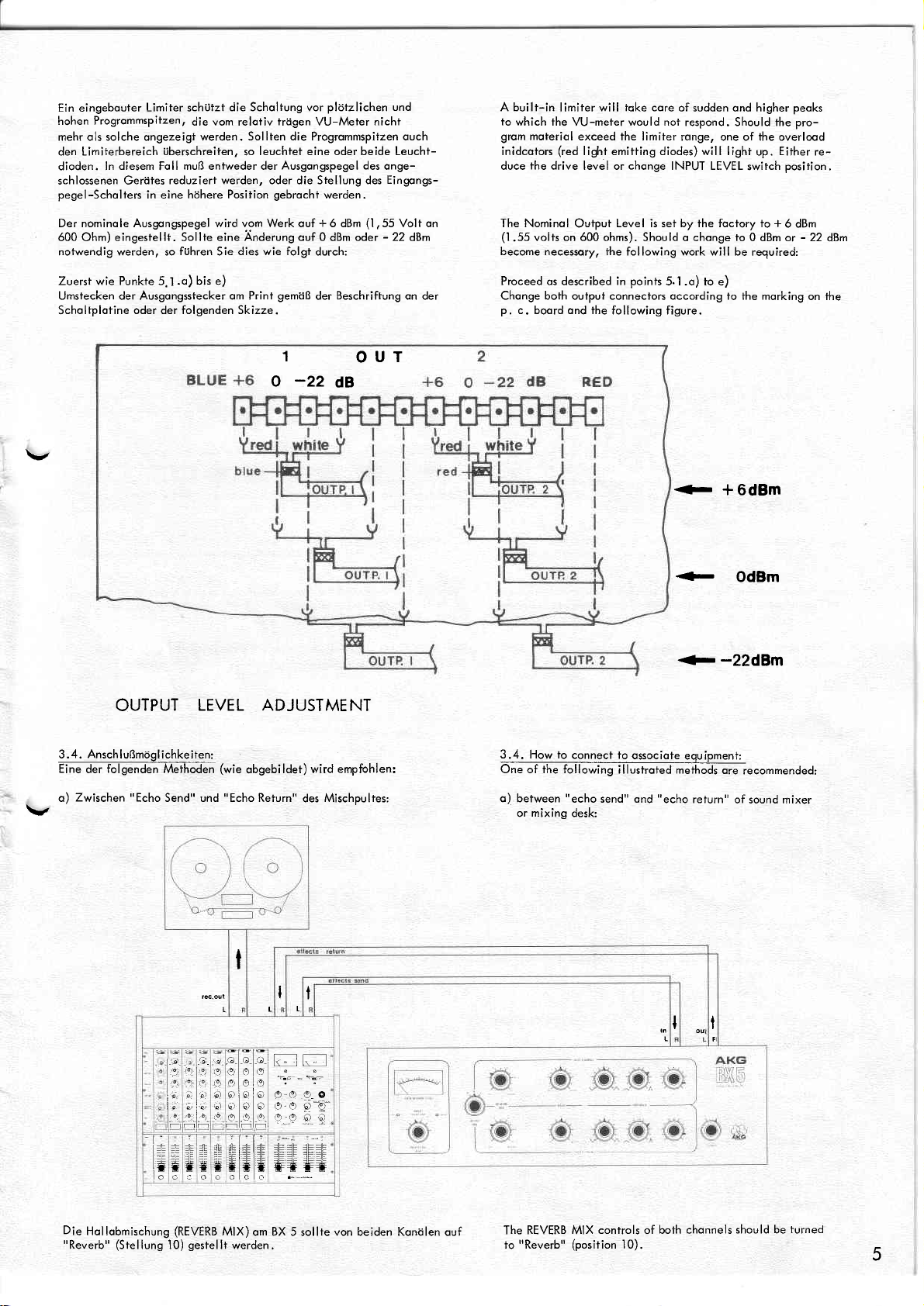
Der nominole Ausgongspegel wird vom Werk ouf + 6 dBm
600 Ohm)
notwendig werden, so
Zuerst wie Punkte 5.1
Umstecken der Ausgongsstecker om Print
Scholtplotine
eingestellt.
oder der folgenden Skizze.
eine Anderung ouf 0
Sollte
führen
Sie
.o)
bis e)
dies wie folgt
gemöß
1
-22
o
dBm oder
durch:
der Beschriftung on der
OUT
dB
(l
,55
-
Volt on
22 dBm
The Nominol
(1.55
become necessory,
Proceed
Chonge both outpui connectors occording to the morking
p.
on 600 ohms).
volts
described in
os
c. boord ond the
Level is set by the foctory to +
Output
Should o chonge
ihe following work will be
points
5. I .o) to e)
following figure.
<-
+-
+
to
0 dBm or - 22
required:
+ 6dBm
OdBm
-22dBm
6 dBm
dBm
on the
OUTPUT
Anschlußmtiglichkeiten:
3.4.
Eine
o)
folgenden
der
Zwischen
"Echo
v
LEVEL ADJUSTMENT
Meihoden
Send" und
(wie
obgebildet)
"Echo
Relurn"
wird
des Mischpultes;
empfohlen:
3.4. How to
^-
One of the following
o) between
or
mixing
connect to
"echo
send" ond
desk:
osociote
illustroted meihods
"echo
eouipment:
return"
ore
recommended:
of sound mixer
I
I
t
tlla t]]l
f
\- il\'
o e..o
o
o-o
e-9.
e,,90;l
lGl.f f;FlrF
t
lNf
lo
*,
i:.
t:
:!
It(-tf
il
Äi
iq
;,
==
-
lEf
t
::*t
'o
I
!9
e)
6)
6ri6rl6l
b)
ol616
e
:.lY
t!
tr#ffi
ff
oca
o
e
l9
_9.
o'l
i9
er.L
Die
Hollobmischung
"Reverb"
(Stellung
(REVERB
gestellt
10)
MIX)
werden.
om BX 5
von beiden Konölen ouf
sollte
The REVERB MIX
"Reverb"
io
(position
controls of both chonnels
l0),
should be
turned
5
Page 7

b)Zwischen Tonbond- oder Mischpult-Ausgong
oder
Verstörker:
"x.
AE
Aufnohme-Tonbondgeröt
und
b) Between tope
or
mixing
desk ond
recording
tope
or
power
omps:
Gr aa
o-o
919
;;
ols
't'
i,lni
6)
lo
;t-
.t-
916
--il'ri
rtn
;- l;
:F
t]
o
Die Hollobmischung
gewünschten
möß der
Es
wird empfohlen, Abhörversuche mii
kennboren Reglerstellungen
G.O
;l;
]E I;]E
* llll
*l*
oo
olo
(REVERB
"Rcumtiefe"
fl
#
o
MIX)om
zu beginnen,
RGtsr
O
E]E
olo.o o
o o
ö-9-_
9:9
A
-6-
s* s+
o
BX 5 sollte
für dos Progromm
den in
nöchsten
der
beiden
von
gewöhlt
Konölen
werden.
Abbildung
er-
ge-
The
REVERB
occording to the progrom
"depth".
is
It
odiusted
MIX controls
recommended fo
qs
illustrofed.
stort
@m
of both
moferiol
the
listening test
AKGi
BXP
chonnels
the
ond
should be
required
the
with
odiusted
opporent
controls
.t'
\t
v
*i,
--e
--.
-t
fi
I
t:
1l
BED
IENUNGSELEMENTE
I
. Wohlscholier fi.ir Eingongspegel
2. Hollzeitscholter
3. Regler für Hollintensittit
4. Tiefenregler
Mittenregler
5.-7
Absenkqn/Anheben
5.
6. Regler für
7. Regler
L Nefzscholter
Filtergüte
für
Filtermittenfrequenz
6
CONTROLS
l. Inpui level
2. Decay
3.
4, Boss
5.-7 Midronge
5. Cut/Boost
6.
7. Selection
B. Power
Time Confrol
Dry/Reverb
Frequency
norrow
Wide or
on/off
of mid-frequency
odiuslrneni
Mix
Control
controls
filier
response
of filter
Page 8

Bedienungselemente:
3.5.
Abhangig
stellungen notwendig sein.
gewünschten
vom
"Sound"
werden
verschiedene Reglerein-
3.5. Controls:
Depenai"g
conlrols moy be
o" the
required sound, devioting odiustments
required.
of
fhe
HALLZEIT
Pos. A:
KUrzesfe Hollzeit
Pos. B:
Mittlere Hollzeit
instrumente
onkommt.
Pos. C:
Longe Hollzeit
großröumigen
Effekte.
TIEFENREGLER
Der Klongchorokter
hangen
Der Klongchorokter
TiefenTiefen
sichtig eingesetzt werden, do dos Endresuliot
könnte.
Eine Absenkung
bi I d spez ie | |
MITTENREGLER
Dieser
nolonteil
o)
ouf
geben
b) Filtergüte
(DECAY
(einstellbor
und Mittenregler verursocht
("boost")
sehr effiziente,
entsprechend
Absenkung
Art,
iene
wird.
konn in einem Bereich
=
(reloriv
l0
Q
Genoue Filterkurven
TIME):
(co.
1 Sekunde) fur
(co.
2
wo es besonders ouf Klorheit
(co.
Klongchorokter
(BASS):
bei
oder Anhebung
(Symbole
Sekunden) für
3 Sekunden)
des obgemischten Tonsignols
über REVERB
wird ober ouch von der Klongfärbung
wird die
("cut")
(MIDRANGE
die durch die
Tiefenonteile
erzeugt normolerweise
percussivem
sieil verloufend)
Progromm
):
porometrische
Einstellungen
der
(Symbole
^
./L
von
Q
können Sie in der
Sproche
Gesongsstimmen oder
fur
iedes
(Kirche)
erholten
MIX oder om Mischpult).
werden können. Eine Anhebung
des
-Arloterio
Enizerrer
Einsfellung der beiden onderen
)
V "z\
=
(floch
I
kontinuierlich
des resultierenden
Progrommoteriol,
Signols betonen und sollfe
on den
verloufende
Grofik
oder Gesongssiimme
Musik-
Klongs
dos
soll bzw, für besondere
wird
vom
leicht zu
verschwommen klingen
ein besseres
|
.
veröndert den
drei zugehorigen Reglern.
)
Filterkurve) bis
eingestellt werden.
ouf dieser Seile sehen.
einen
Hollonieil
obhöngen,
und kloreres Klong-
verhollten
Regler vorge-
ob-
die mit
der
nur vor-
Sig-
zu
DECAY
TIME:
Pos.
A:
Shortest decoy
trocks
.
Pos. B:
/vledium decoy time
instruments,
Pos.
C:
Long
decoy time
which
should be proiected
speciol
BASS:
The
reverberoted
reverberotion
MIX
or on mixing
The sound
BASS
ond MIDRANGE
occentuote
be used
Adiustments
er resulh,
MIDRANGE:
This quite
verberont
o)
Cut or Boosf
in o monner,
two
b) Filter
moy
oggeroted
The
time
where clority of the
effects.
odded to the
will olso
the low
with core,
towords
especiolly
effective poromefric
sound occording
(symbols
controls.
be
filter
which depends
Quolity
odiusted continuously
filter
response
(opprox.
(opprox.
(opprox.
sound
desk
depend
frequency content
otherwise the finol
"cut"
(symbols
slope) to
I
second) for
2
seconds) for
3
seconds) for
inio o
will depend
"dry"
controls).
the
on
controls.
will usuolly produce
percussive
with
equolizer will
to the
\./ A
on ihe
^ /L
=
Q
curves moy
speech or
sound imoge is
lorge holl,
originol
colourotion
Adiusiments
ihree
from
l0
be
vocols or ony
ony
greotly
on the omount
(odiustoble
of the
result moy
progrom
confrol
)
sefting of the
)
Q,= I
(shorp
filter
seen in ihe
(smooth,
vocol
moteriol,
on REVERB
by the
ond
be too
remoining
nor
other
for
of
should
,'muddy".
cleor-
re-
ex-
below.
of necessity.
progrom
colhedrol.or
odded
towqrds"boost"
signol
befter ond
moteriol.
confrol the
settings.
with sreep
grophics
will
slope).
c) Frequenzeinstellung:
zwischen
Dos
iechnik
Jede
obmischreglers
ergebnisse erreicht
gewünschten
Response
Parameter:
500
Filter fur
oder für
Einstellung
Wert
of Parametric
und 5.000 Hz
den Mittenbereich
die Roumokustik
on den Filtern
durchgefUhrt
werden. Donoch
gebrochf
Level:max.
boost
:
O
:500H2
f
Um die
werden,
werden.
1,5
and 10
verschieben
Equalizer:
Mittenfrequenz
ist
vergleichbor.
sollte in
and
zu
durchous mit
der Siellung
domit beste AbhOr-
konn die
Hollobmischung
cut
des durchstimmboren
können.
Entzerrern
der
Studio-
"Reverb',
des
und Feineinstellungs-
wieder ouf
Filters
Holl-
c)
The
euqolizers
Any
den
in
filter
mix or
Parameter:
Frequency confrol:
ween
500 Hz ond
MIDMNGE
odiustments
posiiion
response
"depth"
1 ) Level:
filter
for
studio
should be
"Reverb"
ond then
:1
O
:5000H2
f
max.
boost and cut
to
odiusf mid-frequency
51000 Hz.
is quite
recording
for monitoring
comporoble
work or room
done with rhe
should be
purposes
set
and 10
to the
ocoustics.
REVERB
ond fine
fo
the
required
2) Level:
O
f
5 000 10
of the filier
ones
used in
MIX conrrol
iuning
dry/reverb
medium
boost
:1
and
5000
000
bet-
of
and
10
Hz
cut
7
Page 9

SCHALTUNGSBESCHRE IBUNG 4.
4.
Eingongsverstörker
l.
Dos Stereo-Eingongssignol
scholter S
mittefs
2.
LED-Ubelsfeugungsqnzeige 2. l.EDjn4lj:otion
Die
pegel
201
Operotionsverstörker ICA
zeigen
LEDs
on, die zu
fUhren können. Positive Signolspifzen
über R 217
mit Pegelobschwöcher
Eingongstronsformotoren.
on die
Pegel von
Verzerrungen
(R
225) negotiv
gelongt
tiber den
gemeinsomen
Die Verstörkung erfolgf formers by o common five-position
(lCB)
mehr ols I 7
dB über dem nominolen Eingongs- The
im
Limiter oder den
scholten T
Ausgongsverstörkern nominol
201
vorgesponnt ist. Die LEDs
Pegelwohl- The 2-chonnel oudio
(T
203)
durch, der limiter ond output
dodurch über
werden
I202F 204)einsescholtet.R2lS/C207,ß226/C2l'l)ermöslichenlönsere
AnzeigevonSignolspitzen.
3, Limiter
--DäTimiterverhinderfÜbersteuerungdesHollsystemsdurchProgrommspitzen.
T
l0l orbeitet ols
wird vom
Ausgong
Klirrfoktor im Begrenzungszustond ouf Minimum obgeglichen
4.
VU-lv'leter 4.
-Do-;vÜ:IGterzeigtdieHol|oussfeuerUngon'|Cl02richtetinVer-Useofdiodes
bindung mit D
A4efer on. Mit P
Aufsprocheverstörker 5. Amplifier driving the mechonicol
5.
---Üc-rPT0';ril;aNf-Signo|osymmetrischoufbeideAufsproche-vingomplifiers
verstärker
Hollsystems
des
6. A4otionol feedbock-Kreis
pegelobhöngiger
lC l0l ongesteuert. Mit P 102
von
105 dos Nf-Signol
lO4rlD
konn die
l0l
(lC
103) oufgetei!f, die die
Widerstond om
Anzeige
Rahmchen
gleich
korrigiert
Eingong
von
lC l0l
und
und C 136 konn der in
(
und sfeuerf
werden.
dos
0, l%)
VU-
werden.
(Aufsprechspulen) (lC
speisen. system.
(MFB)
und Hollze 6. lr4otionol feedbock
CIRCUIT
l. InputJcre-gmplifier
DESCRIPTION
wifL input level confrol
signol is switched to the input frons-
Amplificotion
is rolized
by
of input siglol
peok
LED indicotes input levels
input level ond indicoles
omplifier
peoks
will
octivote T
201
supplybyR2lTß220).Thiswill couseLEDD20l
lishtbyT 202(I 204).R218/C207(R226/C
for longer
circuit
3. Compressor
-TfffiTter;i'dfpreventsoverloodingofthereverb-sysfemby
oudio signol
the
input circuit of lC l0l ond is controlled by o level
indicotion of signol
Limiter
peoks.
T l0l
sensitive curcuif ot the output
ponents
P 102 ond C 136 minimize distortion
mode
sion
VU-meter
ö/")
(
0.1
indicotion of
reverb
D 104 ond D 105 ond drives the
brofion use P l0l.
103) which operote
the drive
(MFB)
eiten erfolgt e,rerb
durch verschiedenortige
Verschiedene Frequenzentzerrungen
trogungsverholten des
Anpossung des Nf-Signols on dos Hollsyslem.
gleichen
Federnsystems
bei den
dos unterschiedliche
3 einstellboren
Hollzeifen of fhe mechonicol spring system
mode
is
by vorying
Über- Speciol frequencyequolizotion compensotes trqnsmission loss
omp motching fo the
time
ous. settings.
den
7. TTL-Spring
The mechonicol
system
spring sysfem works
fhe BX 10, BX 15, BX 20, but there
the BX
5. Precisely
odiusted twin
the
technique in
duces very smooth
--T6ä
rd;Elprlng output signol is
qddition
ond homogene
trimming
to o
potentiometer
echo effech coused by smoll voriofions
in the mechonicol
reverb
7. TTL-Federnsystem
Dos
Federnsystem entspricht
wendeten, ist
sproche
iedoch
wie ouch die
den Federenden durch
wird in Verbindung
gleichfOrmige
Abnohmeverstörker 8. Pick up omplifier
8.
---E;T6äEmeversffirker
Mischverstörker
mit
und weiche Verhollung des
l0t. P
lC
enzen im Hollsystem, die
pegel
um co + 2 dB verönderl werden.
im Prinzip dem
BX 5 nur einkonolig
im
im
ousgeführt.
Abnohme des Nf-Signols
genou
speziell
iustierte
Doppelröhmchen
beorbeiteten Federn eine oußergewöhnlich
Nf-Signoles
104
lC
l04
Echos
speisf den
dient
verursochen
motionol-feedbock-Kreis
zum
Ausgleich von
können. Mif P 105 konn der Holl- circuit. The
BX
10,
erfolgt
BX 15, BX 20
ver-
Sowohl die Auf- used in
gleichzeitig
(Spulen).
ouf bei- in
Dodurch signol ot both ends of
erreicht.
und
Übertrogungdiffer- into the mixing circuit lC l0l ond olso
verb signol of+ 2 dB con be
9. Porometrischer Eauql izer
Der porometrische Equolizer ist eine Besonderheit des BX 5.
Konol ermöglichen
o)
Verönderung
P 208)
b) Verönderung der Filtergüte von
Anhebung
c)
(P
207/P 210)
der Mittenfrequenz des Filters von 500
=
l
Absenkung bei
oder
Q
der
l0
...
gewöhlten
(P
Filtermittenfrequenz + l5 dB
10. Bossregler
Der Bossregler
erloubt
die durch eine Verönderung der
(lCB)
erreicht wird.
FT-F@.r^oglicht eine stufenlose
zu verhollfem Signol,
Ausgongsverstörker
12.
-rct
(lC
D)
Übertroger
om
Ausgongspegels
spei-den
reduziert
erfolgt
Drei Pegelwerte
(
-22,
Anhebung bzw. Absenkung von + I0 dB
eine
Gegenkopplung om Operotionsverstörker ICA
Überblendung von direktem
Ausgongsübertroger.
Klirrfoktor
den
Eine Gegenkopplungswicklung lC C
Ausgongssignols.
des
durch Umstecken von Printsteckern
+
0,
6 dBm)
stehen
zur
Verfügung.
9.
Midronge
Three
Hz
Drei
-
5kH'z
pro The porometric
Regler
(P
205, o) Shifting of filter resononce frequency from 500 Hz
206/P 209) b) Wide or norrow filter
c)
100
Hz.
10. Boss control
The boss control P 203
quency
dependent feedbock
Reverb mix control
I I .
--FT0TlPrdZfterm'rts
to
12.
Output
use of o speciol
To
Nominof
bei
Die Wohl des
Hollprint
om
Signol
poromefric
potentiometers per
5,000 Hz by P 205
equolizer
equolizer
(P
208)
response
(P
209)
Continuous cut or
sononce
frequency
cuf or boost
reveöerotion
oTplifier with output level control
(lC
D) drives the
select output
oufput
boost
(P
207/P 210)
(P
(+
l0 ag ot
on ICA
continuous
only.
oufput
tronsformer
level replug output
levels ore
level swifch
l/2
OP-ompl. ICA
(S
(l/2
201).
ICB),
geoks
higher
possible
sections. Positive
203)
which is biqsed to
0
thon I 7 dB obove
distortion
in
oudio signol
negotive
(D202)to
2ll)isostoroge
peoks.
qs
works
level dependent
o
l0l . The
of lC
resistor
feedbock com-
the
in
compres-
drive level
VU-meter. For level coli-v'.
spring system
coils of the mechonicol
with
time
reverb
of
different reverb
on the
odiustment
reverb
syctem.
time
principle
some
is only on chonnel
feed ond
coils
spring simultoneously.
speciolly
prepored
pick
(potented)
This
spring system
reveöerotion.
omplified by
bock
P 104 ollows
of
lC
into
signol
104
ond fed
the
MFB
reducing
tronsmissic
system. Level voriotioris of fhe
mode
is o
speciol
chonnel ollow
obout + 15
of
204) ollows continuous
(lCB).
trqnsformers.
winding
-22,
P 105.
vio
feoture
-
(a
10
...
ot
dB
100 Hz)
by use of
fode-over from
(on
Feedbock by
signol distortion.
reduces
cobles
+
0
6 dBm.
ond
the BX
of
up
l) by P 206
selected re-
low fre-
frequency
"dry"
p.c..b.)
the
spring
os
up
re--
5.
to
signol
the
pro-
Page 10

5. REPARATURANLEITUNG
5.1 . Zerlegen des Gerüfes:
5. REPAIR
5.'I
INSTRUCTIONS
How
to
.
dismontle BX 5:
o) Vergewissern Sie sich,
dem Neiz verbunden ist.
b) Entfernen
Fingernogel
mit einem kleinen,
Sie
groue
die
oN/oFF)
c) Lockern Sie
den Knoof.
d) Entfernen
olotte.
e) Nun
f) Entfernen
g)
h)
5.2.
können Sie die Frontplotte,
ous dem Gehöuse ziehen und vor
tine, die
Ziehen Sie
Um die
ongebrochten Schrouben
Holleinheit
dem
Gehöuse.
Beim
Wiedereinsetzen Gummiplöttchen
gleitföhig
Seife
Umstellen ouf
Arbeitsgönge
Noch
dem Entfernen
Sponnungsumscholtung
Gehen Sie, bilte,
Schroube unter der Abdeckung
die
die
Sie
sechs
Sie die vier Schrouben der Eingongs-/Ausgongs-Sfeckerplosich ouf der
Netzteilploiine
die
Holleinheit
durch öffnungen in
Nicht
mochen.
'l
l0/220 V Netzsponnung:
bis
o)
doß dos Neizkobel ouf keinen Foll mit
Gegenstond oder dem
Abdeckung om Netzscholterknopf
großen
Rückseite
ouszubouen, losen Sie
der
om Anschlußkobel ziehen
g)
der Abdeckung
durch
gemöß
spitzen
Kreuzschlitzschrouben
gemeinsom
dem
des BX 5 befindet.
ous dem Gehöuse.
Befestigungswinkel.
der Gehöuserückwond noch
Umlöten
der folgenden
mii zwei
Gehöuse
die
on der
on der Netzteilplotine
Drohtbrücken
der
Skizze
und entfernen Sie
oblegen.
zwei
Donn drücken
! !!
Holleinheit
vor:
(POWER
on der Front-
Scholtplorinen
om Gehöuseboden
vorn'e ous
mit
etwos
konn die
erfolgen.
Sie die
o) Moke
b) Remove
c)
d) Remove
e) SIide
f) Remove
S)
h)
5.2. Chongeover to
certoin, thot the power
connected to ihe
with the oid
grey
noil ihe
Loosen the
knob,
the
ponel.
the
out
boords
ond
the four
boord
Slide
For removing the
of the ongle
of
ond out of the housing,
ponel. Do
When
ber
bock in
Procedures
Remove
boord
occording
the following groph:
the bock.
ot
fhe tronsformer
out
the
housing.
replocing the
squores fitted to
eosily.
protective
with pliers
to the
moins
outlet.
of o
lid of the POWER
screw underneoth the
lorge
six
froni
ploce
screws
brockets,
Push the
pull
not
I l0/220
g)
to
o)
smoll obiect or your
Phillips-heod
ponel
togefher
it in front
reverb
cover oi the bock
ond resolder the
required operoting
of
the
of
boord
system, unscrew fhe two
qre
which
spring sysiem toword the
fhe
using
ot the
connection
system, opply
it in order to moke
V operotion:
coble
is in no
ON/OFF switch.
lid
ond toke
screws on the
wifh the
the
inpui/output
from the
locoted
openings
smoll
two p.
housing.
connecror
housing.
on the botiom
in the
coble
some
! ! !
soop
the
sysfem
of the tronsformer
iumper
voltoge
os
woy
finger-
off
to the
leods
shown in
the
front
c.
bolts
front
reor
rub-
glide
"
"
220V
OPERATION
\,
"ll0v"
OPIRATION
Donoch
konn dos
Punkten
o) bis g
Überprufen
I lten
ste
Betriebssponnun g:
Betriebssponnung
110/120 Volt
220/2&
Benötigtes
o)
b) Normoler
c) Lotkolben
d) Kleine
Werkzeug für diese Arbeiten:
Kreuzschlitz-Schroubenzieher
der Frontplofte
Flochzonge
Hollgeröt
zusommengebout
)
Sie noch den Sicherungswert
Yolt
.
Schroubenzieher
in umgekehrter Reihenfolge
werden.
S icherungswert
0,2 A trtige
0, I A
hage
fur
die sechs
zu den
entsprechend der einge-
großen
Schrouben on
Assemble the
o) to
Check
voltoge:
operoiing
10l120
I
220/240
Required tools
o)
Phillips-heod
ponel.
b) Conventionolscrew-driver
c) Soldering
d)
Smoll flot
reverb
s).
the oppropriote
voltoge
volts 0.2 A
vol+s
for this chonge:
iron
pliers
unii in reverse
screw-driver for six lorge
fuse
fuse rofing
0.1 A
sequence
rofing for the
slow blow
slowblow
poinfs
of
sef operoting
screws on fronl
9
Page 11

Hinweise zur Fehlersuche:
5.3.
Blockdiogromm ist ein
Dos
ein defektes Geröt
Funktionsstufe
proktisch unreporierbor,
sind
zu lokolisieren.
Die folgenden Tests bei
helfen,
Fehler im BX 5 einzukreisen.
reporieren
Fehler liegen
der
wertuolles
ongeführten oufiretenden
den
Hilfsmitiel
zu können,
könnte. Brumm,
mon
wenn
sich
isi es wichtig
nicht die Zeit
bei
Fehlersuche. Um
der
zu
Rouschen oder
wissen,
nimmt, den Fehler
Symptomen sollen
in welcher
Aussetzfehler
How to ldentify
5.3.
The block diogrom will be of
In repoiring
funciion unit
mittents
lize the foult.
The following
you pinpoint
o defective device.
ore
virtuolly
Defects:
ihe defeci
list of symptoms ond fhe
defects in the BX
might be
irreporoble unless
greot
help in locolizing defects.
it is importont
locoted.
5.
to know in which
Hum, noise, or
toke the time
you
occording tests
will
inter'-
io
loco-
help
Kein Ausgongssignol:
VU-Meier-Be
1. Sicherung ersetzen
vergleichen, folls erforderlich, umstellen)
2.
Versorgungssponnung
und
VU-lv'leter
Keine
1. Zuleifungen zum BX 5 überprüfen
2. Eingongsstecker
Aussleuerung om
Ausgongsstecker hot
Kein Hollsignol on beiden
Stecker des Hollsystems locker
l.
2. Limirer
3. Mischversiörker
Hollsignol
Ausgongsverstörker
1
.
übersteuert
2. Limiter defekt
3. Aufsprech-, Wiedergobe- oder Mischverstörker defekt
4. Hollsystem beschadigt
Hol
lechos
Hollsystem
I .
Stift
Stift 6,7/8,9
Bei Kurzschluß
2. P
104,
Aufsproche-,
3.
4. HollzeitscholterS
leuchtung brennt n icht:
Houpfprint überprüfen.
Beleuchtung brennt:
Aussteuerung
(1/2
verzerrt:
bei
(vnten)
1,2
.|03
P
(om
Geröt eingestellte Sponnung
I5 V om Verbindungskobel zwischen Netzteil
J
om VU-Meter:
BX 5 hot
im
-Meter
VU
gel
sich
Ausgöngen:
lC 101, T 1 0l ) defekt
(1/2
lC
durch
(-JEingongssignol
impulsförmigem
(Spulenwiderstönde
defekt
-
4,5
-
(oben)
oder Unterbrechung:
folsch eingestelli
Wiedergobe- oder
l0l defekt
gelöst.
sich
vorhonden:
ost.
l0l)defekt
moximole
reduzieren!
gongssignol:
Ein
260 J 10
195 ! 10
Mischverstörker
Frequenzonhebung im
)
om Hollstecker überprüfen:
o/o
o/o
Hollsysiem
touschen
defekt
mii
Netzsponnung
Equolizer
No
VU meter is
I . Reploce
2. Check
VU
No
l. Check
2.
Signol is indicoied by
Output connector come off
No
l. Reverb
2 . Limirer
3. Mixer
Disiorted Reverb
I
.
2.
3. Reverb
4. Reverb
Pulse-shoped
I . Reverb
connecior: pins
When short-circuit
2.
P 104,
3. Reverb
4. DECAY
Signol:
Output
not illuminoted:
(check
fuse
not,
lf
rewire
voltoge
supply
ween the power
meter
signol reqdout:
Input connector
Reverberoted
iOutpuf
in the equolizer
Limiter is
voltoge
tronsformer
is illuminoted:
input lines
system connector is loose
omplifier
drive, pick-up,
syslem is domoged
sysfem is defective
P 103 odiusted
drive, pick-up,
come off
Signol
(l1Z
lC tOl , T l0l
(1/2
Signol:
omplifier
defective
Inpui Signols ploduce
I
pins
6,7/8,9
or interrupted:
TIME
swiich S l0l
whether
W meter:
ot
lC
overlooded by moximum
(J
,2
moins
selector)
(+/-15V)
either
)
101)
reduce input
or mixer omplifier
(check
(lower)
(upper)
incorrectly
or mixer
voltoge
olong
ond fhe
moin
outpuf:
is defective
is defective
signol!)
Echoes:
coil resistonces
-
4,
260
5
-
195
reploce reverb
ompl ifier
is defective
seiting is correct.
connection
p.
c. booro
frequency boost
is defective
+/-
ohms
ohms
10 V"
+/-
10
system
is defective
coble bef-
on
reverb
y"
\t'
i
q
t
t
Rauschen om Ausgong:
Hollregler P 201/P 202
Eingongsverstörker des entsprechenden
defekt.
Holfregler
Beide Konule gleich:
l.
2.
Konöle
Fehfer im Klongreslerteil,
kurven überprüfen.
Verzerrungen bei höheren Ausgongspegeln
Ausgongsverstörker
Ausgong
Ausgongsverstörker
Messungen
S 201 ouf
speisen, P 201/P
Meßpunkt:
P 2O1/P 202
Limiier
rouscht
Wiedergobeverstörker
verschieden:
schwingt hochfrequenr:
om
Verstörker:
-22
dB
ouf Linksonschlog:
ovf
(T
l0l,
lC l0l)
(lC
on HO
(NE
540) defekt
schwingf
stellen. In beide Eingönge
202 Linkson-schlog.
Ht
Oy
lC l0l Pin
Hollstecker:
HollzeiiA:
-"-B:
-
olle Pegelongoben +
r^.
IU
l dB
Ausgong
(Konol
Konols
Rechtsonschlog,
104) oder Mischversiarker
1,
(NE
540, C 214,
1/Ht 2
'l/Oy
2
Siift 7,
"
-
C
Klongregler
HO
2 Signol
und direktem
C 228)
62 nY,/1kHz
-4
:
dBm
+3
:
dBm
13 : +10
9
:
+3,5dBm
_l,5dBm
-3,5dBm
:
: nom'
dBm
Pegel
l:lCA,
Mittenstellung:
(lC
l0l)
einspeisen
Signolweg:
-22
(
(+
6' 0'
Konol 2:lCB)
defekt
und Filter-
dBm) ein-
-22
dBn)
Nlgq
Pyayl
Reverb
Mix controls P 2Ol/P
Input omplifier
ICB) is defective.
Reverb
Mix
controls in
Equol noise
l. Limiter
2
Pick-up
.
Different
Foulty
fil ter
Dislortion
Outputomplifier
Outpui
Outpuf
Ampl
Set 5 201
inputs, P 201/P
Test Point:
All
controls P 201/P
center
levels
generotes
omplifier
noise
tone
control sfoge,
curves
with high
Oscillofes
ompf
ifier
if ier
Meosurements:
-22
for
Reverb
level figures +/-l
202
of respective chonnel
posifions:
in both chonnels:
noise
(lC
levels:
Oufput Levels
(NE
540) is defective
wifh High
oscillotes
dB.
Feed 62 nY/l
"DRY"
202
in
Hl l/Hl
Oy l/Oy 2
lC
Connector:
Decoy
Decoy
Decoy
dB
in
202
in
(I
l0l,
104)
or mixer
feed signol
Frequency:
(NE
540, C 214,
position
2
l0l
pin
Pin 7,9
Time
Time
Time
Output
lC
13 :
A : +3.5
B :
C
"DRY"
position:
(chonnel
"REVERB"
l0l)
omplifier
HOl, HO2ond
into
ond Direci
C228)
-22
(
k1z
-4
:
dBm
+3
:
dBm
+10
-l
.5
-3.5
:
: roied
level
l: lCA,
position,
(lC
Signol
d}m) inro
dBm
dBm
dBm
dBm
(+6,
chonnel 2:
rone
I 0l
defecrive
)
check
Poih:
b o r h
-22
0,
d\n)
1--
;
r
)-
-.l
Page 12

Abgleich:
(nur
noch Reporoiuren
-YU:l&!sL
Beide
Eingtinge:
P l0l
Limiter:
Beide
Eingönge:
Klirronolysotor
P 102,
Konfrolle:
Echokompensotion_:
Beide
Eingenge
201/P
P
P
103
..
P I04
\.
Hollpegel:
Beide
Eingönge:
P 204,
.l05
P
-22
:
VU-Ä4eter ouf
C'136
Ansprechschwelle
bei
202
(fein)
(grob)
P 207,
:
dBn/l
-5
dBm/l kHz, Hollsystem
on Hollstecker
: Mii beiden Reglern
einstellen
obigem
-22
:
dBm/Burstsigno
suf Rechtsonschlog.
Mit
:
Hollecho
-22
dBm Terz/Oktovrouschen (500
p
210
Mitte,
Durch
Pegelvergleich
(P
Signol
onschlog)
bzw. Austousch
kHz. S l0l:
*3
dB Anschlog
Stift 7
(<0,
I
%)
"overlood"
der
Pegel
| . Hol lsystem
Ausgo,,s
beiden
Reglern
obgleichen
P 202
von direktem
obwechselnd
(Bereich
201,
einstellen
des Hollsystems
-22
dBn
einsfellen
obstecken
oder 9 onschließen
Klirr ouf
Minimum
LEDs
ldB)
ft
ongesch lossen
mit
Kopfhörer
ouf minimores
(Normolsiellung:
Hz),
und
verholltem
Rechts-
2 dB)
t
durchführen!)
obhören.
Mirte)
p
203,
und Links-
A
lignment:
(only
ofter
repoirs, or
lvleter:
VU
Both inputs:
P l0l
Limiter:
Boih
Connect
P 102,
Check: Response
Echo
Both
201/P
P
tor
output
P 103
P 104
Reverb
Both
-22
odiust
:
-5
inputs:
distortion
C 136
: Adiust
should be ot obove
Concel
lofion:
-22
inputs:
inputs:
202
in
signol
(fine)
(coorse)
Level:
-22
P 203,
P 105
"REVERB"
replocement
d}n/1 kHz.
meter
VU
dBm/1
both
ihreshold
d}m/bvrst
:
d}n
for
kHz,
onolyzer to
Use bofh controls
minimum
disconnect
hormonic
confrols
of
meniioned
signol,
posiiions.
echo
one-third
P 204, P 207,
: od[ust
Ievels
(P
201,
positions)
DRY
of the
-22
S l0l
:
+3
dB
reodout
reverb
reverb
connectoi,
distortion
(<0.1
%)
"overlood"
level
reverb
Use heodphones
to olign
(normol
octove/octove
P 210
(wirTrin
+/-2
of direct ond
P 202
olternotely
reverb
system)
dBm
system
pin 7
to minimum
(y'-
LEDs
system
connected.
for
position:
in
center)
noise
positions,
center
dB) by
comporing
reverberoted
in REVERB
I
dB)
ro
moni-
(500
or 9
using
Hz)
signols
ond
Blockschol ibi ld
\,
I
2
4
5
7
I
l0
ll
tl
gsverstörker
E ingon
-Übersteuerun
L ED
Kompressoy'Lim iter
VU-lrleter Anzei
Aufsprechverstörker ftir die
Motionol Feedbock
TTL Fe'dersystem
Abnohmeverstörker
Porometrischer Entzerrer fi.ir mittlere Frequenzen
Ti efenreg I
Ho llmischeinrichtung
Ausgongsverstörker
mit Eingongspegeleinstel lun
gsonzei ge
ge
Hol loufsprechpegels
des
Holleinheit
(MFB)
Vemtörker mit
ernetzwerk
mit Ausgongspegeleinstel
Hollzeiteinstellung
lung
g
(om
Ausgongsprint)
Block diogrom
I
-tl--
-ffl
pre-omp
I Input
2
peok
LED
3 Compressoy'Limiter
4
VU-meter indicotion of
5 Amplifier driving
6 Motionol feedbock
7
Mechonicol spring
Pick
B
up
9
Midronge porometric equolizer
Boss
l0
I I Reverb mix control
12
control
Ouiput omplifier
with input level control
indicotion of
the mechonicol
(MFB)
system
omplifier
with
input
signol
the
reveö drive
with reveö
output level
level
spring sysiem
fime odiustment
(on
confrol
p.c.boord)
lt
Page 13

@
x
(rl
a
F
n
o
!',
o
ctß
N4148
N4148
I
I
c
o
ööäö
ÄONJ
>on>
\S+\
s$$s
R=oP
\
-N
-N
x
--x
*
o
N
@
12
Page 14

Täf
l6l
Ni
xi
Ni
I
L___
z
z
oN
91
66tqs
an
s;
ox
I
:
do
<U
LJ(J
ccz P-
o
o
d
2
:
.
lo
x
@
(!02
ü0e?
(n06
012
t\f
E
o
,rö
l3
Page 15

Flr
t+
ooo
-@E-
3:;ä:;;;;
@
{IIEF
ra|
L+r
E
*
r_*@
El
Fl
rgrEl
LlJ
HHH
@bl
@
H6ttr*
-,*
ELmgF| ffi*
ffEEl
^-r+
#%#HHH$gHH
%*
*€SEL
-{le-R--+
@-@-'n\
@x rE
.ransL@Fs
W^ l-J@ E+
(
\
H
Bffi
P-
YY &Eb
\**Y
U
)HbIH HH
o
/. n,,t
-:-
*_
E|EI H #i n
HH
...4g
HHIiI
H,'
Li-
GlrF +
Fl
HsHH
l"
hJl
'
Fg El
Pl
4\ Ä-
(R
\:_/
-1.-931!!-
;
H f"-l
-rg-
H
/;\
(R
\:_/
*
--rznaL
(p
\:_/
JTE 'L
-EE+-
o
ittrF llt?aF A
:- l$l
äEl
15-
I t$l
til
H
Y
-+4
-+E-
TL-l
lol
lla
bs
--*-
-#&
) AÄ,
lil6 |
FHH
TT'
tfr T;l
l. s I
lEl
lr
II
t$ Hl
flY
)
II
tüt tg
----N
Ft
q
| |
I
lil ü 1.'I trfr
rJ,ryE
f
T
lltl
I
{E-
töl
t!_:_l
:*_
$H$
l=-l
l.s I
HH
SI
$i$-$
ITIIIF
'
T
Fä*
H
@$l
ffl
LIF
@_
I -_-j
r
lfl
@-HüüH
äIEF
/:\ fi fr--t=+ /:\
e,
-€EilF
-€EF
_@-6\
tr\ZH
rä
rfl
-ED
{h^--
EED
----
f
--r6r?E- T -@-
--r*nil-
f**'*-
$l
| _-@lF
|
L.@G.
eM-,Hll u
6 ffil
T H Y f:.r /'t\ \e
*r
-ruF
--1-!]L!F
{Etrf-
w%#
r;\
v
-Ir.g.Jü-
{rd-
A
\-/
-EmF
{F8-
@E-
-€EET-
A
v
{3ilEF
*
@
@fr_-*--
EO
-'är*t*-
+
H
H
+
e,
\-)
üü ] T
YY I I
El
.S
|
I
f,i.
F
r,
il
\t
v7
14
F.l Y=HHgH
+h1 hl**wm F-
-
ÄF]
rlEll
:li:J
Bl
E-€
HI------_l
l"l I
il-ö] I lHl I
-:L,]
cl l*l I
?ryH
3*-
g; : g
I
$
3$
3
ä
$::
!
E=*
a
3
3
---*-dä
?i6=3i;s
oooooooo
lrl--L
FI HHIg
TTLT-
-:oa
oooo
Page 16

B. STÜCKLISTE
Gehöuse kpl.
Holleinheit X
Holtewinkel
Frontplotie
Knopf 6 mm
Knopf 4 mm
Mutternobdeckung
Koppe,
Reduziersiück
\
v
Reduzierhülse
Leuchfdiode,
Fossung
S icherungsho
Koppe fur
Koppe
Sicherung
Sicherung 0,2
Wondsteckdose
Wqndsteckdose
Netzkobel
Netzkobel
für Hol
schworz
grou
rot
blou
gelb
grUn
dozu
I ter
Sicherung
fijr
Sicherung
0, I A tröge
(BX
(BX
5
leinheit
(Kunststoff)
(lr4essing)
rot
5 x 20 mm
6 x 30 mm
(BX
(BX
A trage
(Srifte)
XLR
(Buchse)
XLR
5E)
5El
)
5E)
5El)
(BX
(BX
5E)
5El
8. PARTS LIST
Best.
Nr.
Order no.
/
2150
M 0501
210l M
l00l
2150
Z 0501
2150 Z
0201
0040 E 0556
0040 E
0555
0040 E
0557
0040 E
0550
0040 E
0551
0040 E
0552
0040 E
0553
0040 E 0554
0040 E 0558
0040 E
0559
2150
z 2701
0014 E 0041
0013 E
0052
0013 E
0068
0013 E
0081
0013 E
0012 E
0012
E 0012
0016 E
o0t7 E
0080
0001
0332
0317
)
0t l0 E 0009
0l l0 E 0012
cose
reverberotion
ongle
brocket
front ploie
knob, 6 mm
knob, 4 mm
cover
ring
cop, block
grey
red
b
Iue
yellow
green
reducing
sleeve
LED,
LED
fuse
boyonet
boyonei
fuse 0.'l A
fuse
connector
connector
power
power
piece
(bross)
red
-socket
holder
lock
lock
0.2 A
XLR
XLR
supply cord
supply
unii X 5
for X 5
(plostic)
for fuse
for fuse
slowblow
slowblow
(mole)
(femole)
(BX
(BX
cord
5 x 20 mm
6 x 30 mm
(BX
5E)
(BX
5El
)
5E)
5El
)
(BX
(BX
5E)
5El
)
Netzfeilprinf:
Netzfeilprint
Netzteilprint
\:
Tronsformotor
GleichrichterBS0CS00
Sponnungsregler
Sponnungsregler
Kondensotor
Netzscholter
Stiftleiste
Stecker
Koniokt
Houptprint:
Houpfprint
VU-lv1eter
.
Lompe
Abstondsbolzen
Abstondsbolzen
Buchsenleiste
Drehscho
Moniogering
Übertroger
Holierung
| 000
S
pol.
3
ftJr
Stromversorgung
dozu
kpl.
dozu
I ter
dozu
ü1,
dozu
kpl . I l0
kpl . 220
N
ll
W 301
302 78M15
W
/40
)JF
301
kurz
long
pol.
l6
ü2
V
Y
79M15
V
3 pol
Powei
2150
M 0302
2150
M 0301
1650 Z
0l6l
0014
E 0040
0015 E
1036
0015 E
1027
0039 E
1002
0040
E
0053
0018 E
0313
.
0018 E
0018 E
2150
0027 E
00ll
2150
9999
00lB E
'2150
2r5o
1650 Z
2056
0314
0102
M 0l0l
0002
E 50lt
Z
2001
N
0104
1600
Z 2101
z 2501
0154
Z
0801
p.c.b
p.c.b
moins
bridge
voltoge
voltoge
copocifor
moins
flot
wofer
housing
crimp
lvloin p.c.b
p.c,b
W-lvleter
lomp
spocer
spocer
connector
rotory
odopter
tronsformer
mounting
p.c.b
supply
complete
complete 220
tronsformer
rectifier B
switch S 301
for
terminol
complefe
short
long
switch
for
I l0
regulotor
reguloior
1000
yF/40
(3
pin)
crimp-terminol
(16
woy)
rotory
Ul,
U2
support
for
V
V
N ll
B0
C 800
W 301 79M15
W 302 78Ml5
V
(3
woy)
switch
tronsformer
l5
Page 17

I00
558
54{l
22
k lin
B
B
k lin
Potentiometer 2 x
Potentiometer 2 x220 k lin
Potentiomefer
Potentiometer l0 k lin
Rc 4558
tc
NE
tc
540 L
Kühlstern
Tronsistor BC
Tronsisfor BC
wzt E0027
0o2r E 0028
0021 E 0029
0o2l E 0030
0015'E l0l5
E l0t2
0015
00r 3. E 0021
0oro E 00s8
0010 E
0057
potentiometer
potentiomefer
pofentiometer
potentiometer
rc Rc 4558
tc NE 540 L
cooling fin
trqnsistor
tronsistor BC
BC 558 B
2 x 22
2 x 220
100 k
I0 k lin
548 B
k lin
k lin
Iin
Hollprint
Hollprint kompl.
Drehscholfer
Befestigungsring
ReduzierstUck
Achse
4 mm
Stiftleiste
Stiftleiste 4 pol.
lCpA 739 PC
Tronsisiör 2 SK30GR
Diode 1N4148
Übertroger
Befestigungshülse
Stiftleiste 9 pol.
Buchsenleiste
Konfoktstift long
Buchsengehöuse
Konfokf dozu
dozu
l2 pol.
9 pol.
4 pol.
ws
SD
gs
rt
or
bl
sw
gr
gn
br
Sh
Farbkodierung
weiB
ilbe
s
r
gelb
gelb-grün
roI
orange
blau
violett
scnwarz
grau
grün
braun
Schirm
2150 M0201
2150 Z 2102
2150 Z 2501
0040 E 0548
2150 z 2201
0013 E
0053
00t5 E
1002
0010 E
003r
0014 E 0017
r650
z 0t53
1971 Z Ogol
o0l8 E 0904
0018 E 0903
0018 E 0l0l
0018 E 0402
0018 E 0102
p.c.b
Reverb
p.c.b
complete
rotory swifch
odopter
för rotory
reducer
oxle
4 mm diometer
ffot
wofer 12
fJot
wqfer 4 *y
lC
,pA
tronsiitor
diode I N4l4t!
output tronsformer
mounling
pin
connector, 9
connector
contoct pin
housing
crimp terminol
woy
739 PC
2 SK3OGR
sleeve
strip, 9
(long)
for crimp terminol
Wire
colors
wnrte
stlve r
yellow
yellow-green
reo
orange
blue
violet
black
grey
green
brown
shield
switch
woy
urcy
of diagram
(4
woy)
.,!
\rq
J:
.*.
't
I
t
I
t
t
i
t
I
+
+
I
j
F
i
t
-f
!
L
i
lyl
.
i..
.!
{
t\
,t.
t
!t
16
Page 18

,
,I
,t
'
-
I
:::-l'9i
a:
'
""I
I
t.
,t
,l
-'1
L
'"j
'I
I
i
L
-
;f
t'f:\l
'*]
!
'.:.1
Technische Anderungen vorbehalten. We
A}<Gi
AKG Akustische u.
Brunhildengasse
(432221
TFi
956517-0-,
OOOTJSUIOS
Kino-Geräte Ges. m. b. H.
1, A-1150 Wien,
TX: 131839
reserue
the right to make technical altsration6.
Austria
a
akgac
',j
-j
,f
t'ä
*,
,
V.ä
'r
'1'l
li
j
;
l
j
t
I
g
,{
i
1
I
Ausgobe Dezember
1980
ETL
158
]I
 Loading...