

Page 1
DRIVING INSTRUCTION
REMOTUS MC8318
923477-000 USA
MANUAL MC8318 No. 923477-000 USA
Version: A0 Approved by: HH
Page. 1 (12)
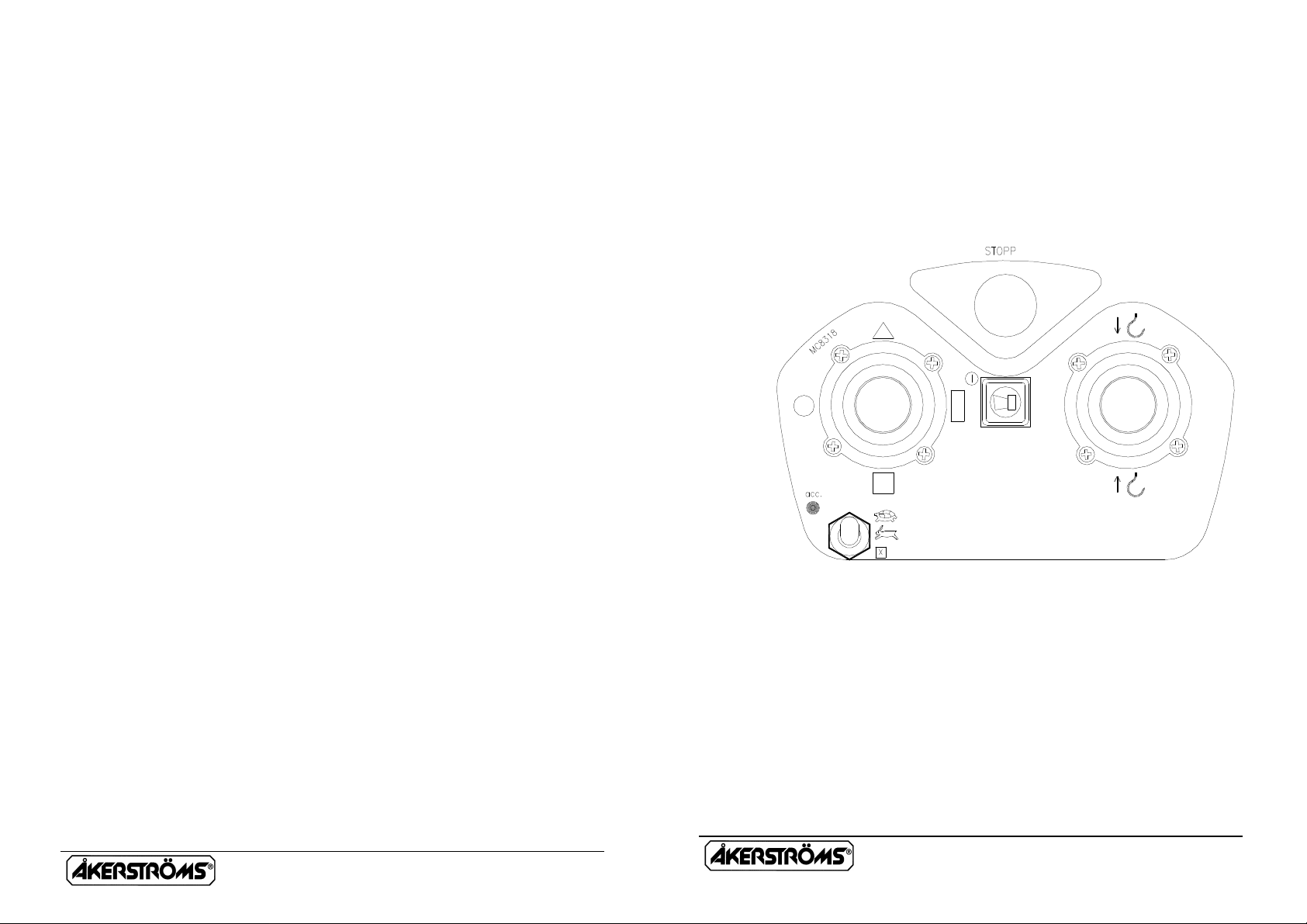
Variant 1
MANUAL MC8318 No. 923477-000 USA
Version: A0 Approved by: HH
Page. 2 (12)
Page 2
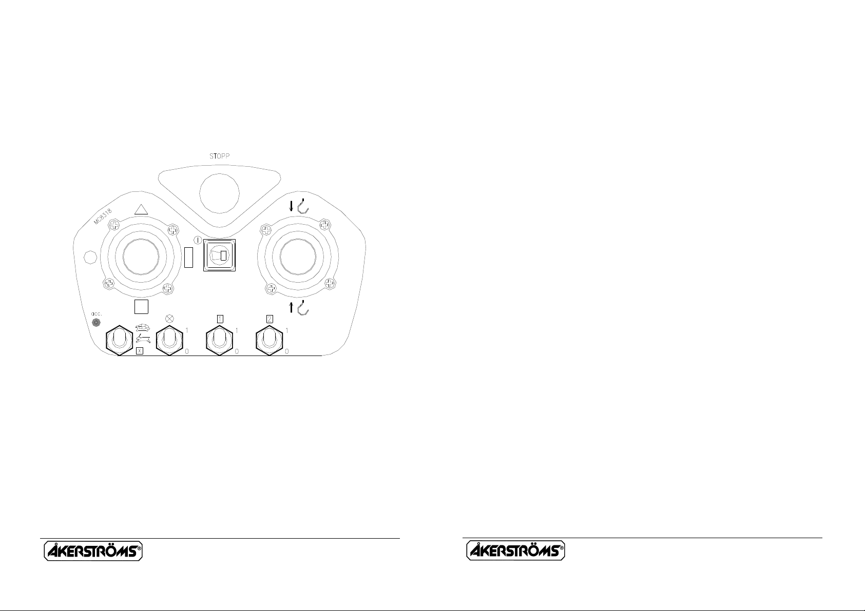
Variant 2
MANUAL MC8318 No. 923477-000 USA
Version: A0 Approved by: HH
Page. 3 (12)
TRANSMITTER ON
Pull out the STOP button and the transmitter will make a self-test
during 0,5 seconds. The operation indicator lamp (acc.) starts blinking
and the transmitter is on.
MAIN CONTACTOR ON
Then the transmitter is on press the signal button and this actuates the
Main Contactor in the receiver (the Main Contactor of the traverse
closes) and the traverse is ready for operation.
NORMAL RUN
The transmitter is designed with two manipulators:
One for Bridge/Trolley travel and the other for Hoist motions, each
direction being divided into 2 steps (a perceptible resistance)
facilitating run at a certain speed. The size and direction of the
manipulators deflections are equal to the speed and direction of the
objects motions. Bridge and Trolley can be run simultaneously in the
same manipulator. The motions stop when the manipulator is brought
to neutral, otherwise pull out the EMERGENCY STOP.
MANUAL MC8318 No. 923477-000 USA
Version: A0 Approved by: HH
Page. 4 (12)
Page 3

MICRO RUN (NOT SIMULTANEOUS)
X
X
X
Set the selector for MICRO / NORMAL / EXTRA in position MICRO.
The micro-run movements are only at lowest speed in micro-run mode
irrespective of the deflections of the manipulator. The other functions
are working just as in ordinary runs. The manipulated movements are
looped so that only one movement can be operated at a time.
EXTRA
The function is obtained immediately when the switch is actuated in
position .
Floodlight and Choise 1 and 2 only on variant 2 (See page 3).
FLOODLIGHT ⊗
The lights can be operated at any time after switching the Main
contactor ON, Light OFF must be set before Main Contactor OFF.
CHOISE 1, 2 or 1+2
Set the switch in desired position for switch-in of Choise 1, 2 or 1+2.
MANUAL MC8318 No. 923477-000 USA
Version: A0 Approved by: HH
Page. 5 (12)
SIGNAL
A signal can be emitted at any time during the run and is obtained as
long as the push button switch is depressed.
EMERGENCY STOP
Depress the STOP button for Emergency STOP.
AUTOMATIC SWITCH OFF
FUNCTION
The indicator lamp for operation goes out and the Main Contactor is
de-energized. For renewed activation of the Main contactor restart is
required, press the stop button, pull it out again and press the signal
button. Accumulator voltage below 6,1V also causes automatic switchoff.
MANUAL MC8318 No. 923477-000 USA
Version: A0 Approved by: HH
Page. 6 (12)
Page 4

TRANSMITTER OFF
MAIN CONTACTOR OFF
Depress the STOP button which switches off the transmitter. At the
same time the Main Contactor is deactivated (the Main Contactor of
the traverse cuts out). The operation indicator lamp goes out.
TRANSMITTER LED INDICATIONS
If the transmitter under start up or under drift detect a fault in any
selftests it will indicates with a continuously red light. After what the
transmitter closed down. If it indicates continuously yellow light when
you start up the transmitter it will be something fault with some of the
manipulators.
INDICATIONS EXPLANATIONS
Green flashing Drift
Yellow flashing Accumulatorvoltage low < 6,9 V
Yellow continuously Discharge accumulator voltage < 6.1 V
Red continuously Fault, see the productdescription
MANUAL MC8318 No. 923477-000 USA
Version: A0 Approved by: HH
Page. 7 (12)
RUN DOWN ACCUMULATOR
The transmitter is equipped with an indicator lamp (green and yellow)
for accumulator status. The lamp blinks green when the accumulator
voltage is normal(?7,2V), but starts to blink yellow when it falls
(<6,9V). When the indicator lamp has started blinking yellow the
transmitter can be operated approx. 10 min., before the voltage is so
low (<6,1V) that the transmitter switches off automatically. This is
indicated by the indicator lamp showing fixed yellow light.
The two last-mentioned statuses are also present at outlets in the
receiver.
MANUAL MC8318 No. 923477-000 USA
Version: A0 Approved by: HH
Page. 8 (12)
Page 5

!
CHARGING INSTRUCTIONS
! ! ! ! ! !
! !
∗ The accumulator has got power for 10 hours continuous operation.
∗ Charging time 2 hours (quick-charge) there upon automatically
changes to maintenance charging which does not need supervising.
∗ The charging device has LED indication for quick charge (fixed
red LED) or maintenance charge (flashing red LED).
∗ Take the accumulator out of the charger before the main-
connection is disconnect.
∗ A WELL MAINTAINED ACCUMULATOR IS NECESSARY
FOR FAULTLESS OPERATION.
∗ WATCH THE ACCUMULATED CHARGE AND CHARGING
CAREFULLY.
∗ THE ACCUMULATOR DID NOT BE CHARGED IF ITS
TEMPERATURE IS LOWER THAN +10°C OR HIGHER THAN
+35°C.
MANUAL MC8318 No. 923477-000 USA
Version: A0 Approved by: HH
Page. 9 (12)
INSTRUCTIONS FOR CRANE OPERATORS
These instructions have to be followed. Marked
1. Check that the radiotransmitter operates on the crane which you
are going to drive (ex. give a signal). Check the function of the
radiotransmitter.
2. Check that no unauthorized person is on or at the crane when
you start to drive it. The blocking device at entry of the crane
should be closed.
3. Check the position of the symbols for driving direction (cranetrolleytravel).
4. At the beginning of each shift the crane operator is to test brake,
limitswitches and emergency stop function.
5. The crane operator is when driving the crane to walk or stand at
a suitable distance from the crane hoist in order to have
adequate overview of the operation.
6. It is prohibited to move the crane load over oneself or
workmates. Signal in order to warn workmates.
7. Avoid driving into end stops since equipment and goods can be
damaged.
8. Check your own free passageway in order to avoid tripping over
material on the ground when you drive the crane Keep the
workplace in good order.
MANUAL MC8318 No. 923477-000 USA
Version: A0 Approved by: HH
Page. 10 (12)
Page 6

!
9. If you loose control of the crane movements, release the
! ! ! !
! !
manipulators to obtain the zero position in order to stop the
crane. If still it does not stop, actuate the STOP function.
10. Find out where the crane's main power disconnector is, in order
to be able to quickly switch off the power if required.
11. Never hand over the transmitter to anybody who has not
undergone training in radio-control crane operation.
12. After completed operation you should always switch the
transmitter off with STOP. Note! Do never put the transmitter
aside without switching the transmitter off sith STOP.
13. The main contactor of the crane is to be switched off after end
of working hours. The transmitter is then to be kept
inaccessible to unauthorized persons.
14. In case of faults or breakdowns in the radiocontrol equipment
the crane should permit operating from the cab or with
suspended operating gear. In such case first turn the switch
from radio operation to manual operation. Make certain how
this switch-over is to be made before you start driving any
individual crane.
15. Make sure that the receiver can not be activated when you
service the transmitter.
ALWAYS REPORT DEFECTS AND DEFICIENCIES TO
THE WORK MANAGEMENT.
MANUAL MC8318 No. 923477-000 USA
Version: A0 Approved by: HH
Page. 11 (12)
FCC Identifier OG4MC8318
This device complies with Part 15 of the FCC rules. Operation is
subject to the following two conditions: (1) This device may not cause
harmful interference, and (2) this device must accept any interference
received, including interference that may cause undesired operation.
Caution: Any changes or modifications not expressly approved by the
party responsible for compliance could void the user´s authority to
operate tne equipment.
MANUAL MC8318 No. 923477-000 USA
Version: A0 Approved by: HH
Page. 12 (12)
 Loading...