

Page 1
INSTALLATION INSTRUCTION REMOTUS 96XX 92 3161-000 Ver. C0 Page 1(3)
The following guide shall be used when installing Åkerströms Remotus CU9600 system, in
order to obtain a completely reliable operation. The installation shall be done by a competent
person.
1. MOUNTING
The permanent installation of the building must submit fuses which protect the equipment and
wiring from over-current and short-circuit. In detail the regular power supply of the equipment
and all relay-contacts must be fused.
All that fuses are used as separation devices. They must be easily accessible, must submit a
contact-gap of at least 3,0 mm and has to be placed in the line pole (L).
After the installation of the equipment, the installed cables must be bound together (e.g. by
using a cable binder) very close to the terminal blocks.
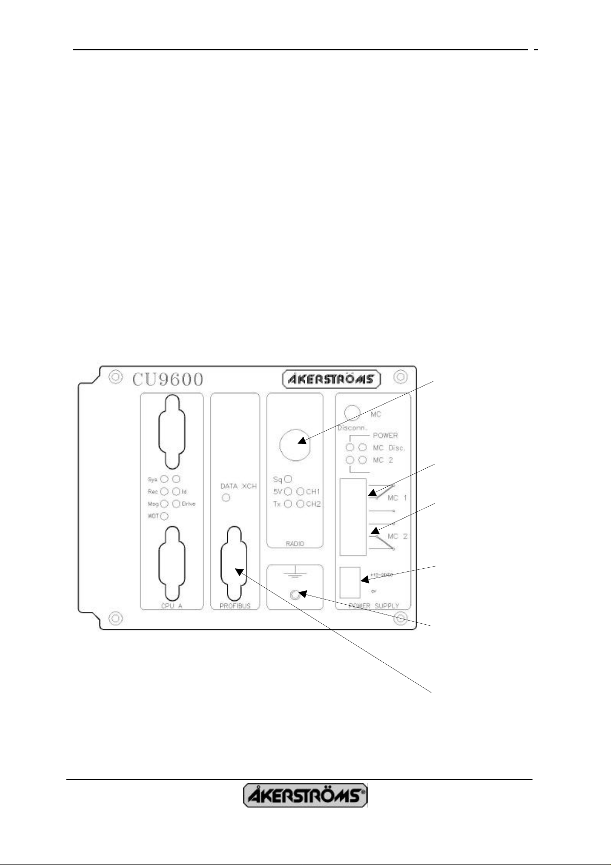
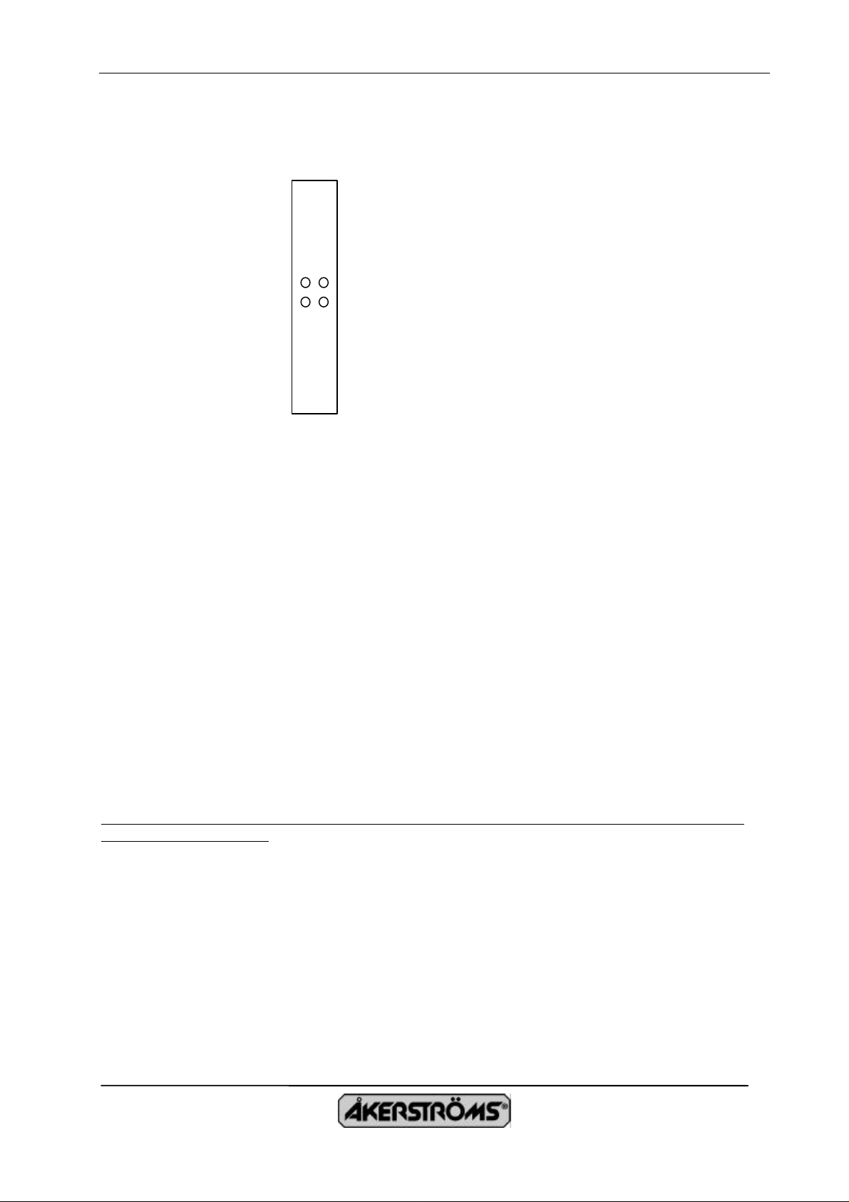
1.1 AERIAL PLACEMENT
The antenna for the receiver shall be placed as open as possible. Further information can be
found in drawing 90 8473-000.
Aerial connector
Connector for MC 1
Connector for MC 2
Connector for
Voltage supply
12-24VDC
Ground screw for
shield connection.
Connector for
Profibus DP.
020320
S-780 45 BJÖRBO, PHONE +46 241 – 250 00, FAX. +46 241 - 232 90
Page 2
INSTALLATION INSTRUCTION REMOTUS 96XX 92 3161-000 Ver. C0 Page 2(3)
Equipotientiaial
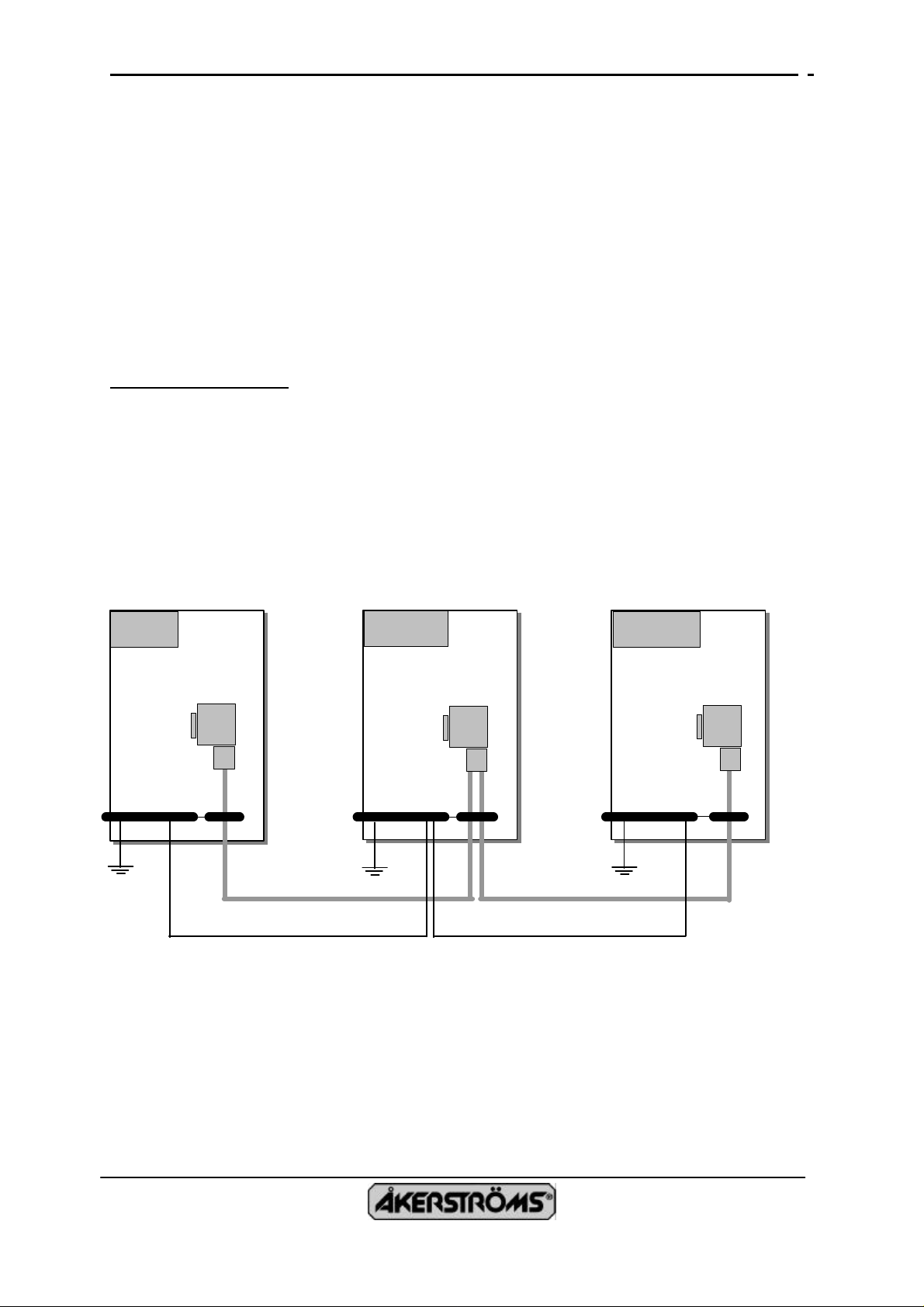
1.2 CONNECTION CABLE
Connection cable for power supply and main contactor (MC):
The cable shall have a CONCENTRIC SHIELD e.g. ÖLFLEX or similar and with a cable
area of 0,75-1mm². We recommend grounding the cable the same way as the cable for
Profibus (according to the figure below).
Voltage supply: 24 VDC (11-35 VDC)
Power consumption: Max 9W
Connection cable for Profibus:
We recommend the following cable type (Type A).
Type A is in particular suitable for high data rate (>500kbit/s).
Technical specification:
Impedance: 35 up to 165 Ohm at frequencies from 3 to 20MHz
Cable capacitance: <30pF by each meter
Cable area: >0,34mm², similar to AWG 22
Cable type: Twisted pair. 1x2 or 2x2 or 2x4 wires
Resistance: <110 Ohm by each km.
Signal attenuation: Max. 9dB over entire length
Shield: Double shield i.e. shield cover and shield foil
Max Bus length: 200 m at 1500 kbit/s, up to 1,2 km at 93,75 kbit/s
Place the cable for PROFIBUS separated from the cable for power supply.
Master
Equipotientiaial
rail
Data cable
Follower
rail
Equipotientiaial cable
Follower
Equipotientiaial
rail
Data cable
It is recommended to connect the shield on both sides low inductively with the protective
ground. Preferably the connection between shield and protective ground is made via the metal
cases. It should be noticed that this is not the optimal solution. In such a case it is better to
bare the cable shield at an appropriate point and to ground with a cable as short as possible to
the metallic structure of the cabinet. This could be achieved with a ground screw in front of
the CU96XX receiver.
If the machine parts NOT have the same ground potential, a equalization cable with great area
(e.g. 16mm²) most be connected between the parts and to the central protective ground.
020320
S-780 45 BJÖRBO, PHONE +46 241 – 250 00, FAX. +46 241 - 232 90
Page 3
INSTALLATION INSTRUCTION REMOTUS 96XX 92 3161-000 Ver. C0 Page 3(3)
Any modification to the equipment not expressively authorized by the party responsible for
compliance could void the user's authority to operate the equipment.
This device complies with Part 15 of the FCC rules. Operation is subject to the following two
conditions: (1) This device may not cause harmful interference, and (2) this device must accept any
interference received, including interference that may cause undesired operation.
FCC note:
The equipment user is required by the radio service rules to obtain a licence before operating the
equipment.
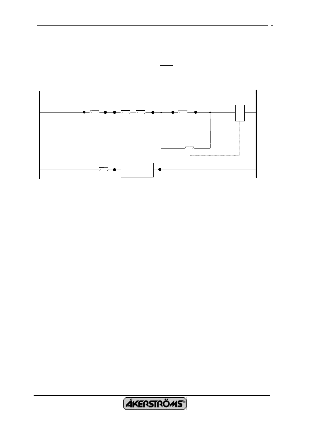
1.3 CONNECTION EXAMPLE FOR THE MAIN CONTACTOR
The maximum switching capacity of the relay contacts is 8A/250VAC at cosϕ=1.
Current loops that contains the relay contacts shall have a protection fuse rated 6 A.
1.3.1 Principal connection of the main contactor
Main contactor control from receiver
MC1 MC2
Possible ON-
function from PLC
Main contactor
Switch
Receiver
PROFIBUS DP
The receiver functions as a Profibus DP slave and have the identity 0x0765. This is fixed and
corresponds to the unit function as a Profibus DP slave.
• 16 byte consistent data in. The last byte is a checksum total for the 15 preceding bytes.
• 16 byte consistent data out.
On the Profibus board there are two rotary switches on which you can adjust the Profibus DB
slave address. The default address is 55.
A diskette with TYPE- and GSD-files are included with each delivery.
020320
S-780 45 BJÖRBO, PHONE +46 241 – 250 00, FAX. +46 241 - 232 90
Page 4
PRODUCT DESCRIPTION REMOTUS CU9600 92 3159-980 Rev. F Page 1(16)
Written by: Bengt Edström, Henrik Hedlund
Approved by: Tomas Bustad
Date: 02.10.24
R A D I O L I N K S Y S T E M
R E M O T U S C U 9 6 0 0
R E C E I V E R
for serial communication and fieldbuses
Datum: 02.10.24
780 45 BJÖRBO, TEL. + 46 241 25 000, TELEFAX. +46 241 232 90
Page 5

PRODUCT DESCRIPTION REMOTUS CU9600 92 3159-980 Rev. F Page 2(16)
CONTENTS
1. SPECIFICATION
2. CONSTRUCTION
3. FUNCTION DESCRIPTION
3.1 Security
3.1.1 DUAL channel approach.
3.1.2 Check of output devices.
3.1.3 Under voltage protection.
3.1.4 Over voltage protection.
3.1.5 Watch-dog
3.1.6 Test of all system code (FLASH EPROM).
3.1.7 Test of safety relevant code (FLASH EPROM).
3.1.8 Test of PLC-program (FLASH EPROM)
3.1.9 Test of data memory (RAM).
3.1.10 CPU-test
3.1.11 Software reset.
3.1.12 Main contactor
3.1.13 Emergency stop
3.1.14 Disturbed message
3.2 System configuration
3.2.1 Unit address
3.2.2 Selection of persistent functions
3.2.3 Manipulator decoding
3.2.4 Disconnect delay, brake lifter
3.2.5 Multi-operator and multi-crane operation
3.2.6 Settings for Profibus DP
3.3 Indications
3.4 Two-way communikation (duplex)
3.5 Communication with other equipment
3.6 Dipswitches
3.7 Test mode
3.7.1 Runtime information
3.8 Monitor
4. MESSAGE CHECK
5. CONNECTIONS
Appendix.
1 Description of the PLC system (90 8075-000).
2 Description of the MONITOR (90 8069-000).
Datum: 02.10.24
780 45 BJÖRBO, TEL. + 46 241 25 000, TELEFAX. +46 241 232 90
Page 6

PRODUCT DESCRIPTION REMOTUS CU9600 92 3159-980 Rev. F Page 3(16)
1. SPECIFICATION
o Part of the family REMOTUS 9000 and are therefore compatible with other units.
o Connects as a slave to fieldbus PROFIBUS DP. Max 16 byte out (120 functions
include checksum) and 16 byte in.
• Designed to fulfil security category 3 or category 5 (according to EN 954-1) by using
• way of double microprocessor-channels (redundancy).
o Double security circuits (3 MC-relays).
o Build-in powerful PLC-system.
o 14 bits address, which permits 16 384 different addresses.
o Selectable decoding of manipulators.
o Advanced multi-operator and multi-crane operator thanks to built-in PLC.
o One serial asynchronous communication channel for communication with scales,
position transmitters etc.
o Built-in monitor for test- and parameter settings.
o Indications for different functions in the system (status, outputs).
o Statistics functions programmable with built-in PLC.
o User-defined log function stores history.
Datum: 02.10.24
780 45 BJÖRBO, TEL. + 46 241 25 000, TELEFAX. +46 241 232 90
Page 7

PRODUCT DESCRIPTION REMOTUS CU9600 92 3159-980 Rev. F Page 4(16)
Radio frequency: 405-470 MHz. Other frequencies of request.
Channel separation: 25 kHz option 20 kHz or 12,5 kHz
Power output: 50/500 mW
Sensitivity (9600 baud): -100 dBm
Transfer speed: 9600 baud (4800 with 12,5 kHz)
Link turnaround time: 10 mS
Transmission principle: FSK
Radio fullfills: I-ETS 300 220
Fieldbus: PROFIBUS DP slave
ID = 765
Address = 55 (00-99)
16 (8) bytes consistent data input. The latest byte is a
checksum for the 15 previous.
16 (8) bytes consistent data output.
Extra communication channel: Serial asynchronous RS232/RS485
Voltage supply: 24 VDC (11-35 VDC)
Power consumption: Max 9 W
Working temperature: -25°C - +55°C
Storage temperature: -40°C - +85°C
MC-relays: 2 pc 250 VAC, 16 A resistive load
MC-relays fuses 2 pc 250 VAC, 10 A
Aluminium cabinet for mounting on a symmetric DIN rail EN50 022.
Dimensions: 125x135x135 (bxhxd)
Weight: 1 kg
Datum: 02.10.24
780 45 BJÖRBO, TEL. + 46 241 25 000, TELEFAX. +46 241 232 90
Page 8

PRODUCT DESCRIPTION REMOTUS CU9600 92 3159-980 Rev. F Page 5(16)
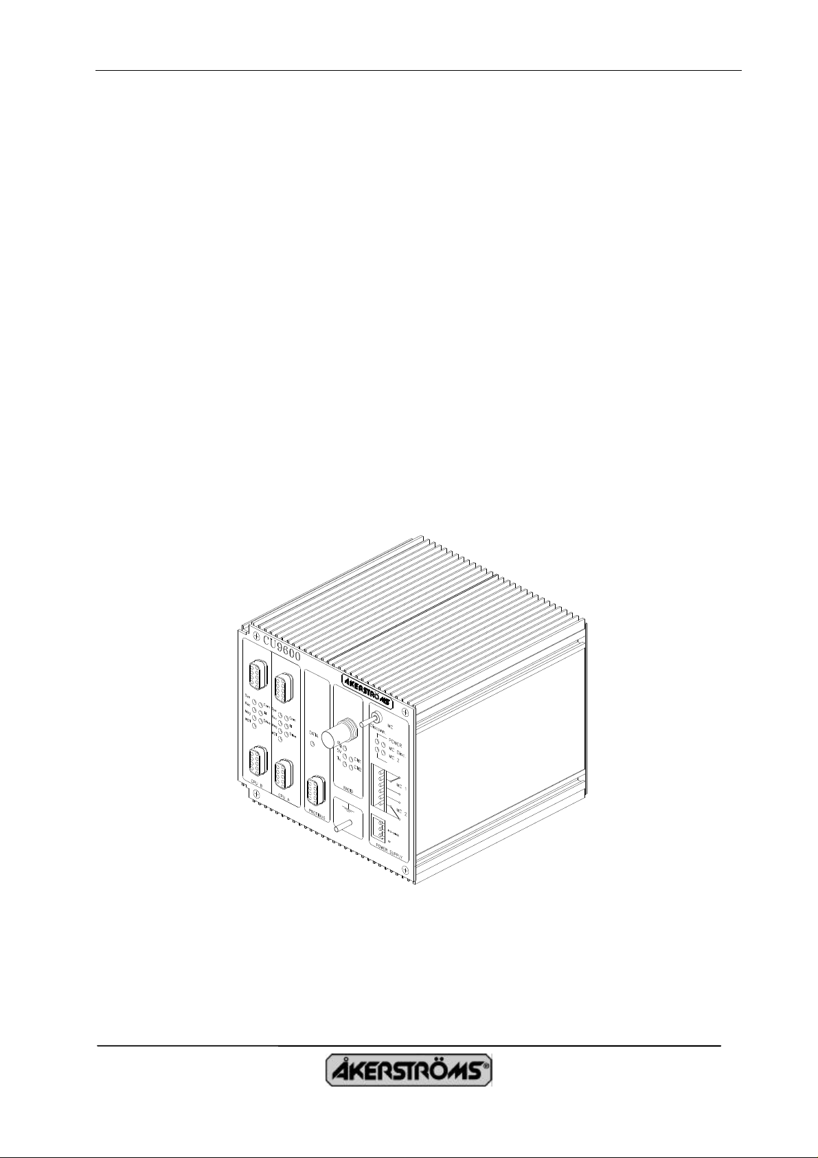
2. CONSTRUCTION
REMOTUS CU 9600 receiver consists of power supply-unit, RADIO/MODEM-unit, CPU-unit,
SP/HK-unit and fieldbus unit.
Outputs for functions as relays or analogue signals will be missing. Instead we transmit such
signals via a fieldbus to an available control unit (type PLC). A “fieldbus card“ which contents
the components which are specific for fieldbus Profibus DP, are mounting on the fieldbus-card.
For security reason there are relay outputs for emergency shutdown.
To reach the highest security level (5) the CPU-unit must be mounting with two identically
CPU:s with data/program- memory, indications, voltage supply etc.
The standard cabinet is of “aluminium“ and designed for mounting on DIN-rail.
The receiver is designed to be mounted together with a PLC in the same cabinet suitable for the
present environment.
Dipswitches
RS232
RADIO
CPU-A
Fieldbus
CPU-B
Power supply
MC1
MC2
24 V
Datum: 02.10.24
780 45 BJÖRBO, TEL. + 46 241 25 000, TELEFAX. +46 241 232 90
Page 9

PRODUCT DESCRIPTION REMOTUS CU9600 92 3159-980 Rev. F Page 6(16)
3. FUNCTIONAL DESCRIPTION
The REMOTUS CU 9600 receiver has been designed to be a very compact unit.
The receiver is fully compatible with REMOTUS 9000 family. It is thus possible to use any
REMOTUS 9000 transmitter with a REMOTUS CU 9600 receiver. Functional flexibility is
obtained with a built-in PLC system and fieldbus connection to superior PLC.
The software consists of four main parts:
Radio communications module:
This receives and checks messages from the transmitter. It also executes the safety checks. The
logic for closing and opening the main contactor and decoding is handled by this module. A
number of variants are programmed in for this purpose, which are chosen during "configuration".
PLC module:
This module is functionally positioned between the above module and the outputs. The functions
can therefore be "processed" before they are outputted. The processing can consist of placing
functions on certain outputs, delaying, combining, sequencing, duplicating etc. Micro-mode can
be programmed in the PLC module. PLC programs are written separately on an ordinary
personal computer. The result is downloaded into the onboard FLASH-EPROM.
Fieldbus-module:
This module handles the communication with the fieldbus. Output from the PLC-module
transmits out to the control module for the fieldbus. Data from the fieldbus takes also in and
transmits as in data to the PLC-module.
Monitor module:
This module can be used to read and write anywhere in the PLC memory. This is particularly
useful for testing PLC programs and for fault tracing. The monitor is also used to set the serial
communication channel (see section 3.7) and to handle logging (see section 3.6) and statistic (see
section 3.5). For logging, it is necessary to select which variables are to be logged. To use the
monitor, it is first necessary to give a "password". A simple hand terminal is adequate for
communication with the monitor. It is connected to the front of the CPU-board. If only one CPUboard is installed the prompt on the monitor is “R9000>”.If two CPU-board are installed the
prompt on the monitor is "R9000A>" for CPU:A and ”R9000B>” for CPU:B.
Datum: 02.10.24
780 45 BJÖRBO, TEL. + 46 241 25 000, TELEFAX. +46 241 232 90
Page 10

PRODUCT DESCRIPTION REMOTUS CU9600 92 3159-980 Rev. F Page 7(16)
3.1 Safety
The safety level of this receiver is normally category 3. Category 5 is available during design
with dual CPU-board which works in parallel channels design and a large number of safety tests.
3.1.1 DUAL channel approach.
With only one CPU-board (category 3) the MC-relays activates via two separate control signals.
With two CPU-boards (category 5) the MC relays activates differentiate of both
microprocessors-channels i.e. both must be agreed for activate the MC-relays. Output data from
the both channels are compared of respective CPU before it transmits out via the fieldbus.
3.1.2 Check of output devices.
Test of driver outputs:
One side of the relay-coil is driven by cpu-A through a positive driver (source) and the other side
is driven by cpu-B through a negative driver (sink). When the main contactor is deactivated all
source drivers is monitored for not being in high state by cpu-A and all sink drivers is monitored
for not being in low state by cpu-B. In case of failure the main contactor is prevented to be
activated by the respective cpu. The respective cpu:s also clears the outputs which transmits to
the fieldbus.
3.1.3 Under voltage protection.
This consists of one device for each channel. The trip voltage is 4,65 V.
o Fault -> hardware reset.
3.1.4 Over voltage protection.
This consists of one device (MAX921) for each channel. The trip voltage is set to 5,5 V.
o Fault -> hardware reset.
3.1.5 Watch-dog.
A watchdog timer is used to monitor microprocessor function. This watchdog must be constantly
"patted" or it will "bite". "Patting" is the task of the microprocessor, which sends pulses regularly
to the watchdog. If the time between pulses is too long, the dog will "bite", which results in a
hardware reset.
There are one device for each CPU-board. It monitors a separate signal from the CPU.
o Fault -> hardware reset (indicated on a led).
The watch-dog is only maintained if an exact number of program-modules has been executed
during a ”software-cycle”.
The signal feeding the respective watch-dog is also fed to the opposite cpu which enables the
cpu:s to monitor each other. This is done all the time the receiver is running.
o Fault after the fault-tolerance-time -> All outputs cleared and main contactor off.
CPU-A
CPU-A
CPU-B
WDT-A
WDT-A
WDT-B
1 CPU-board 2 CPU-board
Datum: 02.10.24
780 45 BJÖRBO, TEL. + 46 241 25 000, TELEFAX. +46 241 232 90
Page 11

PRODUCT DESCRIPTION REMOTUS CU9600 92 3159-980 Rev. F Page 8(16)
3.1.6 Test of all system code (FLASH EPROM).
The test is done after power up and consecutively and consists of a CRC8-test comparing the
result with a correct value stored in the EPROM. The test which is done consecutively takes
about 600 seconds.
o Fault -> hardware reset and indication on leds.
3.1.7 Test of safety relevant code (FLASH EPROM).
The safety code-segment is tested approx. every 3 seconds. The test consists of a CRC8-test
comparing the result with a correct value stored in the EPROM.
o Fault -> software reset and indication on leds.
3.1.8 Test of PLC-program (FLASH EPROM).
The plc-program code-segment is tested initially and approx. every 60 seconds. The test consists
of a CRC8-test comparing the result with a correct value stored in the EPROM.
o Fault -> All outputs cleared and the main contactor off.
3.1.9 Test of data memory (RAM).
The data memory consists of two separate RAM-memories which one ”mirror” the other.
Data writes to both memories. At reading the both RAM-memories contents will be compared by
a comparator.
If differents detects -> the comparator-unit indicates the error to the CPU via an input port and
after a special time it makes a software reset.
At reset:
o All used RAM-memory are tested by a ”walking bit” and initialised to zero.
o The comparator for the both ram-memories are tested.
Error at some of the above tests -> the error indicates and after a special time it makes a software
reset.
3.1.10 CPU-test.
This test is implicit indirect as a natural part in the software and is here furthermore increase with
a separate testmodule for testing certain instructions.
o Fault -> indirect hardware reset (the software will hang and the watchdog will reset the CPU).
3.1.11 Software reset.
Software reset initiates the ports to safe levels and clears the outputs. Then the maintaining of the
watchdog stops which should reset the cpu.
If no reset occur the software will hang in this position.
Datum: 02.10.24
780 45 BJÖRBO, TEL. + 46 241 25 000, TELEFAX. +46 241 232 90
Page 12

PRODUCT DESCRIPTION REMOTUS CU9600 92 3159-980 Rev. F Page 9(16)
3.1.12 Main contactor
The function of the main contactor plays a central role in the control of a crane. When the main
contactor is open, all control of the crane is impossible.
The main contactor is controlled via double relays, which activates through both microprocessors
in differential connection.
To activate the main contactor following rules must be fulfilled:
o At least one correct message received within the "fault tolerance time"
o No manipulator (movement) must be active.
o No "emergency stop message" from the transmitter.
o No interlock from PLC-program.
o No software test errors. (Incl. Watchdog-test of opposite cpu)
o No hardware test errors.
o No MC-driver error (driver check).
o Communikation with the fieldbus ok.
The main contactor will be deactivated if anything from the following list occur:
o "Emergency stop message" from the transmitter.
o No errorfree message received from the transmitter within the "fault tolerance time".
o Stop-command from the PLC-program.
o Missmatch between manipulator (movement) -value and centerposition information from
the transmitter during fault-tolerance-time.
o Software test errors. (Incl. Watchdog-test of opposite cpu)
o Hardware test errors.
o Communication error with fieldbus.
To be able to test the system with no fieldbus available there is a toggle switch mounted on the
SP/HK-board. This prohibits the ”security relays” to be activated and at the same time enables
the system to enter ”drift-mode” with no fieldbus present.
3.1.13 Emergency stop
An emergency stop message is sent to the receiver if the emergency stop on the transmitter has
been pushed in or when the voltage in the storage accumulator is too low or when tests on the
transmitter gives error..
The following occurs when an emergency stop message has been received:
o The main contactor is deactivated.
o All functions that are not supposed to be persistent are cleared (see 3.2.2).
3.1.14 Disturbed messages
If the message has been disturbed for more than the ”fault tolerance time", which is 0.5 seconds,
the same steps are taken as in the event of an emergency stop message.
Datum: 02.10.24
780 45 BJÖRBO, TEL. + 46 241 25 000, TELEFAX. +46 241 232 90
Page 13

PRODUCT DESCRIPTION REMOTUS CU9600 92 3159-980 Rev. F Page 10(16)
3.2 System configuration
As a rule, each installation requires its own special customized solution. The intended method
for accomplishing this in REMOTUS CU9600 is via the software (program) in the CPU unit. A
number of variants are preprogrammed in the program and can be selected at system delivery.
Variants are selected by the modification of certain fixed points in a master program. This is
done in the PLC program. Functions can also be combined, sequenced, time-delayed, moved,
duplicated etc. with the PLC module.
Hereinafter we will call this procedure "configuration". The advantages of having options easily
accessible in the software are that it eliminates the necessity of having to administer a large
number of different systems programs, the costs are reduced and the delivery time can be
shortened.
3.2.1 Unit address
The unit address of the receiver is determined in "configuration".
3.2.2 Selection of persistent functions
Certain fixed functions, headlights etc, should normally not be turned off simply because
reception has been disturbed for a time. The program is prepared for simple selection of these
functions during "configuration".
3.2.3 Manipulator decoding
Different decodings require different numbers of functions. With 4-step decoding, six functions
are required per travel movement. These functions cover the following: 2nd, 3rd and 4th step
plus forward, reverse and brake lifter.
Decoding of the manipulators can be done in several ways. A number of variants are
preprogrammed and can be selected during "configuration".
Note that each travel movement can have different decoding.
Decoding options:
o Direct (grey code or functions)
o 4-step
o 5-step and 4-step
o 16-step and 4-step
o Binary and 4-step
o Analog and 4-step (Not relevant in this receiver)
3.2.4 Disconnect delay, brake lifter
The brake lifter is on when the manipulator is activated. Furthermore it is disconnect-delayed 1
second (so that the manipulator arm can pass the zero position). The brake lifter's disconnect
time can be selected during configuration. This time is the same for all travel movements, but it
can be varied through a PLC program.
Datum: 02.10.24
780 45 BJÖRBO, TEL. + 46 241 25 000, TELEFAX. +46 241 232 90
Page 14

PRODUCT DESCRIPTION REMOTUS CU9600 92 3159-980 Rev. F Page 11(16)
3.2.5 Multi-operator and multi-crane operation
Multi-operator and multi-crane operation are controlled via the PLC program:
Base functions that must be programmed are:
o frequency switching rate.
o conditions for locking to a certain frequency (operator).
o conditions for presentation.
o conditions for what happens in case of incorrect addressing (subaddress)
In this method any functions can be utilized for the subaddress. The presentation code can also
be determined freely.
Note that in parallel with the above methods, verification of the messages and time monitoring
also naturally functions, which can thus lead to emergency stop of the crane.
3.2.6 Settings for the Profibus DP
o The unit functions as a Profibus DP slave and has the identity 765H. This is fixed and
corresponds to the unit function as a Profibus DP slave.
o On the Profibus board there are two rotary switches on which you can adjust the Profibus
address. The default address is 55 (see section 3.8).
o As a Profibus DP slave the unit has the following configuration:
Base configuration 16 bytes consistent data input and 16 bytes consistent data output.
Automatically it can adjustment to 8 bytes consistent data input and 8 bytes consistent data
output.
If the configuration is 16 bytes consistent data input the byte 16 is a checksum for the
previous 1-15. It consist of an ”exclusive or” of byte 1-15.
If the configuration is 8 bytes consistent data input the byte 8 is a checksum for the
previous 1-7. It consist of an ”exklusive or” of byte 1-7.
Datum: 02.10.24
780 45 BJÖRBO, TEL. + 46 241 25 000, TELEFAX. +46 241 232 90
Page 15

PRODUCT DESCRIPTION REMOTUS CU9600 92 3159-980 Rev. F Page 12(16)
1:SQ
5:Tx
3.3 Indications
Observe! If it is two cpu:s the indications are double.
On CPU-board:
Normal indications:
1. System error.
2. Error in the communikation between CPU:A and CPU:B.
3. Indication of reception error. Lit after 400 ms when no valid message is received.
4. Indicating address error (ID). Wrong ID received.
5. Indicating correct received message. ”Message OK”.
6. Indicating drift-mode. Lights when MC is activated.
7. Indicating Watchdog-timer. It should always flash.
Fatal error indications:
1 and 3 lit: Ram error.
1 and 4 lit: Flash Eprom error.
On radio-board:
1. Indicating of radiosignal (squelch). Better than -90 dBm.
3. Indicating + 5V is ok on the board.
4. Indicating channel 1.
5. Indicating message to the transmitter (duplex).
6. Indicating channel 2.
On Profibus-board:
One led indicating communication with the fieldbus. It should lit at operation.
7:Sys error
1:SYS ERR
5:Rec. Error
3:REC. ERR
3:Korr. msg
5:MSG OK
1:WDT
7:WDT
3:+ 5V
2:Com. error
2:COM. ERR
6:ID error
4:ID ERR
4:Mode
6:DRIFT
4:CH 1
6:CH 2
Datum: 02.10.24
780 45 BJÖRBO, TEL. + 46 241 25 000, TELEFAX. +46 241 232 90
Page 16
PRODUCT DESCRIPTION REMOTUS CU9600 92 3159-980 Rev. F Page 13(16)
On SP/HK-board:
1. Indicating 7,5V system voltage (green).
2. Indicating the MC-switch (yellow). Lights if MC-relays are disabled.
3. Indicating MC-relay 1 and 3 (green).
4. Indicating MC-relay 2 (green).
1:7,5 VDC
3:MC-relay 1,3
2:MC disabled
4:MC-relay 2
3.4 Two-way communication (duplex)
By two-way communication is meant that the receiver can send information back to the
"transmitter" (MC 9x00). The information that is sent back may be weight, position, indica-tion
of overload etc. Several values can be shown on the transmitter's display by introducing a
selector switch. What is to be sent back is determined by a PLC program.
In order for two-way communication to be possible, the RADIO-board must be equipped with a
radio transmitter and the MC 9x00 with a radio receiver and a display unit.
3.5 Communication with other equipment
REMOTUS CU 9600 has one serial asynchronous communication channel for communication
with other equipment. Common communication units are scales, position transmitters,
DIRACOM systems etc. The values from these units are available for further processing in a
PLC program. Results can be shown on the display in the control unit with two-way
transmission. Setting of communication parameters and protocol can be done with the aid of the
built-in monitor. The settings are stored in an EEPROM, which does not require any battery
backup. The electrical signal interface is RS232/RS485.
The communication port require only one setting (via the monitor) and a possible addition in the
PLC program.
(Due to safety liability only PCs / terminals with power supplies approved in accordance with
EN 69050 may be used.)
3.6 Dipswitches
On the CPU-board there are 6 dipswitches:
SW1. ON :RS232. OFF:RS485 for extra communication port.
SW2. OFF:RS232. ON :RS485 for extra communication port.
SW3. Not used, have to be in OFF position.
SW4. Test of watchdog-timer (on).
SW5. ON if only one CPU-board in the system. OFF if it is two CPU-board in the system.
SW6. For lithium-battery (on).
På fältbusskortet finns två vridomkopplare:
SW5 och SW6 används för att ställa in adressen i profibussnätet (00-99). Default 55.
Datum: 02.10.24
780 45 BJÖRBO, TEL. + 46 241 25 000, TELEFAX. +46 241 232 90
Page 17

PRODUCT DESCRIPTION REMOTUS CU9600 92 3159-980 Rev. F Page 14(16)
3.7 Test mode
3.7.1 Runtime information
If a VT100 terminal is connected to one of the monitor connectors the following information will
appear at certain instances: (9600 baud 8N1).
The following information is available online and helps finding out why the main contactor fails
to activate. Note that this information appear spontaneous when you are not logged in to the
monitor. When logged in the same information is available by the command ”WHY”.
Normal indication the main contactor is activated.
"No interlocking!"
Indicates that there is an error in the other cpu.
"The other cpu is not responding."
Sometimes it is desired to only allow the main contactor (MC_on) if the radiosignal is strong
enough. This means that the operator must be close to the crane. If the squelch value is to low the
following information will appear.
”Squelch interlock.”
PLC-program memory error
"Error in PLC-program checksum."
The receiver cannot receive a correct message.
"Timeout or error in radiomessage."
It takes 3 successive errorfree messages to enter RUN-mode.
"More errorfree messages required."
The operator has touched some manipulator and at the same time tried to enter RUN-mode. The
activation of the main contactor is interlocked by an active manipulator.
"Some manipulator is active."
There might be some interlocking from the PLC-program. For instance the operator must press
the SIGNAL-button in order to activate the main contactor.
"Interlocking from PLC-program."
Datum: 02.10.24
780 45 BJÖRBO, TEL. + 46 241 25 000, TELEFAX. +46 241 232 90
Page 18

PRODUCT DESCRIPTION REMOTUS CU9600 92 3159-980 Rev. F Page 15(16)
3.8 Monitor.
There are one connector for monitor on every CPU-card.
When logging into the monitor (password=23250) the following menu appears:
(9600 baud 8N1).
CU9600 919xxx.100
ID=1234
R9000A> ;for cpuA
R9000B> ;for cpuB
In the monitor several useful commands can be used:
• Command WHY
is used to find out why the main contactor fails to activate.
Se also section ”3.7.1 Runtime information”.
In addition to this the following appear:
”Timeout or error in radiomessage. -nndBm Received ID = xxxxx”
where nndBm -> the radio signal strenght in dBm
Received ID= xxxxx -> the ID decoded by the receiver
• Command ERR
gives some information of detected errors since last power off.
EPROM-error =x test 3.1.7
RAM-error =x test 3.1.9
DRIVERx-error =x test 3.1.2
WDTx-error =x test 3.1.5
PLC-error =x test 3.1.8
x is not ”0” if an error is detected. Note that at the same time this command is entered the
information is cleared.
• Command LOGG
There are logging facilities built in. The following text appears:
Enter the functions that shall be logged.
MC and DIRECTIONS are always logged!
15 more functions can be logged.
Enter as: a no.
Where a=X, L or Y and no.=0-255
ESC quits directly.
Only ENTER doesnot change numbers.
01: =
To fill in this, information must be collected from the customized PLC-program that is
used.
This logg can store 1500 changes in the logged signal which will typically take more than one hour.
Datum: 02.10.24
780 45 BJÖRBO, TEL. + 46 241 25 000, TELEFAX. +46 241 232 90
Page 19

PRODUCT DESCRIPTION REMOTUS CU9600 92 3159-980 Rev. F Page 16(16)
• Command LOGGVIS
Is used to look at the logged result.
H X X X X X X X X Y L L
K 4 5 1 1 1 1 2 2 0 2 0
1 0 1 6 7 2 3 0 4 1
0 8 2
. . . . . . . . . . 1 1 1 1 1 1 1 . 1 1 1 1 1 1 08-12 08:40,58
1 . . . . . . . . . 1 1 1 1 1 1 1 . 1 1 1 1 1 1 08-12 08:40,59
1 . 1 . . . . . . . 1 1 1 1 1 1 1 . 1 1 1 1 1 1 08-12 08:40,59
1 . 1 . . . . . . . 1 1 1 1 1 1 1 . 1 1 1 1 1 1 08-12 08:40,59
1 . . . 1 . . . . . 1 1 1 1 1 1 1 . 1 1 1 1 1 1 08-12 08:41,00
1 . . . . . . . . . 1 1 1 1 1 1 1 . 1 1 1 1 1 1 08-12 08:41,04
Date and time is showed at the right. The time resolution is 1 second.
Command VX
Are used to show inputs to the receiver.
Command VY
Are used to show outputs from the receiver.
4. MESSAGE CHECK
It is of extra ordinary importance that no incorrect message is conceived as correct of the
receiver. Consequently, control information is added to the message to enable an interpretation
whether the message is incorrect or correct.
CRC8 is used as a checksum, which gives a hammingdistance of 4. In the receiver faults in start
and stop-bits are also detected. The checksum consists of one byte.
In REMOTUS CU9600, with 46 functions from the transmitter, a normally message takes 15 ms
to transmit at 9600 baud.
5. CONNECTIONS
o For voltage supply: Screw-connector; 24 VDC; 10 VA
o For MC-connector: Screw connector; 250 VAC; 10 A
o For extra communication port: 9-pol D-sub; Serial asynchronous RS232/
o For fieldbus: 9-pol Dsub; RS485 for Profibus DP
o For radio antenna: BNC
Datum: 02.10.24
780 45 BJÖRBO, TEL. + 46 241 25 000, TELEFAX. +46 241 232 90
 Loading...