

Page 1
DRIVING INSTRUCTION
REMOTUS BC8518
928754-000 USA
MANUAL BC8518 No. 928754-000 USA
Version: A0 Approved by: HH
Page 1 (12)
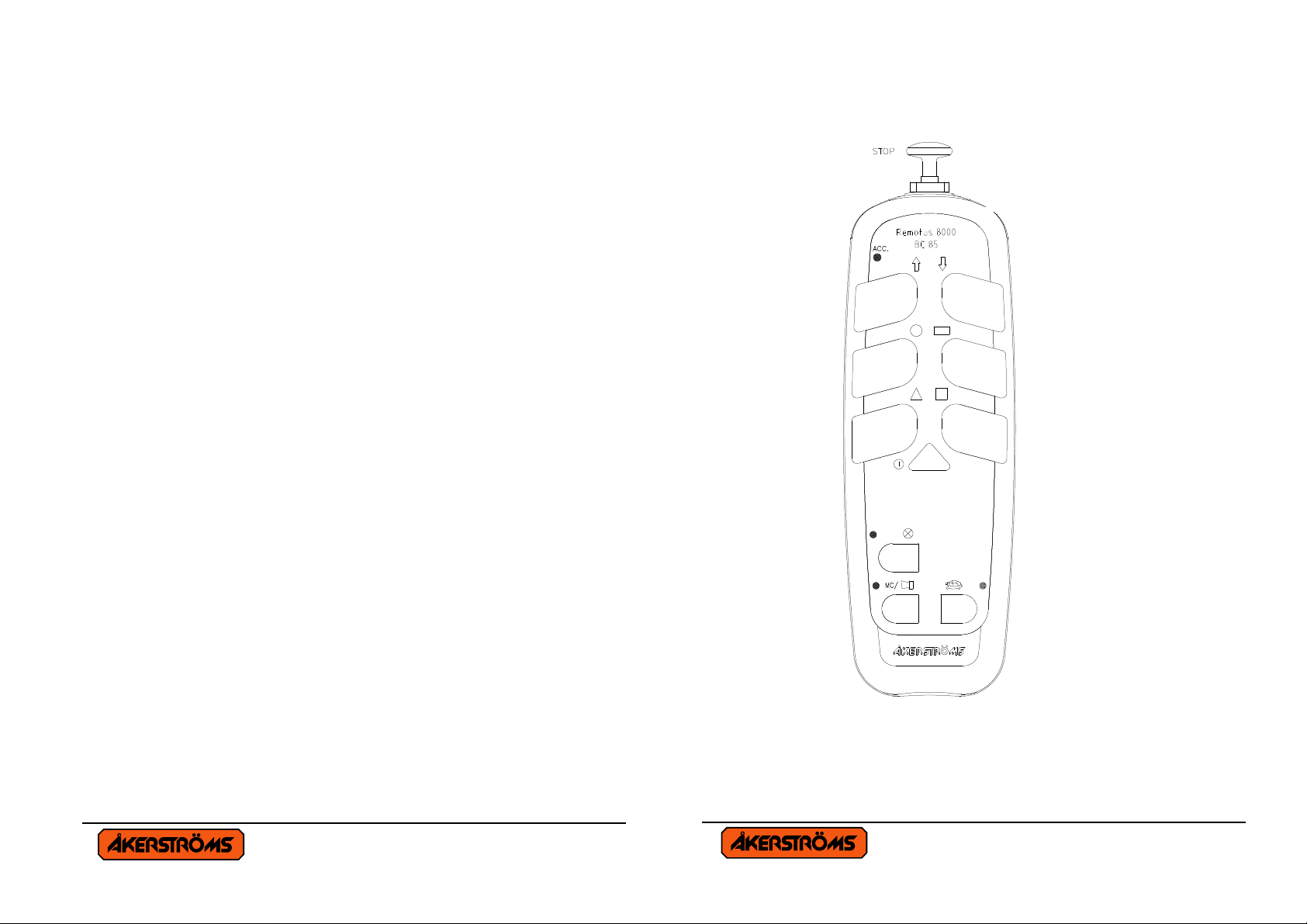
Variant 1.
MANUAL BC8518 No. 928754-000 USA
Version: A0 Approved by: HH
Page 2 (12)
Page 2

Variant 2.
MANUAL BC8518 No. 928754-000 USA
Version: A0 Approved by: HH
Page 3 (12)
TRANSMITTER ON
Pull out the stop button and the transmitter is switched on. The
operation indicator lamp (ACC.) starts blinking and the transmitter
is on.
ELECTRONIC LOCK
If the operating indication LED is red, the electronic lock is
activated. Contact the works manager or see the Installations
manual.
MAIN CONTACTOR ON
Then the transmitter is on, press the signal button and this actuates
the Main Contactor in the receiver, and it is ready for operation.
NORMAL RUN
The transmitter is designed with two pushbuttons for HOIST
Up / Down, two for BRIDGE Forward / Backward and two for
TROLLEY Left / Right. Each button is divided into 2 steps
(a perceptible resistance) which facilitates the running at a certain
speed. The first speed is obtained when the pushbutton is half
compressed and the second speed is obtained when the pushbutton is
totally compressed.
All the motions can be run simultaneously and the motions stop
when the pushbutton is released, otherwise make an EMERGENCY
STOP.
MANUAL BC8518 No. 928754-000 USA
Version: A0 Approved by: HH
Page 4 (12)
Page 3

MICRO RUN
X X
Push in the button for MICRO and the diode lamp for micro lights.
The micro-run movements are only at lowest speed in micro-run
mode irrespective of the compression of the pushbuttons. The
buttons are looped so that only one movement can be operated at a
time. The other functions are working as in ordinary runs.
FLOODLIGHT ⊗
The lights can be operated at any time after switching the Main
contactor ON, Light OFF must be set before Main Contactor OFF.
Otherwise the function remains. A diodlamp indicate that the light is
on.
One extra function and Choice 1 and 2, works only on variant 2.
(See page 3)
EXTRA
Function is obtained immediately when the switch is actuated in
position .
CHOICE 1, 2 or 1+2
Push the button for 1 and/or 2, and the diode lamps indicate the
selection.
MANUAL BC8518 No. 928754-000 USA
Version: A0 Approved by: HH
Page 5 (12)
SIGNAL
A signal can be emitted at any time during the run and is obtained as
long as the push button switch is depressed.
EMERGENCY STOP
Depress the STOP button for Emergency STOP.
TRANSMITTER OFF
MAIN CONTACTOR OFF
Depress the triangular button for about 2 seconds, until the
indication for operation goes out, which switches off the transmitter.
At the same time the Main Contactor in the receiver is deactivated.
AUTOMATIC SWITCH OFF
FUNCTION
The indicator lamp for operation goes out and the Main Contactor is
de-energized. For renewed activation of the Main contactor restart is
required, press the stop button, pull it out again and press the signal
button. Accumulator voltage below 5,7V also causes automatic
switch-off.
MANUAL BC8518 No. 928754-000 USA
Version: A0 Approved by: HH
Page 6 (12)
Page 4

TRANSMITTER LED INDICATIONS
If the transmitter under start up or under operating detect a fault in
any self-tests it will indicate with a continuously red light. After that
the transmitter closes down. If it indicates continuously yellow light
when you start up the transmitter, at least one of the pushbuttons is
activated.
INDICATIONS EXPLANATIONS
Green flashing Operating
Yellow flashing Battery voltage low < 6,3 V
Yellow continuously Discharge battery voltage < 5,7 V
Red continuously,
at start
Red continuously,
Electronic lock, see the Installation
manual
Fault, see the Installation manual
at operating
DISCHARGED BATTERY
The transmitter is equipped with an indicator lamp for battery status.
The lamp blinks slowly green when the battery voltage is normal
(7,4V), but starts to blink rapidly yellow, when it falls (6,3V). When
the indicator lamp has started blinking rapidly yellow, the
transmitter can be operated for approx 10 min. before the voltage is
so low (5,7V) that the transmitter switches off automatically. The
indicator lamp showing fixed light indicates this.
MANUAL BC8518 No. 928754-000 USA
Version: A0 Approved by: HH
Page 7 (12)
CHARGING INSTRUCTIONS
• The battery has got power for 12 hours continuous operation.
• Charging time is 2 hours.
230V AC CHARGING DEVICE
• Manufacture ANSMANN
The charging device has a green LED, shows that the charger is
connected to the main, and a red LED who indicates:
Continuously indication Charging
Flashing indication The battery is wrong or not connected
No indication Full charged battery
• Manufacture MASCOT
Do not connect the charger to the mains before it is connected to
the battery. The charging device has a LED who indicates:
Orange indication Quick charge
Yellow indication Maintenance charge
Green indication Full charged battery
DC CHARGING DEVICE
• The charging device has a fixed GREEN indication for quick.
charge. When the battery is charged the indication switches off.
Still a certain maintenance charge is going on.
• NOTE! If the indication not light when the battery is placed in
the charger, the remaining capacity in the battery is to high to
enable quick charge.
• Take the battery out of the charger before the main-connection is
disconnected.
MANUAL BC8518 No. 928754-000 USA
Version: A0 Approved by: HH
Page 8 (12)
Page 5

• A WELL MAINTAINED BATTERY IS NECESSARY FOR
!
! ! ! ! ! !
! !
FAULTLESS OPERATION
• CHARGE THE BATTERY AS SOON AS THERE IS
POSSIBILITY.
• THE BATTERY MUST NOT BE CHARGED IF THE
TEMPERATURE IS LOWER THAN +10°C OR HIGHER
THAN +35°C.
• Only use by supplier approved charger.
DISCHARGED BATTERY.
A Li-Ion battery is environment conformed, but as usually, all
batteries shall be handed back for recycling. When the battery will be
changed, the used Li-Ion-battery shall be returned to the distributor,
where a new battery is to be bought. Just to make sure that a proper
battery will be required. An alternative is to directly dispose of the
battery for recycling.
Old batteries shall be returned for recycling.
MANUAL BC8518 No. 928754-000 USA
Version: A0 Approved by: HH
Page 9 (12)
INSTRUCTIONS FOR CRANE OPERATORS
These instructions have to be followed. Marked
1. Check that the radiotransmitter operates on the crane,
which you are going to drive (ex. give a signal). Check the
function of the radiotransmitter.
2. Check that no unauthorized person is on or at the crane
when you start to drive it. The blocking device at entry of
the crane should be closed.
3. Check the position of the symbols for driving direction
(crane-trolley travel).
4. At the beginning of each shift the crane operator is to test
brake, limitswitches and emergency stop function as well
as the STOP button on the transmitter.
5. The crane operator is when driving the crane to walk or
stand at a suitable distance from the crane hoist in order to
have adequate overview of the operation.
6. It is prohibited to move the crane load over oneself or
workmates. Signal in order to warn workmates.
7. Avoid driving into end stops since equipment and goods
can be damaged.
8. Check your own free passageway in order to avoid tripping
over material on the ground when you drive the crane Keep
the workplace in good order.
MANUAL BC8518 No. 928754-000 USA
Version: A0 Approved by: HH
Page 10 (12)
Page 6

! !
9. If you loose control of the crane movements, release the
! !
! !
!
pushbuttons in order to stop the crane. If still it does not
stop, actuate the STOP function.
10. Find out where the crane's main power disconnection is in
order to be able to quickly switch off if required.
11. Never hand over the transmitter to anybody who has not
undergone training in radio-control crane operation.
12. After completed operation you should always switch the
transmitter off with STOP. Note! Do never put the
transmitter aside without switching the transmitter off with
STOP.
13. The main contactor of the crane is to be switched off after
end of working hours. The transmitter is then to be kept
inaccessible to unauthorized persons.
14. In case of faults or breakdowns in the radiocontrol
equipment the crane should permit operating from the cab
or with suspended operating gear. In such case first turn the
switch from radio operation to manual operation. Make
certain how this switch-over is to be made before you start
driving any individual crane.
15. Make sure that the receiver cannot be activated when you
service the transmitter.
ALWAYS REPORT DEFECTS AND DEFICIENCIES TO
THE WORK MANAGEMENT.
MANUAL BC8518 No. 928754-000 USA
Version: A0 Approved by: HH
Page 11 (12)
FCC Identifier OG4BC8518
This device complies with Part 15 of the FCC rules. Operation is
subject to the following two conditions: (1) This device may not
cause harmful interference, and (2) this device must accept any
interference received, including interference that may cause
undesired operation.
Caution: Any changes or modifications not expressly approved by
the party responsible for compliance could void the user´s authority
to operate tne equipment.
MANUAL BC8518 No. 928754-000 USA
Version: A0 Approved by: HH
Page 12 (12)
 Loading...