

Page 1
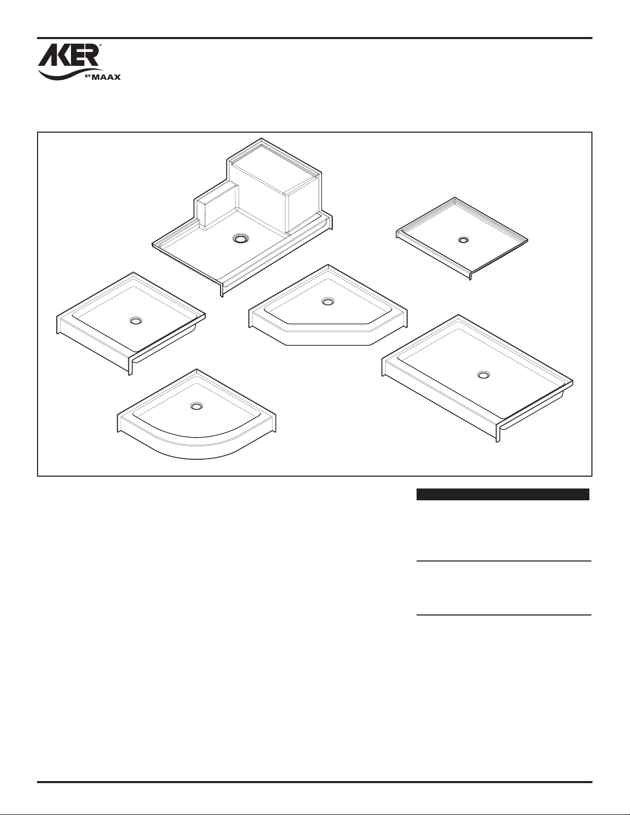
GUIDELINES FOR UNIT
INSTALLATION
XXXXX 141067 141069 141071 141073 141075
NF-6036 SP-3232 SP-3442 SP-3448 SP-3260 SP-NAS
141068 141070 141072 141074 141076 141365
SP-3636 SP-3248 SP-3648 SP-3660 SPCN-3636 SPL-3950
Shower Pans & seated base
XXXXXX
NF-6036
141365
SPL-3950
141067
SP-3232
141068
SP-3636
141076
SPCN-3636
These guidelines are recommended by
Maax Bath Inc. (hereafter “MAAX”) for
the proper installation of their product.
A careful review of these procedures
(and any referenced publications)
before starting is important in avoiding
unnecessary problems resulting in an
improper assembly or installation.
NOTE: All drawings in this publication are
typical, and may appear different than the
actual items being installed. In addition,
optional items may be shown on the units
which may not have been ordered on the
unit being installed.
141075
SP-NAS
141069
SP-3442
141070
SP-3248
141071
SP-3448
Special Notes to Installer
Ü It is the sole responsibility of the installer
to determine, prior to the installation, the
requirements necessary for compliance
with all codes involving the unit or the
installation!
ÜAll paperwork packaged with the unit and
any associated options or accessories
should be saved and presented to the
homeowner upon completion of the
installation!
ÜAll published unit dimensions are for
reference only. Any critical dimensions
required for installation should be taken
directly from the unit being installed!
ÜAny independent changes made to the
unit (or to any options and accessories
supplied with the unit) beyond those
required for normal installation can void
all warranties! (Refer to warranties for
further information.)
141072
SP-3648
141073
SP-3260
141074
SP-3660
Inspection Guidelines
A careful check of the unit should be
conducted upon receipt. Notify your
supplier immediately if any questions or
problems are encountered during this
process.
DO NOT INSTALL ANY UNIT
WITHOUT FIRST ADDRESSING
QUESTIONS WHICH ARISE DURING
THE INSPECTION!
Basic Module Check
ü Check that the unit drain matches the
bathroom drain location.
ü Check for unit surface damage.
ü Check unit color for coordination to
other bathroom fixtures.
Options/Accessories Check
An individual check list is included with
the assembly and installation guidelines of
factory authorized options. Refer to listed
publications for further information before
continuing.
10023063
Page 2

GUIDELINES
FOR UNIT
INSTALLATION
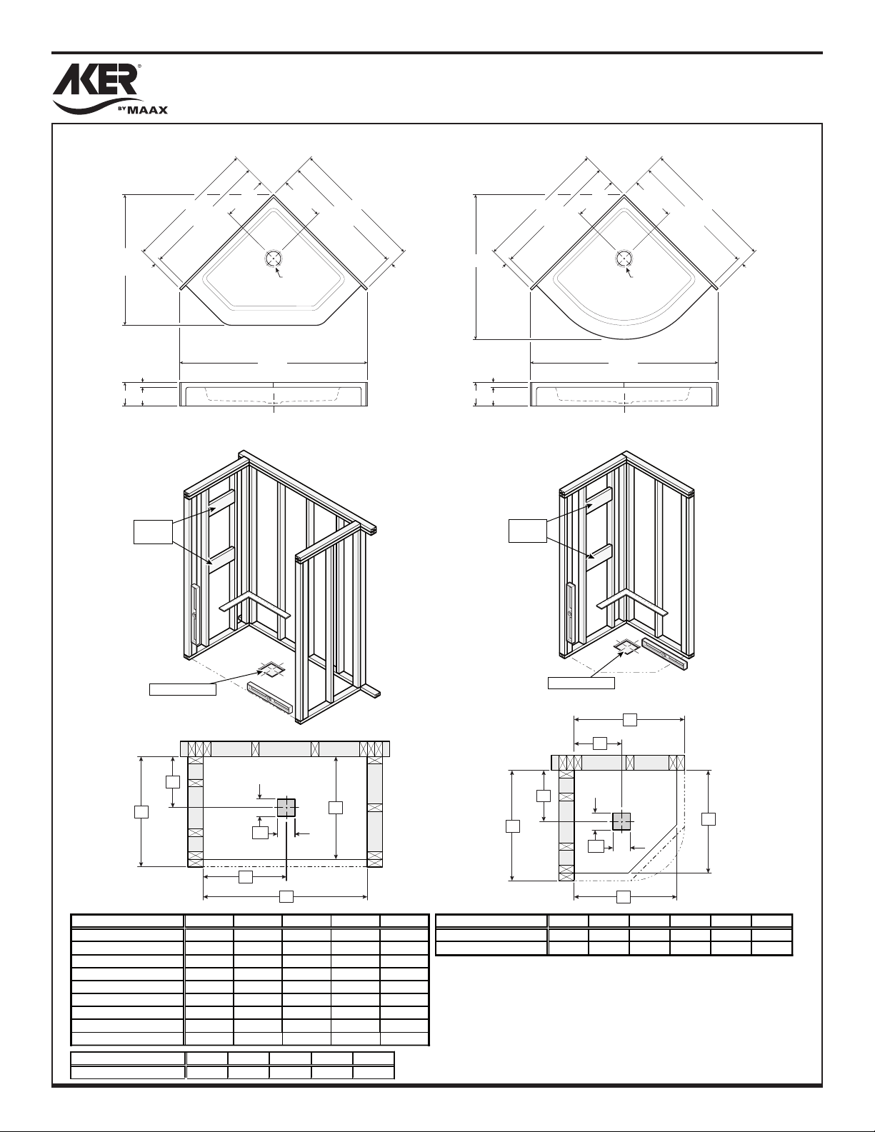
Figure 1a - Unit Data and Dimensional Guidelines (Tolerance: +0/ -3 /8 inch)
Page 2
33-1/2"
7-1/2"
32"
1-1/2"
1-1/2"
6"
33-1/2"
7-1/2"
15-1/4"
32"
1-1/2"
1-1/2"
6"
15-1/4"
16"
141067
SP-3232
24"
Ø 3-3/8" Drain
32"
Ø 3-3/8" Drain
48"
17-1/4"
36"
37-1/2"
7-1/2"
35-1/2"
7-1/2"
1-1/2"
1-1/2"
34"
1-1/2"
1-1/2"
6"
6"
16-1/4"
141068
SP-3636
16"
24"
18"
24"
Ø 3-3/8" Drain
18"
36"
Ø 3-3/8" Drain
24"
48"
35-1/2"
7-1/2"
37-1/2"
1-1/2"
1-1/2"
7-1/2"
34"
6"
16-1/4"
36"
1-1/2"
1-1/2"
6"
17-1/4"
21"
141069
SP-3442
Ø 3-3/8" Drain
21"
42"
Ø 3-3/8" Drain
24"
48"
24"
33 1/2"
7 1/2"
13 1/2"
32"
1-1/2"
1-1/2"
15-1/4"
6"
36"
8 1/4"
141073
SP-3260
18"
6 1/4"
141070
SP-3248
30"
Foot Ledge
3"
Foot Ledge
Flange
60"
60"
Flange
16"
60"
Ø 3-3/8" Drain
30"
Seat
30"
Seat
37 1/4"
1 1/4"
22"
37-1/2"
7-1/2"
22 3/4"
36"
1-1/2"
1-1/2"
17-1/4"
6"
24"
141071
SP-3448
141074
SP-3660
XXXXX
NF-6036
141072
SP-3648
19-1/4"
Ø 3-3/8" Drain
30"
60"
30"
40-1/4"
4"
39-1/4"
1"
1"
3"
141365
SPL-3950
25-1/4"
Ø 3-3/8" Drain
25-1/4"
50-1/2"
10023063
Page 3
GUIDELINES
MODEL ABCDE
141067 /
SP-3232
32" 33-1/2" 32" 15-1/4" 16"
141068 /
SP-3636
36" 37-1/2" 36" 17-1/4" 18"
141069 /
SP-3442
42" 35-1/2" 34" 16-1/4" 21"
141070 /
SP-3248
48" 33-1/2" 32" 15-1/4" 24"
141071 /
SP-3448
48" 35-1/2" 34" 16-1/4" 24"
141072 /
SP-3648
48" 37-1/2" 36" 17-1/4" 24"
141073 /
SP-3260
60" 33-1/2" 32" 15-1/4" 30"
141074 /
SP-3660
60" 37-1/2" 36" 17-1/4" 30"
MODELABCDEF
141075 /
SP-NAS
38" 38" 36-1/2" 36-1/2" 14-1/2" 14-1/2"
141076 /
SPCN-3636
38" 38" 36-1/2" 36-1/2" 14-1/2" 14-1/2"
141365 /
SPL-3950
50-1/2" 40-1/4"39-1/4" 19-1/4" 25-1/4"
MODELABCDE
XXXXX /
NS-6036
60" 37 1/4" 36" 18" 30-1/8"
FOR UNIT
INSTALLATION
Figure 1b - Unit Data and Dimensional Guidelines (Tolerance: +0/ -3 /8 inch)
Page 3
7-1/2"
39-3/4"
1-1/2"
1-1/2"
6"
Fixture
Blocks
38"
36-1/2"
141075
SP-NAS
14-1/2"
51-3/4"
14-1/2"
Ø 3-3/8" Drain
36-1/2"
38"
1-1/2"
7-1/2"
42"
1-1/2"
1-1/2"
6"
Fixture
Blocks
38"
36-1/2"
141076
SPCN-3636
14-1/2"
51-3/4"
14-1/2"
Ø 3-3/8" Drain
36-1/2"
38"
1-1/2"
B
Unit Rough-In Depth
Minimum Alcove Depth
Drain Cut-Out
D
Drain Center
Drain
Cut-Out
5"
E
Drain Center
A
Alcove Lenght / Unit Lenght
Drain Cut-Out
Minimum Alcove Depth
Unit Rough-In Depth
Drain Center
A
E
F
C
Finished Unit Depth
Drain Center
B
Unit Rough-In Depth
Minimum Alcove Depth
5"
Finished Unit Depth
C
Drain
Cut-Out
D
Finished Unit Depth
Framing Requirements
10023063
Page 4
GUIDELINES
FOR UNIT
INSTALLATION
Page 4
Due to individual site variations, exact
guidelines for every situation cannot be
supplied. The recommended framing and
dimensional requirements shown are
for a typical application and may vary,
depending on site requirements.
The dimensions shown in Figure 1a and
1b are from the surfaces where the unit
will be attached. This surface can be
bare studding, dry wall or other suitable
underlayment material.
IT IS IMPORTANT THAT THE FLOOR
AND ALL FRAMING BE SQUARE
AND LEVEL. Framing should be done
using accepted materials and construction
techniques, in accordance with all
applicable codes.
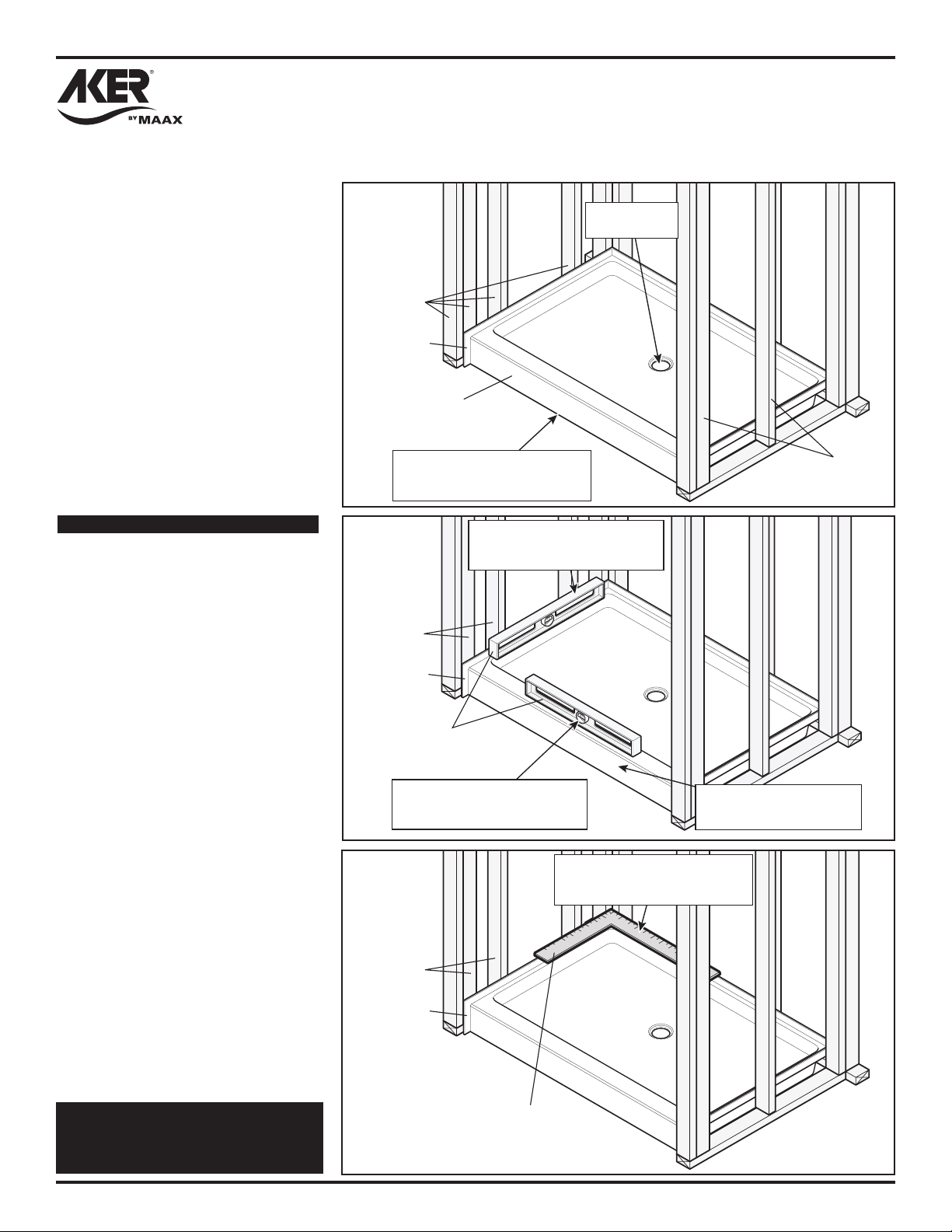
Installation Procedure
With the unit positioned in the alcove,
several details must be checked prior to
securing the unit in place (Figure 2a, 2b
and Figure 2c);
ü Confirm dam is resting flush on the floor.
ü Confirm drain alignment.
ü Confirm the top of unit is level on all sides.
ü Confirm the unit is square in the alcove
framework.
ü Confirm the front inside corner is plumb
at each end. (This is critical for the
proper installation of an enclosure)
The unit must be positioned square in
the alcove framework. The use of shim
or filler material behind the fastening flange
at each framing member may be required
to maintain the unit in the proper position.
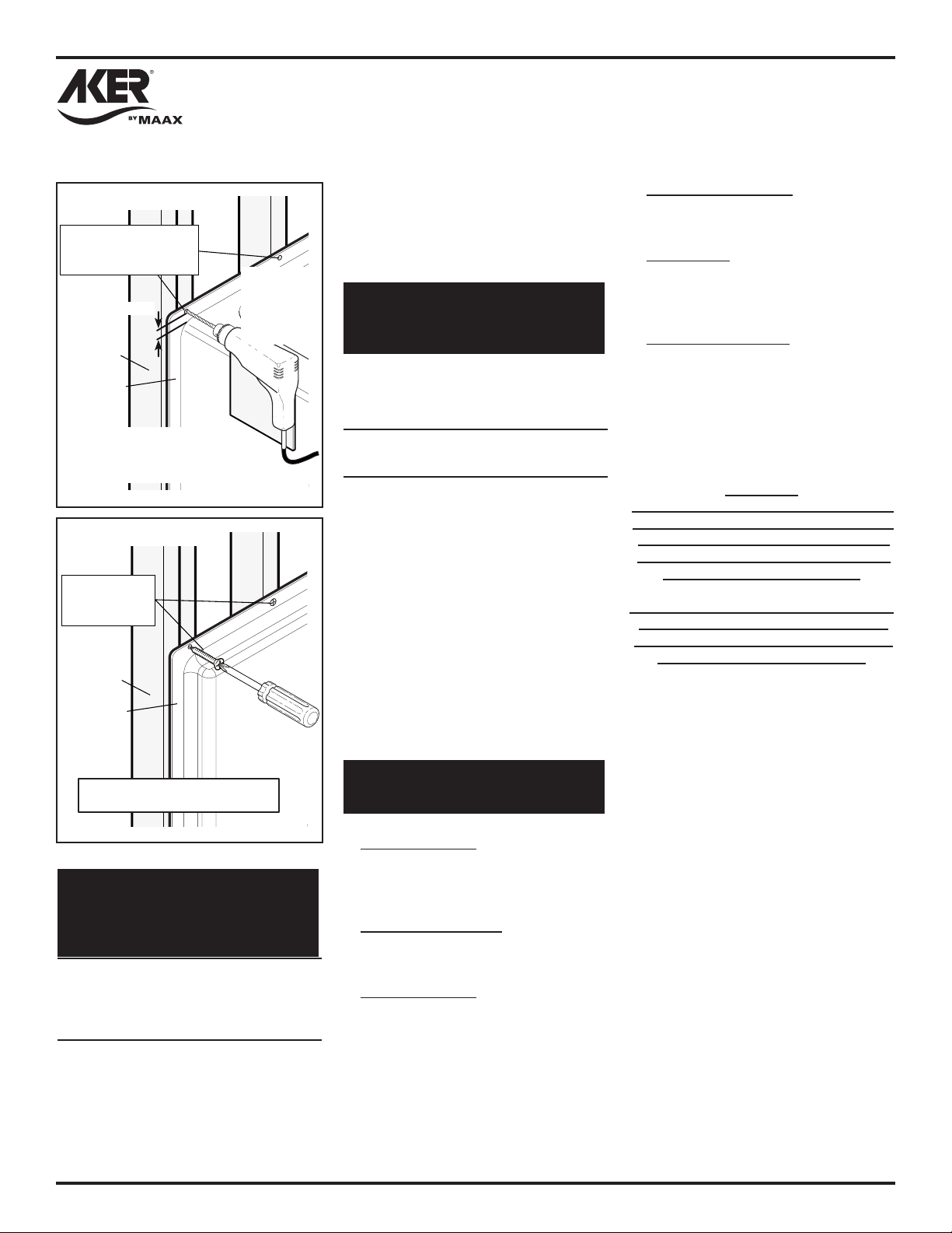
After the unit is confirmed leveled and square
in the alcove, drill a 1/8 inch hole through the
fastening flange at each framing member.
THE BOTTOM OF ALL HOLES IN THE
FLANGE HAVE TO BE AT LEAST 8MM (0.3
INCHES) ABOVE THE BASE THRESHOLD!
Secure the unit in place across the back
wall first, followed by the flanges at each
end and along the front flanges, using
1-1/4 inch long screws or other appropriate
fasteners. Continuously check to confirm
the base remains square within the alcove
as it is being secured. (Figure 3a and 3b)
Figure 2a Unit
Installation
Procedure
Wall
Framing
Fastening
Flange
1. Position the
Shower Pan
in Framed Area
Confirm bottom of front dam is
resting flush on the floor along
the entire length of pan.
Figure 2b Unit
Installation
Procedure
Wall
Framing
Fastening
Flange
2. Level the
Shower Pan
in Framed Area
Confirm the shower pan is level
from side-to-side accross the
front and the back of the unit.
Confirm the shower pan is level
Figure 2c Unit
Installation
Procedure
Wall
Framing
Fastening
Flange
Confirm Drain
Alignment
Wall
Framing
from front-to-back accross
each end of the unit.
NOTE: If unit is equipped with
leveling legs put shims under
them in order to level the base
Confirm the shower pan is
square within the framed area
at all corners.
NOTE: IF UNIT IS EQUIPPED WITH
LEVELING LEGS PUT SHIMS UNDER
THEM IN ORDER TO LEVEL THE
3. Square the
Shower Pan
in Framed Area
BASE
10023063
Page 5
GUIDELINES
Fi
Fi
FOR UNIT
INSTALLATION
Page 5
gure 3a - Securing Unit
Drill 1/8 inch hole
through flange at each
framing member
0.3" (8 mm)
Wall
Framing
Fastening
Flange
Note: the bottom of all holes in the flange have
to be at least mm or 0.3” above the base threshold.
Note : Chaque trou dans la bride doit être à une distance
minimale de 8mm(0.3po.) de la surface de la base.
Nota : la parte inferior de todos los agujeros de la brida tiene
que ser al menos de 8 mm o 0,3” sobre el umbral de base.
gure 3b - Securing Unit
Secure unit
to framing with
1-1/4" screws
Wall
Framing
Fastening
Flange
Fill all holes with
Remplir les trous
avec du silicone
Llenar los agujeros
con silicona
silicone
Refer to, and follow, the assembly and
installation instructions provided with the supply
valves and drain system. Carefully check all
fittings and connections for leaks.
Unit Surface Care
WARNING!
NEVER USE ABRASIVE MATERIALS
NOR ABRASIVE CLEANERS ON THE
UNIT SURFACE!
EXTREME CAUTION is urged regarding
the use of any cleaner, acid or solvent
on the unit surface.
READ, AND FOLLOW ALL PACKAGE
LABELS AND INSTRUCTIONS!
Through routine use, the unit surface can
collect residues from soap, bath additives
and natural body oils. Additional deposits
can also collect from minerals or particles
found in the water.
After each use, wipe the excess water
from the unit. This practice will reduce the
build-up of deposits and help maintain the
natural unit lustre.
Following a thorough surface cleaning,
an application of quality automotive wax
will help reduce major accumulations. The
actual schedule for cleaning, and waxing, will
depend on unit usage and water quality.
• Hard Water Scales: Liquid scale
remover or white vinegar, applied full
strength. (Rinse surface thoroughly.)
• Mold/Mildew: Liquid mildew remover
or baking soda and water paste. Apply
paste and allow to fizz several minutes.
(Rinse surface thoroughly.)
• Construction Adhesive: Soften adhesive
with hand held dryer and peel off
adhesive. (Caution is advised when
using any electrical device near water.)
For stubborn cases, apply rubbing alcohol
or nail polish remover, full strength, to
adhesive. (Rinse surface thoroughly.)
WARNING!
BATH MATS OR OTHER ITEMS WHICH
ARE HELD IN PLACE USING SUCTION
AGAINST THE UNIT SURFACE MUST
BE REMOVED FROM THE FLOOR OF
THE UNIT AFTER EACH USE.
OVER A PROLONGED PERIOD, FAILURE
TO REMOVE THESE TYPES OF ITEMS
FROM THE BOTTOM OF THE UNIT CAN
RESULT IN SURFACE DAMAGE.
WARNING!
CAUTION: Protect unit surface
with a shield when fastening
AVOID APPLYING WAX TO THE UNIT
BOTTOM!
• Routine Cleaning: Mild, non-abrasive
cleaner specifically formulated for gelcoat
WARNING! THE UNIT BOTTOM
SHOULD BE CLEAR OF ALL
POTENTIALLY DAMAGING DEBRIS
AND THE SURFACE PROTECTED
BEFORE STEPPING INSIDE.
CAUTION: It is advisable to protect
the unit surface with a thin plywood or
cardboard shield while fastening the
flange to the framing.
and acrylic surfaces recommended.
(Rinse surface thoroughly.)
• Heavy Soap Deposits: Liquid ammonia
household cleaner, applied full strength.
(Rinse surface thoroughly.)
• Stubborn Stains: Liquid household
cleaner or hydrogen peroxide, applied
full strength. Place a saturated clean rag
directly on stain and let stand several
hours. (Rinse surface thoroughly.)
For extreme cases, buff area with white
automotive polishing compound until stain
disappears, and apply a quality automotive
wax to surface.
Water Supply and Drain Connections
10023063
Page 6

Page 7

Page 8
GUIDELINES
FOR UNIT
INSTALLATION
Page 8
LIMITED WARRANTY
AKER Plastics Company Inc. (hereafter “MAAX”) offers the following express limited warranty on each of its products. This warranty extends only to
the original owner/end-user for personal household use. For commercial uses, additional limitations apply.
MAAX warrants acrylic units to be free from defects in workmanship and materials under normal use and service for a period of twenty five (25) years
from the initial date of purchase by the owner/end-user, contractor or builder from an authorized dealer.
MAAX warrants fiberglass units to be free from defects in workmanship and materials under normal use and service for a period of five (5) years from
the initial date of purchase by the owner/end-user, contractor or builder from an authorized dealer.
Any product reported to the authorized dealer or to MAAX as being defective within the warranty period will be repaired or replaced (with a product of
equal value) at the option of MAAX. This warranty extends to the original owner/end-user and is not transferable to a subsequent owner.
Neither the distributor, authorized MAAX dealer nor or any other person has been authorized to make any affirmation, representation or warranty other
than those contained in this warranty; any affirmation, representation or warranty other than those contained in this warranty shall not be enforceable
against MAAX or any other person.
MAAX reserves the right to modify this warranty at any time, it being understood that such modification will not alter the warranty conditions applicable
at the time of the sale of the products in question.
Limitations
This warranty shall not apply following incorrect operating procedures, breakage or damages caused by fault, carelessness, abuse, misuse,
misapplication, improper maintenance, alteration or modification of the unit, as well as chemical or natural corrosion, accident, fire, flood, act of God
or any other casualty. This warranty shall not apply to stains caused by ferrous water or hard water.
The owner/end-user of the product covered by the present warranty is entirely responsible for its proper installation and electrical wiring. MAAX neither
installs nor supervises the installation, nor hires a contractor for this purpose, and consequently cannot be held responsible for any default, breakage
or damages caused thereby or resulting thereof, either directly or indirectly. The owner/end-user must provide access to the components of the product
as described in the installation guide, so that MAAX can execute the warranty specified herein. If such access is not available, all expenses to provide
said access will be the responsibility of the owner/end-user.
This warranty does not apply to products or equipment not installed or operated in accordance with instructions supplied by MAAX and all applicable
rules, regulations and legislation pertaining to such installations.
MAAX strongly recommends that its products - for example, but without limitation, shower doors and other items - be installed by professionals with experience
in bathroom products. Installation of shower doors by an inexperienced person may result in glass breakage and, consequently, cause personal injury or death.
MAAX is not liable for any costs, damages or claims resulting from the purchase of products that do not fit through openings or existing structures. MAAX is not
liable for any costs, damages or claims resulting from defects that could have been discovered, repaired or avoided by inspection and testing prior to installation.
MAAX is not liable for personal injuries or death to any person or for any direct, special, incidental or consequential damage, loss of time, loss of profits,
inconvenience, incidental expenses, labor or material charges, or any other costs resulting from the use of the product or equipment or pertaining
to the application of the present warranty, or resulting from the removal or replacement of any product or element or part covered by this warranty.
EXCEPT AS OTHERWISE PROVIDED ABOVE, MAAX MAKES NO WARRANTIES, EXPRESS OR IMPLIED, INCLUDING WARRANTIES OF
MERCHANTABILITY AND FITNESS FOR A PARTICULAR PURPOSE OR COMPLIANCE WITH ANY CODE.
In any case, MAAX cannot be liable for any amount over and above the purchase price paid for the product by the owner/end-user, contractor or builder.
Commercial Limitations
In addition to the above conditions and limitations, the warranty period for products installed for commercial applications or used in commercial ventures
is of one (1) year from the initial date of purchase by the owner/end-user, contractor or builder from an authorized dealer. MAAX is not responsible for
loss of use or profit under any circumstances. If the product is used as a display, the warranty period begins when the product is placed on display.
This warranty gives the owner/end-user specific legal rights. The owner/end-user may also have other rights which vary from one state and/or province to
another.
Warranty service
In order to obtain service provided under this warranty during regular business hours, contact the dealer or distributor who sold the unit, or MAAX directly.
MAAX will provide the warranty service described above when the following conditions have been met: (1) the failure is of the nature or type covered
by the warranty; (2) the user has informed an authorized MAAX Agent or Warranty Service Department representative of the nature of the problem
during the warranty period; (3) conclusive evidence (e.g., proof of purchase or installation) is provided to the foregoing by the user proving that the
failure occurred or was discovered within the warranty period and (4) an authorized independent service person or company representative has been
permitted to inspect the product during regular business hours within a reasonable time after the problem was reported by the user.
MAAX’s warranty obligation shall be discharged upon tender of replacement or repair. The customer’s refusal to accept the tender terminates MAAX’s
warranty obligation.
MAAX products are certified by one or more of the following certification agencies: CSA, UL, IAPMO, ULI, INTERTEK (ETL), WARNOCK HERSEY,
US TESTING, NAHB.
Certain models are pending approval.
Certification may be ended by MAAX or certification agencies without notice.
AKER is a registered trademark of AKER PLASTICS COMPANY Inc.
MAAX is a registered trademark of MAAX Canada Inc.
After Sales Service
718 Mid-Atlantic Parkway
Martinsburg, WV 25401
Phone: 800-962-2537 • 304-263-2525
Fax: 304-263-2379
www.akerbymaax.com
© 2008 MAAX Bath Inc. 2018-08-08 10023063
0510 10023063
 Loading...