

Page 1
GUIDELINES
FOR UNIT
INSTALLATION
View Installation Video - Scan QR code with a mobile device
Voir V idéo d'installation - Balayer QR code avec un dispositif mobile
Ver video de instalación - Escanear código QR con un dispositivo mobil
Outlook Plus Series
FHA 4836 SH - FHA COMPLIANT SERIES 141304
FHA 6032 TS - FHA COMPLIANT SERIES 141305
OPS-3636 141271-141272-141273-141274-141275-141276-141277-141278-141366-141378
OPS-3636-RS 141321-141322-141323-141324-141325-141326-141327-141328-141367-141379
OPS-6030 141287-141288-141289-141290-141291-141292
OPS-6030-RS 141329-141330-141331-141332-141333-141334
OPS-6036 141294-141295-141296-141297-141298-141299-141300 -141368-141380
OPS-6036-RS 141336-141337-141338-141339-141340-141341-141342-141369-141381
OPTS-6032 141309-141310-141311-141312-141313-141314-141315-141316-141370-141382
Read carefully before proceeding. TO BE KEPT BY THE END USER.
Keep the serial number for the unit
PLEASE READ INSTRUCTIONS CAREFULLY BEFORE PROCEEDING
Before starting
Upon reception, check if your shower is in good condition and make sure that all parts are included. If you have a problem, please
contact immediately your distributor.
Required equipment
• Level • Measuring tape • Pencil
• Electric drill • #8 x 1" wood screws • Square
• Silicone • Safety goggles
• Wood shims • Phillips screwdriver
• Cement or similar composite material
WARNING:
For optimum operation, it is important that the unit be installed perfectly on a leveled floor. Handle metal parts with
care. During installation, protect shower floor with the cardboard packaging. This will prevent damaging the finish.
DO NOT BUILD THE SURROUNDING STRUCTURE BEFORE RECEIVING YOUR UNIT. Structure measurements should be
verified against the unit to ensure a proper fit.
The grab bars and seats must be installed before unit installation.
Consult local building codes to make sure the installation complies with standards.
MAAX is not responsible for problems caused by installations that were not conducted in compliance with the directives
in this guide.
A two person installation
is recommended.
ATTENTION
In accordance with standards, the finished entrance height of shower stalls must not exceed ½ inch (13 mm).
Because of the possible water leaks between the lip of the shower and the curtain, MAAX RECOMMENDS THE
INSTALLATION OF A FLOOR DRAIN OUTSIDE THE UNIT, in rooms where the aforementioned units will be installed.
10032587
Page 2
INSTALLATION
C
e
STEP
FREE SPACE
1
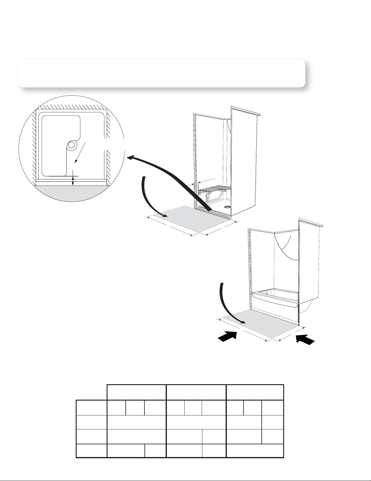
The bathroom configuration must include a clearance zone to allow the user to have access to the unit.
In order to respect these various standards, refer to the table below. It is very important that the free space respect
the dimensions. See Fig.A and table.
Distance between the seat and the clearance zone
G
Clearance zone
learance zon
Clearance zone
C
A
Clearance zone
Entry #1
B
A
B
Entry #2
Fig. A
Shower 36''x36''
Shower 48''x36''
Standard
A (min in.)
B (min in.)
C (max in.)
1 Mass = Massachusetts
ANSI
from the control wall
3
ADA
48
Mass
N/A
Shower (60''x36'')
Shower (60''x30'')
1
ANSI
2
3
ADA
Mass
60
3636 30
N/A
(Tub shower 60''x32'')
1
ANSI
60
ADA
N/A
Mass
48
3630
1
Page 3
STEP
INSTALLATION
2
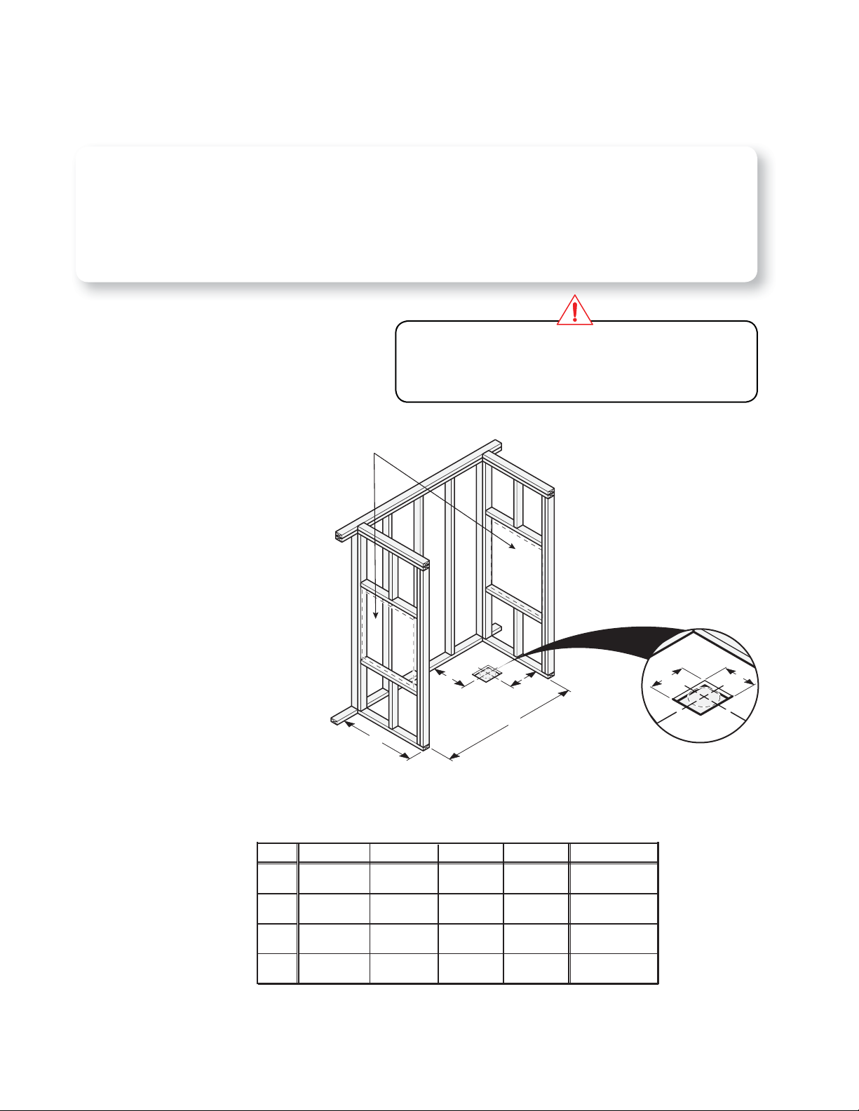
A sturdy frame is required to ensure stability of the unit, once installed.
For units equipped with a stainless steel soap dish, make sure that there is no stud behind the soap dish hole.
Construct the alcove in accordance with Fig. A and table dimensions.
NOTE: STRUCTURE MEASUREMENTS MUST BE VERIFIED AGAINST THE UNIT TO ENSURE A PROPER FIT.
All dimensions are expressed in inches and millimeters.
FRAMING
Note: The following measurements are not those of the
unit but those required for the installation (± ¼") ; for easier
installation add 1/4" (6 mm) to dimensions A and B only.
Note: Some units are available with left-hand or right-hand
drain; check the drain position before drilling the floor.
Allow an accessway to the faucet
C
D
A
B
Fig. A
(36"x36'') (60"x36") (60"x30") (Tu b s h o w e r 6 0 " x 3 2 " )
A
B
C
D
38 3/4
984
39
991
19 1/2
495
19 3/8
492
(48"x36'')
47 7/8
1216
37 1/8
943
17 1/4
438
23 7/8
606
62 1/2 62 7/8 59 3/4
1588 1597 1518
39 1/4 33 1/4 34
845 845 864
19 5/8 15 1/2 15 1/8
498 394 394
31 3/8 31 3/8 10
797 797 254
3
6"
6"
Page 4
STEP
INSTALLATION
3
CONTROL AREA
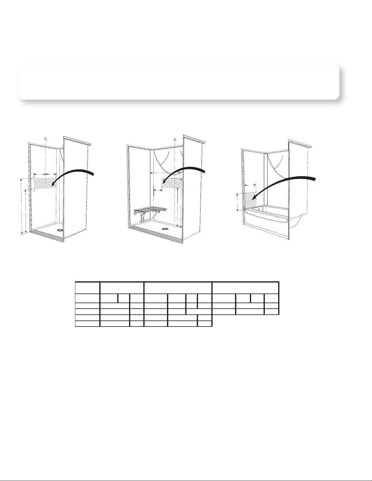
The control area must be inside a target zone and must not exceed this zone in order to respect the various standards. Fig. A.
The control area can differ slightly from one standard to another.
Refer to the table below.
NOTE: If unit is with a complete compliant package, the control hole will be factory drilled.
C
L
B
A
C
D
Shower control area
C
L
E
F
H
G
Shower control area
I
J
Shower control area
#
Standard ANSI ADA Mass
A (max in.)
B (max in.)
C (max in.) G (min in.)
D (min in.) H (max in.)
Shower (36"x36")
Shower (48"x36")
15
0
48
38 42
18
18
72
Standard ANSI ADA Mass
E (max in.)
F (min in.)
1 Mass = Massachusetts
* If a seat is included
Fig. A
Shower (60"x36")
Shower (60"x30")
27
27
16
1 1/2 above the grab
bar
48
Tub shower (60"x32")
Standard ANSI ADA Mass
I (max in.)
27
*
J (max in.)
0
42
72
15 5/8
18 1/2
N/A
N/A
4
Page 5
STEP
INSTALLATION
4
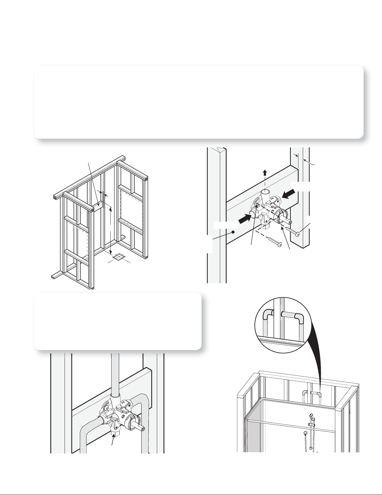
A trap door measuring at least 30" x 28" (762mm x 711mm) behind EACH shower model is highly recommended to give
access to the valve and plumbing for maintenance and repairs.
a) The valve must be installed at the following heights, Dim. A for showers from 45" to 48" (1143mm - 1219mm) and 32"(813mm)
for tub showers. Fasten a 3 in. (76.2 mm) high wood block. The depth (2") is based on the exterior surface of the studs in order
to install the wood block (Fig. A-B).
b) Fasten hot and cold water couplings.
c) Fasten valve using two screws. (Fig. B) Make sure center of valve is at the same height as the center of the hole in the shower
wall in relation to the floor.
d) Connect water supply lines so hot water (left) and cold water (right) are properly connected in relation to the valve body. (Fig. B)
e) The water pipe connecting the valve to the hand-held shower connector must rise above the shower wall. (Fig. D)
Install a horizontal stud
to fasten the valve
VALVE INSTALLATION
"Shower"
2”
Cold water
2”
Wood screw
A
Wood block
3" (76.3mm)
High
Hot water
Hole to fasten
fitting flange
Hole to fasten
fitting flange
#8 x 1"
Fig. A
NOTE: Before proceeding with the final assembly, make
sure plumbing is watertight. Fig. C
WARNING: if drain is not connected, insert a flexible pipe on
the shower head to evacuate water to a proper location. You
can also use a pail. Check the whole assembly for any leaks
and proceed with corrective action if necessary (ex.: tightening
joints).
Plug
Fig. C
Fig. B
Fig. D
5
Page 6
STEP
INSTALLATION
5
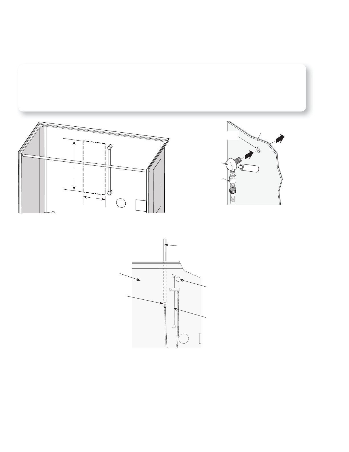
Drill a 1" diameter hole in the recommended target zone marked with the dotted line rectangle as shown in Fig. A.
Apply a bead of silicone on the inside surface of the hand-held shower connector and insert it in the previously drilled hole
as shown in Fig. B.
The hand-held shower connector must be fastened behind the unit's wall with the piping rising above the unit. Fig. C.
The hand-held shower will rest on sliding support bar. Fig. C.
HAND-HELD SHOWER INSTALLATION
Height of the
sliding bar
8"
Fig. A
Ø 1”
Hand held shower
connector
Vacuum breaker
Fig. B
Drilled hole
Unit wall
To valve
Silicone
Unit wall
Hand-held shower
connector
Piping above
the unit
Fig. C
Hand-held shower
Support bar
6
Page 7
STEP
INSTALLATION
6
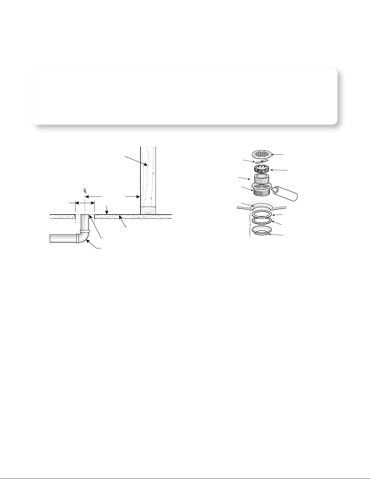
Cut drain pipe flush to the floor. Fig. A.
Apply a bead of silicone under flange of drain head. Insert drain head into the drain hole of the unit. Tighten locknut with
friction ring and gasket to secure shower drain to shower floor. Fig. B.
Before fi nal installation of the drain, the unit (shower or tub-shower) has to be completely installed. T o fi nish drain installation
go to step 12.
(152 mm)
DRAIN ON SHOWER INSTALLATION
Stud wall (Framing)
see step 2
for correct
6"
measure
Sub floor
Cut flush to the floor
Locking
wrench
Rubber calking
gasket
Drain head
Base
Under the base
Strainer
Calking
nut
Silicone
Gasket
Friction ring
Locknut
Fig. A
Drain pipe
Fig. B
7
Page 8
STEP
INSTALLATION
7
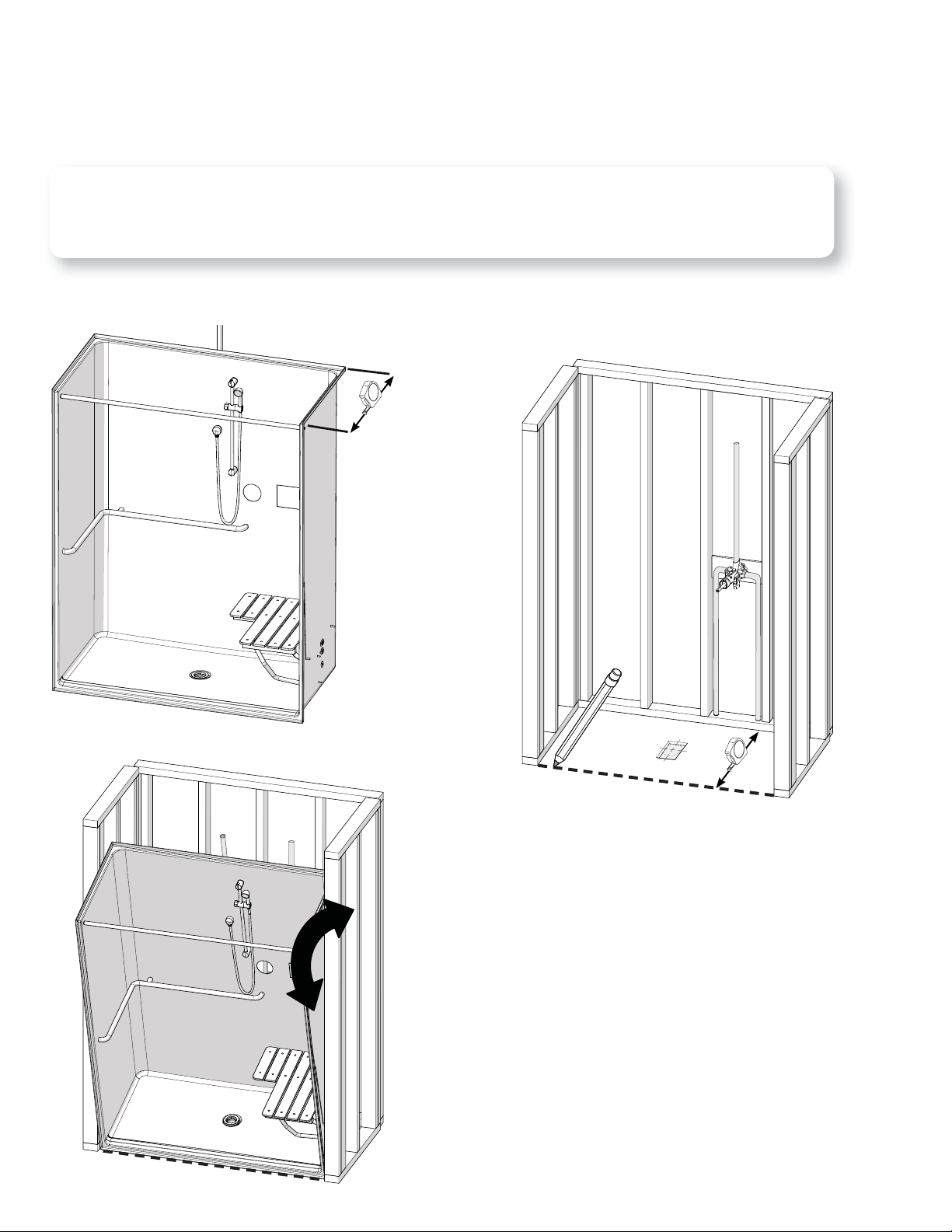
A) Before placing the unit in the alcove, measure the depth. Fig.A.
B) Using the depth project and trace a line as shown in fig.B.
C) Place the unit in the alcove, use the traced line as a reference to help in positionning the unit. Verify that everything fits
(drain pipe, valve and soap dish). Remove the unit from the alcove. Fig.C.
UNIT INSTALLATION
Fig. A
Fig. C
Fig. B
8
Page 9
STEP
INSTALLATION
8
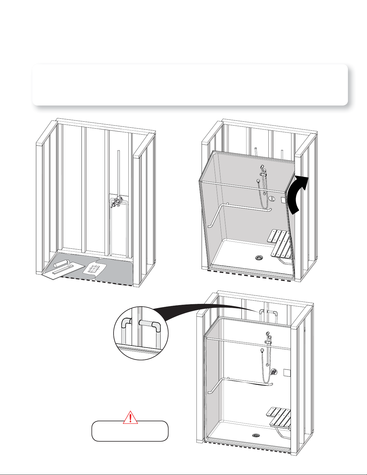
A) Apply a thin layer of mortar. Leave a gap of at least 5 inches around the drain hole as shown. Fig.A.
B) Tip to the front the unit and place it on the previously marked line as shown. Fig.B. Make sure that everything (drain, pipe and
valve) is on the right place. Lower the unit slowly into place. Fig.B.
C) Connect plumbing under the top horizontal stud as shown. Connect plumbing and drainage according to standards. Make
sure that joints are waterproof. Fig.C.
UNIT INSTALLATION
Fig. B
Fig. A
Fig. C
Put cardboard on shower fl oor
to protect the surface during
installation.
9
Page 10
STEP
INSTALLATION
9
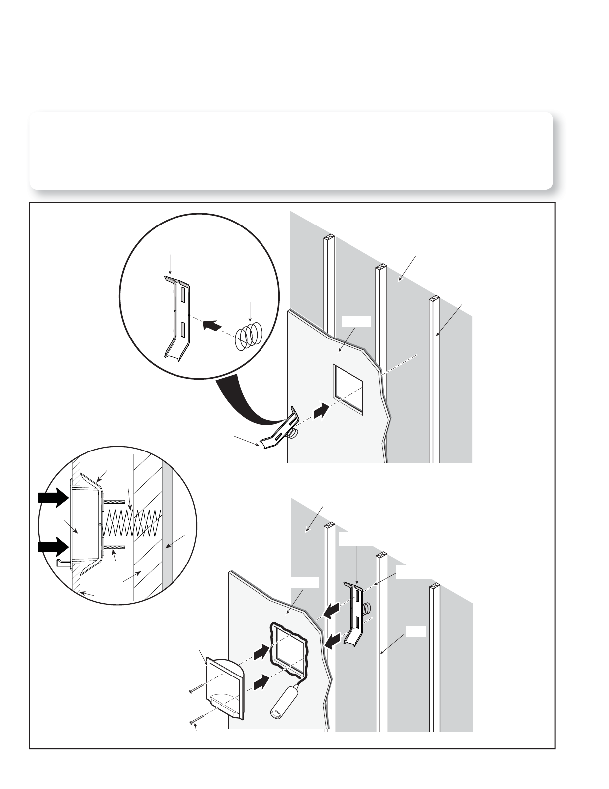
OPTIONAL SOAP DISH INSTALLATION
The soap dish must be installed after having positioned the unit in the frame. If the option is chosen an opening for inserting
the soap dish will be factory drilled.
Install the spring at the center of the soap dish support. Fig. A. Then insert the support in the opening so that the support with
the spring is compressed between the backing of the unit and the back wall. Fig. B.
Apply a bead of silicone around the pre-drilled opening. Screw the soap dish in the support until it is tight against the shower
wall. Fig. C.
Soap dish
support
Spring
Unit wall
Back wall
Stud
Fig. A
Soap
dish
Fig. B
Side cut view
Soap dish
support
Spring
Screw
Stud
Unit wall
Back
Wall
Soap dish
Soap dish
support
Unit wall
Silicone
Back wall
Soap dish
support
The soap dish support is hold compressed
between the unit and the back wall
Stud
Fig. C
Fastening screw
10
Page 11
STEP
INSTALLATION
10
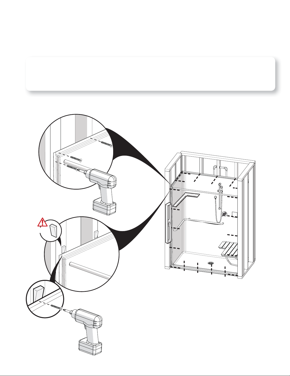
Level and square the unit.
Fasten unit using #8 screws. Start by fastening a screw in each bottom corner of the unit. Drive in the other screws after checking
that the unit is correctly positioned, leveled and squared. Fasten screws into the fastening flange, 8" (20cm) apart along the
vertical sides and the floor. For the horizontal sides, fasten a screw in front of each stud.
Use shims as needed to level the unit.
FASTENING OF THE UNIT TO THE FRAME
Shims
11
Page 12
STEP
INSTALLATION
11
WARNING: Upon reception, make sure that all parts of the valve are included. If you have a problem, please contact immediately
your distributor.
Always cut off the water supply before removing or disassembling a valve. Turn the valve on to release any water
pressure and to make sure the water supply has indeed been cut off.
IMPORTANT: As mentioned in step 3, it is highly recommended to include an access to the plumbing connections
measuring at least 30" x 28" (762 mm x 711 mm). This access will allow you to easily repair or disassemble the connections.
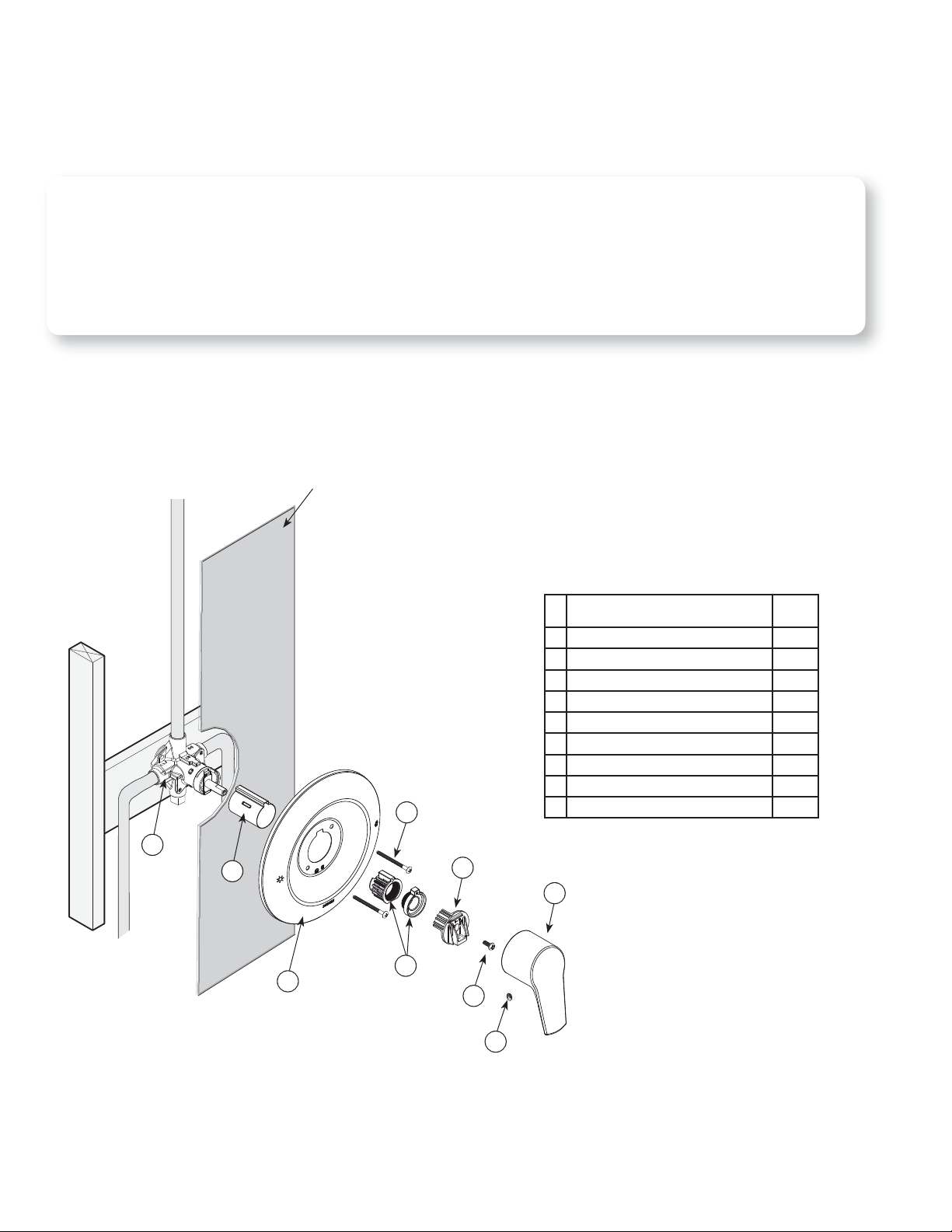
Assemble the valve as shown in Fig.A.
Fig. A
VALVE INSTALLATION
Shower wall
# Description Qty
1 Valve body 1
2 Chrome sleeve 1
3 Chrome face plate 1
4 Temperature limit stop 1
5 Face plate screws 2
6 Handle adapter 1
7 Handle adapter screw 1
8 Handle screw 1
5
1
2
4
3
6
7
8
9 Chrome handle 1
9
12
Page 13
STEP
INSTALLATION
12
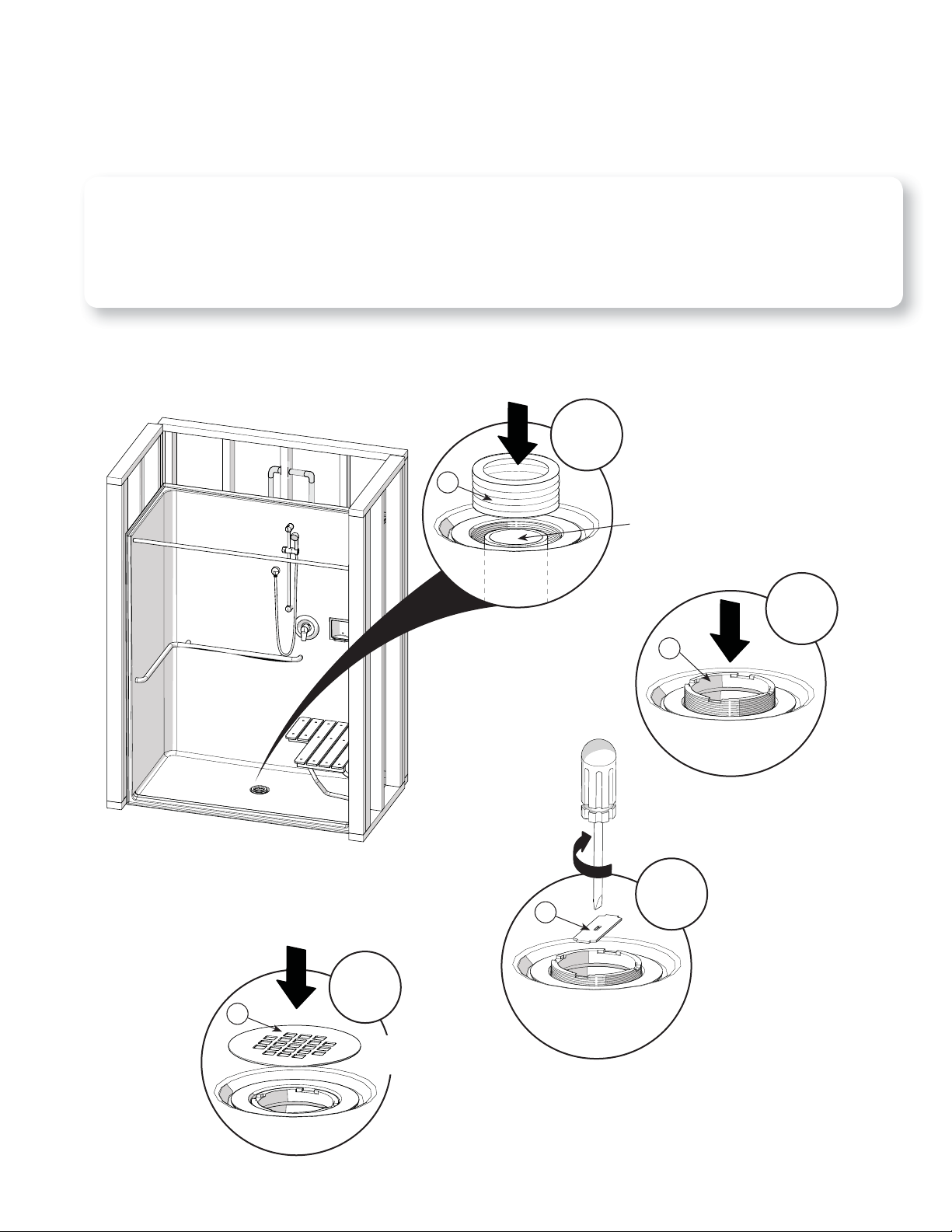
A) Insert rubber calking gasket (1) over drain pipe as shown.
B) Screw calking nut (2) over drain head.
C) Fasten calking nut with locking wrench (3) provided to secure shower drain to pipe. Fully tighten to ensure waterproofing. Then
remove the locking wrench.
D) Push down strainer (4) until it snaps into place on top of shower drain.
DRAIN FINAL INSTALLATION
A
1
Drain pipe
B
2
3
C
D
4
CLICK!
13
Page 14
INSTALLATION
STEP
13
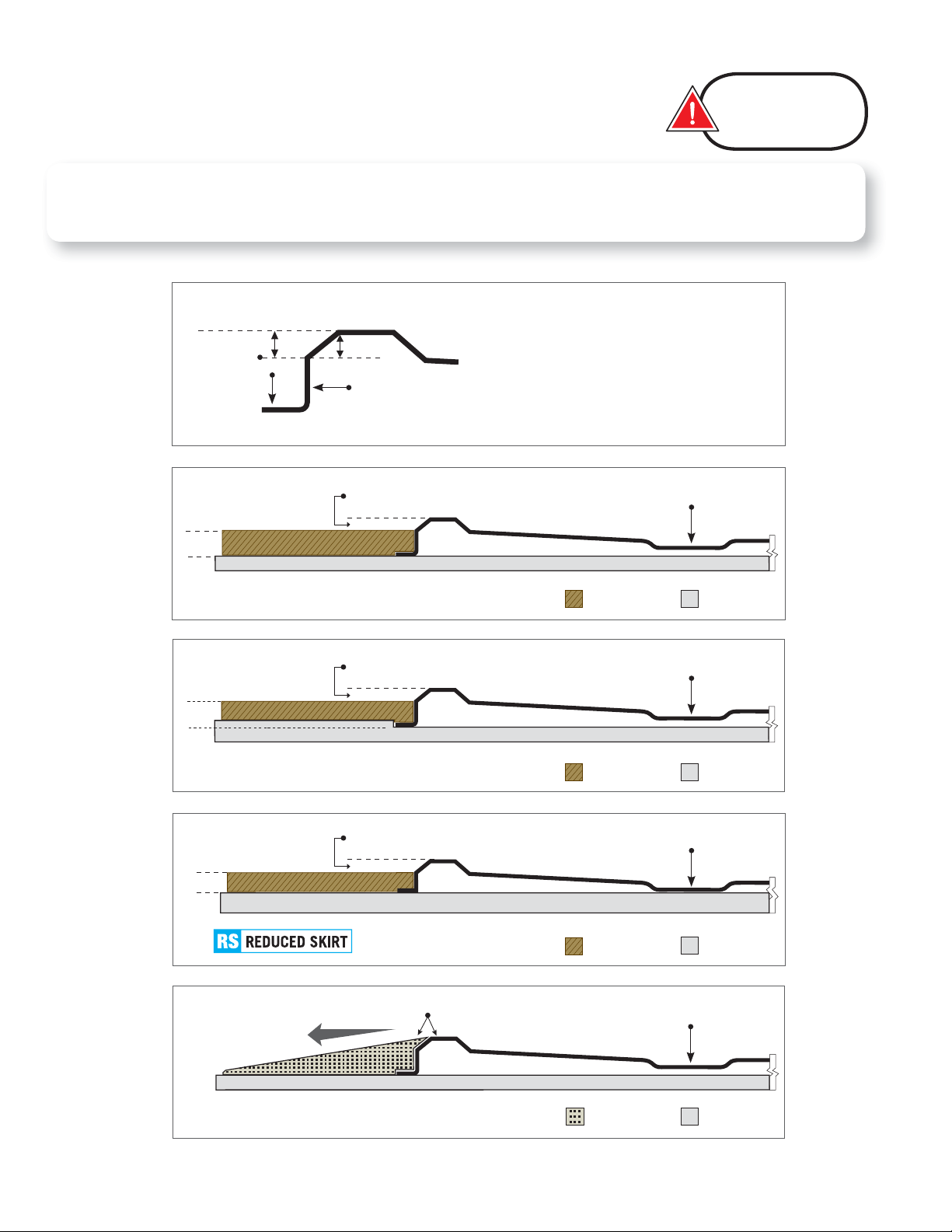
Important: The finished height of the threshold must comply with the following standards:
US: maximum height of 1/2" (13mm) in accordance with ADA/ANSI/ICC A117.1 (Accessible and Usable Buildings and Facilities).
This requirement does not apply to tub-showers.
DAM PROFILE
Finished floor
FINISHED FLOOR INSTALLATION
1
/8’’ Skirt shown)
(1
½"
Flange
Threshold
Skirt
Whichever unit or method you choose,
code compliance comes easily. Simply
ensure the top of finished floor meets
the start of the sloped exterior threshold.
OPS ONLY
ON-FLOOR
INSTALLATION
1 1/8’’
Codes require max. ½" level change
Drain
RECESSED IN-FLOOR
INSTALLATION
1 1/8’’
ON-FLOOR
INSTALLATION
¾’’
ACCESS RAMP
Ramp
Codes require max. ½" level change
Codes require max. ½" level change
Same height
Finished floor
Finished floor
Finished floor
Subfloor
Drain
Subfloor
Drain
Subfloor
Drain
1
1
/8’’ Skirt shown
SubfloorRamp
14
Page 15
INSTALLATION
STEP
FINISH
14
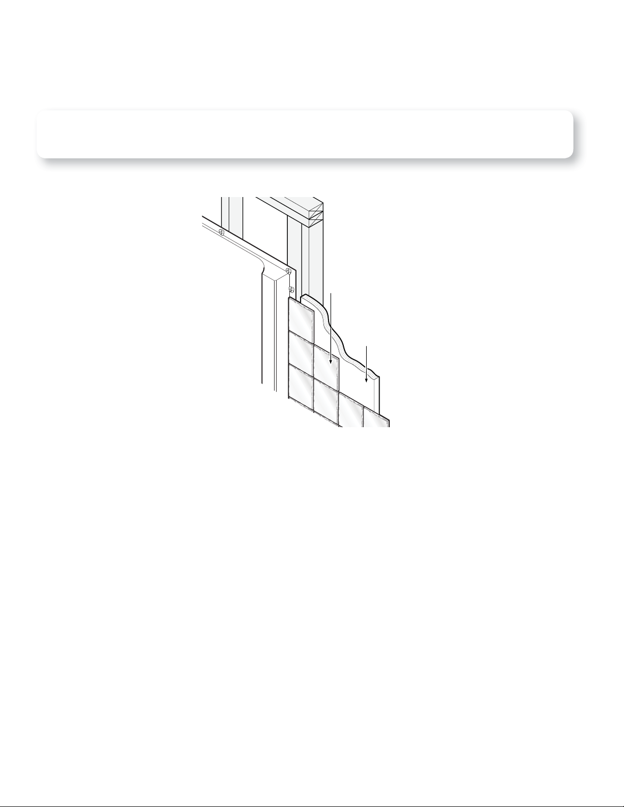
Finishing panels (plasterboard, ceramic tile, etc.) should completely cover the fastening flange (Fig. A). The joint between the
wall panels and the finishing panels can be covered with a joint compound, a plastic stripe, or a tile strip.
To prevent water infiltration, apply a bead of silicone between the floor and the threshold of the unit.
Wall finish
Water proof backer
board or
water proof
Drywall
Fig. A
15
Page 16
LIMITED WARRANTIES
MAAX Bath Inc. (hereafter «MAAX») offers the following express limited warranties on its products. These warranties extend only to the original owner/
end-user for personal household use and start from the manufacturing date of the unit. For commercial uses, additional limitations apply.
MAAX warrants acrylic units to be free from defects in workmanship and materials under normal use and service for a period of twenty five (25) years
from the initial date of purchase by the owner/end-user, contractor or builder from an authorized dealer.
MAAX warrants fiberglass units to be free from defects in workmanship and materials under normal use and service for a period of five (5) years from
the initial date of purchase by the owner/end-user, contractor or builder from an authorized dealer.
Any product reported to the authorized dealer or to MAAX as being defective within the warranty period will be repaired or replaced (with a product
of equal value) at the option of MAAX. Costs for freight associated with shipping of replacement product/parts might be charged to customer. In no
event will MAAX be liable for the cost of repair or replacement of any installation materials, including but not limited to, tiles, marble, etc. This warranty
extends to the original owner/end-user and is not transferable to a subsequent owner.
Neither the distributor, authorized MAAX dealer nor any other person has been authorized to make any affirmation, representation or warranty other
than those contained in this warranty; any affirmation, representation or warranty other than those contained in this warranty shall not be enforceable
against MAAX or any other person. MAAX reserves the right to modify this warranty at any time, it being understood that such modification will not
alter the warranty conditions applicable at the time of the sale of the products in question.
Limitations
This warranty shall not apply following incorrect operating procedures, breakage or damages caused by normal wear and tear, fault, carelessness, abuse,
misuse, misapplication, improper maintenance, alteration or modification of the unit, as well as chemical or natural corrosion, accident, fire, flood, act of God or
any other casualty. This warranty shall not apply to stain or malfunction caused by ferrous water, hard water or salty water.
The owner/end-user of the product covered by this warranty is entirely responsible for its proper installation and electrical wiring. This warranty is void if unit is
not tested prior to final enclosure as per the installation instructions. MAAX neither installs nor supervises the installation, nor hires a contractor for this purpose,
and consequently cannot be held responsible for any defect, breakage or damage caused thereby or resulting thereof, either directly or indirectly. The owner/
end-user must provide access to the components of the product as described in the installation guide, so that MAAX can execute the warranty specified herein.
If such access is not available, all expenses to provide said access will be the responsibility of the owner/end-user.
This warranty does not apply to products or equipment not installed or operated in accordance with instructions supplied by MAAX and all applicable
rules, regulations and legislation pertaining to such installations.
MAAX strongly recommends that its products-for example, but without limitation, shower doors and other items-be installed by professionals with
experience in bathroom products. Installation of shower doors by an inexperienced person may result in glass breakage and, consequently, cause
personal injury or death. MAAX is not liable for any costs, damages or claims resulting from the purchase of products that do not fit through openings
or existing structures. MAAX is not liable for any costs, damages or claims resulting from defects that could have been discovered, repaired or avoided
by inspection and testing prior to installation.
MAAX is not liable for personal injuries or death to any person or for any direct, special, incidental or consequential damage, loss of use, loss of time,
loss of profits, inconvenience, incidental expenses, labor or material charges, or any other costs resulting from the use of its products or pertaining
to the application of the present warranty, or resulting from the removal or replacement of any product or element or part covered by this warranty.
EXCEPT AS OTHERWISE PROVIDED ABOVE, MAAX MAKES NO WARRANTIES, EXPRESS OR IMPLIED, INCLUDING WARRANTIES OF
MERCHANTABILITY AND FITNESS FOR A PARTICULAR PURPOSE OR COMPLIANCE WITH ANY CODE.
In any case, MAAX cannot be liable for any amount over and above the purchase price paid for the product by the owner/end-user, contractor or builder.
This warranty gives the owner/end-user specific legal rights. The owner/end-user may also have other rights which vary from one state and/or province
to another.
Commercial Limitations
In addition to the above conditions and limitations, the warranty period for products installed for commercial applications or used in commercial ventures
is of one (1) year from the initial date of purchase by the owner/end-user, contractor or builder from an authorized dealer. If the product is sold by MAAX
as a display, MAAX standard warranty applies.
Warranty service
In order to obtain service provided under this warranty during regular business hours, contact the dealer or distributor who sold the unit, or MAAX directly.
MAAX will provide the warranty service described above when the following conditions have been met: (1) the failure is of the nature or type covered
by the warranty; (2) the user has informed an authorized MAAX Agent or Warranty Service Department representative, of the nature of the problem
during the warranty period; (3) conclusive evidence (e.g., serial number or proof of purchase) is provided to the foregoing by the user proving that the
failure occurred or was discovered within the warranty period; and (4) an authorized independent service person or company representative has been
permitted to inspect the product during regular business hours within a reasonable time after the problem was reported by the user.
MAAX’s warranty obligation shall be discharged upon tender of replacement or repair. The purchaser refusal to accept the tender terminates MAAX’s
warranty obligation.
MAAX products are certified by one or more of the following certification agencies: CSA, UL, IAPMO, ULI, INTERTEK (ETL), WARNOCK HERSEY and
SGS US TESTING. Certain models are pending certification approval. Certification may be ended by MAAX or certification agencies without notice.
AKER, MAAX are registered trademarks of MAAX Bath Inc.
After Sales Service
718 Mid-Atlantic Parkway
Martinsburg, WV 25401
Phone: 1-877-GET-MAAX (1-877-438-6229)
Fax: 304-263-2379
www.akerbymaax.com
© 2008 MAAX Bath Inc. 2017-03-03 10032587
 Loading...