

Page 1
19A
Translation of the original
User Manual
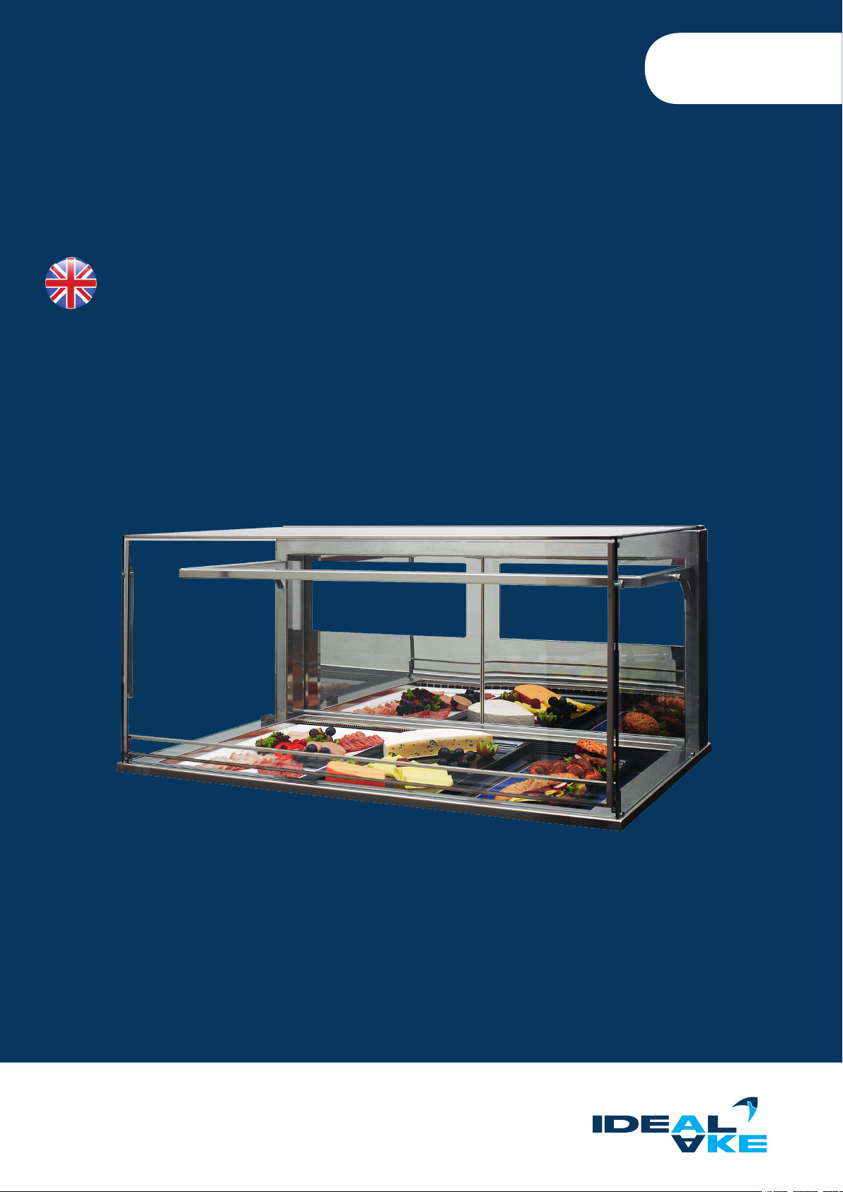
REFRIGERATED DISPLAY CASES
Self-contained or for remote refrigeration connection
Page 2

REFRIGERATED DISPLAY CASES
Information on this user’s manual
The user’s manual presented here applies to all builtin units of the refrigerated display case for assisted service type and is indepen-
dent of the dierent possible congurations regarding freestanding and gastronorm dimensions. Built-in units must be covered before
they are put into use keeping the technical requirements in mind.
The possibilities described in this user’s manual show the majority of congurations.
Due to custom designs, many other congurations of refrigerated display cases with convection cooling are still possible.
User’s manual & installation guide
Copyright © 2019, AKE Ausseer Kälte- und Edelstahltechnik GmbH.
All rights reserved.
This documentation is the translation of the original documentation.
No part of this publication may be reproduced, stored or in any way or transmitted or sent and published in any form without the prior
written permission of AKE.
Document: BH_Khlvitrinen_19A-EN
Revision: 19A
Application date: August 2019
Subject to technical modications | Valid from August 20192
Page 3
Contents
1. GENERAL INFORMATION AND SAFETY 4
1.1. FOREWORD 4
1.2. FLEXIBILITY 4
1.3. SCOPE 5
1.4. WARRANTY AND LIABILITY 6
1.5. SUPPORT 6
1.6. USED SYMBOLS AND SIGNAL WORDS 7
1.7. IDENTIFIER 7
1.8. GENERAL SAFETY INSTRUCTIONS 8
1.9. SPECIAL SAFETY INSTRUCTIONS FOR UNITS WITH PROPANE (R290) REFRIGERANT 8
1.10. PROPER USE 9
1.11. TARGET GROUP AND PRIOR KNOWLEDGE 9
1.12. REASONABLY FORESEEABLE MISUSE 10
1.13. RESIDUAL DANGERS 10
1.14. PERSONAL PROTECTIVE EQUIPMENT 12
1.15. TRANSPORT AND PACKAGING 12
1.16. DISPOSAL 13
2. TECHNOLOGY 14
2.1. EXPLANATION COMPONENTS 14
2.2. TECHNICAL SPECIFICATIONS 16
2.3. SAFETY INSTRUCTIONS ON THE UNIT 16
2.3.1. ELECTRICAL INFORMATION 17
2.3.2. REFRIGERATION-RELATED INFORMATION 17
2.4. ASSEMBLY AND INSTALLATION GUIDE 18
2.4.1. FIRST STEPS 18
2.5. INSTALLATION OF CONTROL BOX 19
2.6. CONDENSATE DISPOSAL (CONDENSATE) 20
2.7. VENTILATION AND DISCHARGE 20
2.8. DEFROSTING POSSIBILITIES 22
2.9. MALFUNCTIONS AND CAUSES 22
2.10. STATUS DISPLAYS AND ERROR MESSAGES ON THE DISPLAY 24
3. OPERATION - CARE 24
3.1. INITIAL START-UP 24
3.2. SWITCHING THE UNIT ON (BUTTON ASSIGNMENT) 25
3.2.1. UNITS WITH REFRIGERATED COUNTERS 26
3.2.2. TEMPERATURE SETTING 26
3.2.3. SENSOR CALIBRATION 27
3.3. STOCKING THE UNIT AND ADJUSTING THE HEIGHT OF THE SHELF 27
3.3.1. STOCKING THE CAKE DRAWER 28
3.3.2. STOCKING THE REFRIGERATED COUNTER 28
3.3.3. HEIGHT ADJUSTMENT OF INTERMEDIATE SHELVES 29
3.4. CLEANING AND CARE 30
3.4.1. CLEANING INTERVALS 30
3.4.2. CLEANING AGENTS 31
3.4.3. CLEANING THE EVAPORATOR 32
3.4.4. CLEANING THE GLASS 33
3.4.5. CLEANING OF THE CONDENSER (CONDENSER) 36
3.4.6. CLEANING THE NIGHT ROLLER BLIND 36
3.4.7. CLEANING THE REFRIGERATED COUNTER 36
3.4.8. CLEANING THE CAKE DRAWER 37
3.4.9. CLEANING THE BOTTLE SLIDER 38
4. SERVICE/MAINTENANCE 40
4.1. MAINTENANCE INFORMATION 40
4.2. PURCHASING SPARE PARTS 40
5. DECLARATION OF CONFORMITY 41
Subject to technical modications | Valid from August 2019 3
Page 4
REFRIGERATED DISPLAY CASES
1. GENERAL INFORMATION AND SAFETY
1.1. FOREWORD
Thank you for choosing one of our appliances. This product incorporates the highest technical standards with practical operating
convenience. With your unit, you will have a product that is state of the art with regard to operating safety for the start-up personnel,
the operator and users. The unit can be dangerous in the event of incorrect or improper use.
We point out dangers in Chapter 1 General Information and Safety and through safety information in the entire document.
The safety information and instructions in this document must be complied with. All personnel who install the unit, put it into
operation and operate it must have this document available and have read and understood it. Our unit requires correct installation,
start-up, operation and care. Non-compliance with the points mentioned above can lead to warranty, guarantee and product liability
exclusions, but also to damage and safety hazards. Always keep this document complete and in a perfectly legible condition. If
necessary, request it immediately from your supplier or operator, or download it from the homepage of the manufacturer
www.ideal-ake.at.
NOTICE
The manufacturer is not liable for technical or printing related deciencies of this document. In like manner, no liability
will be assumed for damage that is directly or indirectly attributable to the delivery, performance or use of this document.
NOTICE
The manufacturer reserves the right to change specications and the design at any time as part of ongoing product
improvement.
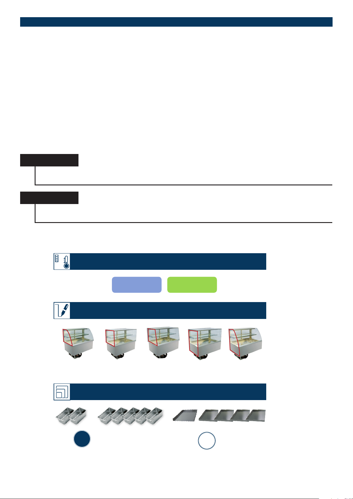
1.2. FLEXIBILITY
°C
CONFIGURATION POSSIBILITIES
COLD GREEN LINE
THE DESIGN (examples of closed display cases)
Round Squared
*) for insulated glass display cases on requeste
Inclined*)
PRO squared PRO round
THE SIZES IN USE
GN
GASTRO-
NORM
(2 to 5 trays up to max. 150 mm)
Subject to technical modications | Valid from August 20194
Gastronorm
EN
BACKNORM/
EURONORM
Euronorm
(1 to 4 baking trays)
Page 5
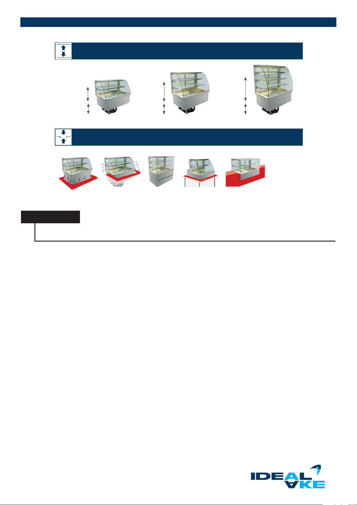
THE HEIGHTS (examples of closed display cases)
530 mm
370 mm *)
700 mm
370 mm *)
870 mm
370 mm *)
*) optional at 195 mm inner well possible
INSTALLATION VARIATIONS (examples of closed display cases)
Drop-in Slide-in Countertop PROFreestanding
NOTICE
Units with a base frame for combination with units (with height-adjustable feet) must be completely covered by the
customer.
1.3. SCOPE
This user’s manual applies to the models as given in the following as well as for local custom models and units with a pedestal.
Model designation:
Serie Gastro aabc-ddd-ee-f xx yy zzz
Serie Gastro und GREEN Ac-ddd-ee-f
Serie GREEN und GREEN FSV bc-ddd-ee-f xx yy zzz
Serie BAK bc-ddd-ee-f xx yy zzz
Serie BAK L und GREEN L Gc-ddd-ee-f
Serie BAK KSL und GREEN KSL bc-ddd-ggg-f
Serie Cold Flaps ee-f
Serie Khlturm KT-ddd
Serie BRILLANT KR ddd-f
Serie COOL BOTTLE ddd-f
Abbreviations:
aa: blank or HC (high capacity)
b: G (closed on customer side) or O (open) or A (countertop)
c: E (squared) or S (10° inclined) or R (round)
ddd: number between 50 and 200 (unit length)
ee: blank or number between 45 and 99 (height of glass enclosure)
f: E (self-cooled) or Z (self-contained)
ggg: Number between 50 and 200 (unit height)
xx: RG (Back wall closed)
yy: blank or EC (Easy Change) or KL (aps)
zzz: blank (drop-in installation) or PRO (for overhanging installation on the customer side)
Subject to technical modications | Valid from August 2019 5
Page 6
REFRIGERATED DISPLAY CASES
Model designation:
Sushi Tower -x yy
Cake Tower -x yy
Abbreviations:
: number between 53 and 78 (depth of the unit)
x: E (self-cooled) or Z (self-contained)
yy: blank or KL (aps)
NOTICE
The dimensions and weight specications of the unit are order-based and vary depending on the requirements. For
exact information, contact our customer service (see Chapter 1.5).
NOTICE
Please note that at least two persons are required to lift the unit, and at least four persons are needed as of a size of
3/1. Call in another person for spotting for the installation.
1.4. WARRANTY AND LIABILITY
Our „General Terms of Payment and Delivery“ apply. A guarantee claim and liability for personal and property damage is not possible
if it is attributable to one or more of the following reasons:
• improper use of the unit
• transport damage
• operation of the unit with defective safety components or with safety components that have not
been installed properly and are not operable
• non-compliance with the instructions in the user’s manual in connection with the correct installation, start-up, operation,
maintenance and assembly of the unit
• unauthorised mechanical or technical changes to the unit
• inadequate maintenance of used and wearing parts
• unauthorised repairs
• use of aggressive or caustic cleaning agents
• forces of nature or force majeure
Also excluded from the liability are:
• breakage of glass, breakage of plastic components or lighting xtures
• any damage that is demonstrably attributable to incorrect setting of the cooling control unit by an unqualied person
• damage or malfunctions due to incorrect assembly of the unit after cleaning
NOTICE
Units with the natural refrigerant propane (R290) must be installed in a safe environment that meets the requirements
of the respective directive. Exclusively electrical devices may be used inside the unit that are certied by the applicable
ATEX directive. The operator must be responsible for this.
NOTICE
The warranty claim may be lost if the given information is not observed.
1.5. SUPPORT
In the event of technical questions, contact your supplier or the manufacturer
AKE Ausseer Kälte- und Edelstahltechnik GmbH
Pichl 66
8984 Bad Mitterndorf
Austria
Subject to technical modications | Valid from August 20196
Page 7
NOTICE
If you contact our support, have the serial number of your unit ready. You can nd it on the rating plate or the “AKE
Certied” plate (see Chapter 1.7).
HINWEIS
If there are any malfunctions, switch the unit o and contact your supplier immediately.
1.6. USED SYMBOLS AND SIGNAL WORDS
DANGER
Imminent danger to the life of persons
Safety information with the Danger signal word indicates imminent danger to the life and health of
persons. Failure to observe these safety instructions can lead to death or serious damage.
WARNUNG
Danger of personal injury (serious injuries) and possibly property damage as well
Safety information with the Warning signal word indicates a dangerous situation that can have an impact on the health
of persons. Failure to observe these safety instructions can lead to serious injuries.
ATTENTION
Danger of personal injury (minor injuries) and possibly property damage as well
Safety information with the Danger signal word indicates a possibly dangerous situation. Failure to observe these safety
instructions can lead to minor or slight injuries
HINWEIS
This symbol with the comment Notice refers to supporting information for installation, operation or alternatively maintenance
and repair. Failure to observe this information can lead to property damage.
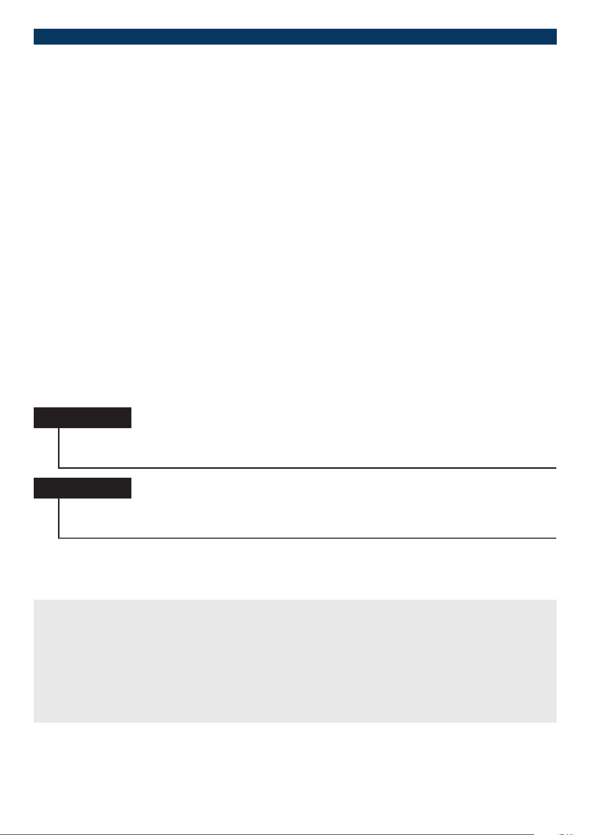
1.7. IDENTIFIER
The unit is clearly identied by the content of its rating plate.
The rating plate is found on the cover of the controller or in the
base near the control box
Subject to technical modications | Valid from August 2019 7
Page 8
REFRIGERATED DISPLAY CASES
1.8. GENERAL SAFETY INSTRUCTIONS
Generally, the following general safety provisions and obligations apply when working with the unit:
• Covers with warning signs may only be opened by specialists.
• The bottom and back side of the unit must not be cleaned with a water jet.
• The protective covers of the equipment may not be removed, otherwise there is a risk of injury.
• The controller may only be opened by a specialist.
• Air ows around the unit from improperly installed fans (e.g. air-conditioners) or draughts must be avoided in order to
ensure perfect operation of the unit.
• The ambient temperature must not exceed +25 °C, and the relative ambient humidity must not permanently exceed 60%.
• The unit is not suitable for operation in entrance and outdoor areas.
• The unit must be protected against sunlight.
• The products brought for presentation must be precooled with a core temperature of at least +5 °C or colder.
• Sharp objects must not be kept loosely in the unit, otherwise there is a risk of injury.
• All glass enclosures must be treated with the necessary care in order to prevent injuries from the glass breaking.
• Components and service uids may only be replaced with original parts.
• Do not store any combustible or explosive products in the unit or close to it.
• During the assembly or alternatively during installation, the unit must be covered adequately so that no contact with live
parts is possible.
• The installation environment must have a stable design in order to withstand the strains of everyday operation.
• It must not be possible to remove any coverings that are mounted during the installation without tools.
• After cleaning, the unit must be checked for loose connections, shearing points and damage. Remedy any
deciencies that are discovered immediately. Do not use the unit for any non-designated purposes.
• When topping up refrigerant, only the refrigerant given on the identication plate may be used. Topping up may only be
performed by authorised customer service. The lling quantity given on the rating plate must be followed.
• The unit must be installed away from heat sources in a low-dust and well-ventilated environment.
• Pushing or moving the units is not permitted. Units must be lifted to be transported or moved.
NOTICE
Technical changes to the unit may only be carried out by authorised specialists.
This applies in particular to work on the refrigeration system, electrical installation and mechanics.
Any change must be authorised by your supplier.
NOTICE
The unit must not be operated in the immediate vicinity of devices that generate heat or steam. This can
result in compressor damage, the formation of condensate on the glass, temperature control problems in the cooling area
and the like.
1.9. SPECIAL SAFETY INSTRUCTIONS FOR UNITS WITH PROPANE
(R290) REFRIGERANT
The following applies to units with propane (R290) refrigerant:
• In the event of the installation or combination with units as well as electrical/refrigeration system components that do
not comply with an R290 design in accordance with the respective directives, the unit must be covered and separated
from the adjoining units/components.
• The refrigerant circuit may be exclusively opened and the refrigerant extracted in a well ventilated room or outdoors.
Activities are to be carried out exclusively by authorised, qualied specialists who are trained for the
refrigerant propane (R290).
• Work on the refrigeration system is to be carried out exclusively by authorised, qualied specialists who are trained for
the refrigerant propane (R290).
• Exclusively electrical devices may be used inside the unit that are certied by the applicable ATEX directive
Subject to technical modications | Valid from August 20198
Page 9
• The cooling circuit and refrigeration system of the unit must not be damaged. This can lead to an unintentional
exothermic reaction of the ignitable gas/air mix.
• The ventilation openings of the cladding of the unit (including accessories) must not be blocked or covered.
In the event of a leak in the refrigeration system, this can lead to an unintentional exothermic reaction of the
ignitable gas/air mix.
• The ventilation openings on the front and back side of the appliance must be kept free. The minimum distances to
other units must be complied with. Make sure that the air circulation is unobstructed. In the event of a leak in the
refrigeration system, a blockage of the air circulation can lead to an unintentional exothermic reaction of the ignitable
gas/air mix.
• According to the standard DIN EN 378-1, the refrigerant propane is combustible and explosive (refrigerant group A3).
• The refrigerant propane (R290) can create an ignitable gas/air mix, which can trigger an exothermic reaction in a
critical mixing ratio with air and in connection with the respective ignition energy (ignition source).
1.10. PROPER USE
The units are intended specically for installation in food and dispensing counters. They are suitable for keeping food products and
beverages cold and presenting them at controllable temperatures (see catalogue and homepage). The units only serve to keep
food cold, but not to cool it down. The units must be operated in perfect condition. All existing covers and doors must be mounted
and closed during operation. The covers and doors may only be opened briey for stocking and removing products. The given
units are designed for climate class 3 according DIN EN ISO 23953. To save energy, we recommend switching o the units when
they are not in use outside of business hours. Before stocking the units, wait until the desired temperature is reached.
HINWEIS
I
It is mandatory for all the manufacturer’s specications to be complied with. Among others, these specications are the
ambient temperature, quality of the installation environment as well as the connections that are to be used.
Use in accordance with the intended purpose also includes observing the installation and operating guide as well compliance
with the inspection and maintenance conditions. Any other use requires the written approval of the manufacturer. Improper use
can endanger persons and result in damage to the system. The unit is operated via a control element that may only be used after
reading and understanding the documentation. Furthermore, liability and warranty claims are excluded in case of non-compliance
with proper use. The unit must be operated under the operating conditions described in the user’s manual.
1.11. TARGET GROUP AND PRIOR KNOWLEDGE
This documentation is intended for operating personnel in the area of gastronomy (e.g.: hotel chains, restaurants, catering) as well
for the installation personnel. The unit may only be operated by trained personnel who are to be dened by the operator.
Make sure that personnel intended to operate the unit have the following prerequisites:
• Operators may not be visually impaired, because they must be able to easily read the safety instructions on the unit and
the information in the documentation.
• Reading and understanding this documentation is a requirement, and the currently applicable regulations regarding
occupational safety and accident prevention must be complied with.
• Only instructed personnel may operate and clean the appliance. Only qualied personnel who have been
authorised by the manufacturer may perform mainte-nance and repair work
• Make sure without fail to observe the locally applicable safety regulations and regulations as mandated
by trade law.
To acquire the knowledge that is required to operate the unit, the following measures must be carried out by the operator
• product training
• regular safety instruction
This unit may be used by children as of 8 years old and moreover also by anyone with reduced physical, sensory or mental capabilities or a lack of experience and knowledge if they are supervised or have been instructed in connection with safe use of the unit
and the danger resulting from it. Children are not allowed to play with the unit. Cleaning and maintenance must not be carried out
by children without supervision.
Subject to technical modications | Valid from August 2019 9
Page 10
REFRIGERATED DISPLAY CASES
1.12. REASONABLY FORESEEABLE MISUSE
The units must not be used as follows
• No food may be cooled. The unit must not be lled with food that exceeds the stipulated core temperature (of +5 °C).
• Operation outside the specied temperature range is not reliably possible see catalog and website.
• No ventilation slits may be blocked or covered by food that touches the walls of the unit or blocks the air ow.
• The unit must not be operated outside of buildings. Protect the unit against direct sunlight.
• Units for food such as seafood, sh and muscles or the like must be designed with a higher grade of
stainless steel (V4A or AISI 316) or be upgraded with suitable GN trays.
• Glass covers and shelves must not be used as climbing aids or for storage.
• The refrigeration circuit may only be checked regarding a refrigerant leak by an authorised specialist.
The instructions for the use of propane (R290) must be complied with according to Chapter 1.9.
1.13. RESIDUAL DANGERS
Even with maximum care during the design and construction of the units and taking into consideration all safetyrelevant circum-
stances, there can still be residual dangers that were evaluated by means of a risk assessment. All the residual risks and safety
instructions from the risk assessment are listed in this chapter.
WARNING
Ignition danger from electrical or friction induced sparks and hot surfaces.
With refrigerant R290, an explosive gas/air mix can be created as a consequence of possible leaks in the refrigeration system.
The sparks from a vacuum cleaner or other electrical device may unintentionally ignite this mixture. Be aware that there are
no hot surfaces. Only use devices for cleaning, maintenance and service work that comply with the applicable ATEX directive.
WARNING
Danger of crushing when inserting or moving the units in the counter opening/cut-out.
When inserting units, be aware of the danger of crushing, also for other persons.
Manual lifting of the units must be carried out by at least four persons. These persons must be strong enough to be able to
carry the units Pushing or moving the units is not permitted! Call in another person for spotting if necessary. Wear protective gloves and safety shoes for installation and loading work.
ATTENTION
Danger of tripping in the entire area around the unit
Be aware of possible tripping hazards from cables/lines installed on the oor. Lines and cables must be installed safely by
the operator so that there is no tripping hazard.
WARNUNG
Danger of crushing as well as danger from falling objects when handling/aligning/positioning heavy individual components
When handling heavy objects, be aware of possible crushing dangers, also for other persons. If possible, use both hands
when you handle heavy objects. Get another person to help you if necessary. When handling/aligning/positioning heavy
individual components, protective gloves and safety shoes must be worn.
WARNUNG
Danger of being hit by the units during installation, cleaning and maintenance work
Be aware of possible dangers of being hit by the unit.
WARNUNG
Danger of crushing/cutting when handling the evaporator box
When lifting and reinserting the evaporator box, use the metal rod intended for that purpose. When lifting the evaporator
box, make sure that it is lifted far enough until the locking tabs snap into place automatically. Hold the evaporator box on
the metal rod rmly or alternatively in position before unlocking.
Subject to technical modications | Valid from August 201910
Page 11
WARNING
Danger from leaking refrigerant from a damaged evaporator
No pointed objects may be used for cleaning the evaporator ns. The evaporator ns may only be cleaned by products
specied by the manufacturer.
WARNING
Danger of crushing/cutting when moving the sliding or hinged doors
Use the handles designated for that purpose when opening and closing the sliding doors. When closing the sliding doors,
do not reach between the side sections of the sliding door and the unit. Do not reach into the area between the bottom
side of the angle trim and the top edge of the sliding door. Make sure that the angle trim is attached and screwed together
properly. The same thing applies to hinged doors. Be very careful when handling glass.
WARNING
Danger of crushing/cutting when moving the glass cover or front glass
Wien lifting the glass cover, use the small handle strip designated for that purpose. At least two persons are needed to
open the glass cover or front glass. Close the glass cover and front glass carefully, and watch out for dangers of being
crushed on the glass cover and front glass. Be very careful when handling glass.
WARNING
Various dangers during the disposal of various refrigerants
Wear protective gloves and eye protection during the disposal of refrigerants (propane, R404A, R134A etc.). Working with
open ames is forbidden during the disposal of refrigerant. Dispose of the refrigerant properly and in an environmentally
compatible way.
WARNING
Various dangers during the disposal of damaged parts/components
When disposing of damaged parts/components wear protective gloves. Dispose of damaged parts/components properly
and in an environmentally compatible way.
WARNING
Electrical dangers
Make sure that the mains connection of the unit is not damaged. In the event of damage, it must be replaced by the distributor or its customer service to avoid hazards..
ATTENTION
Danger of slipping due to condensate leaks.
Be aware of the possible danger of slipping in the area around the unit due to leaking liquids. During the installation, make sure that the siphon is installed properly and does not leak.
ATTENTION
Danger of crushing when sliding in the manual condensate tray (modeldependent)
Use the handle strip designated for that purpose when sliding in the manual condensate tray. Make sure that the condensate tray is pushed into compressor compartment completely.
Subject to technical modications | Valid from August 2019 11
Page 12
REFRIGERATED DISPLAY CASES
1.14. PERSONAL PROTECTIVE EQUIPMENT
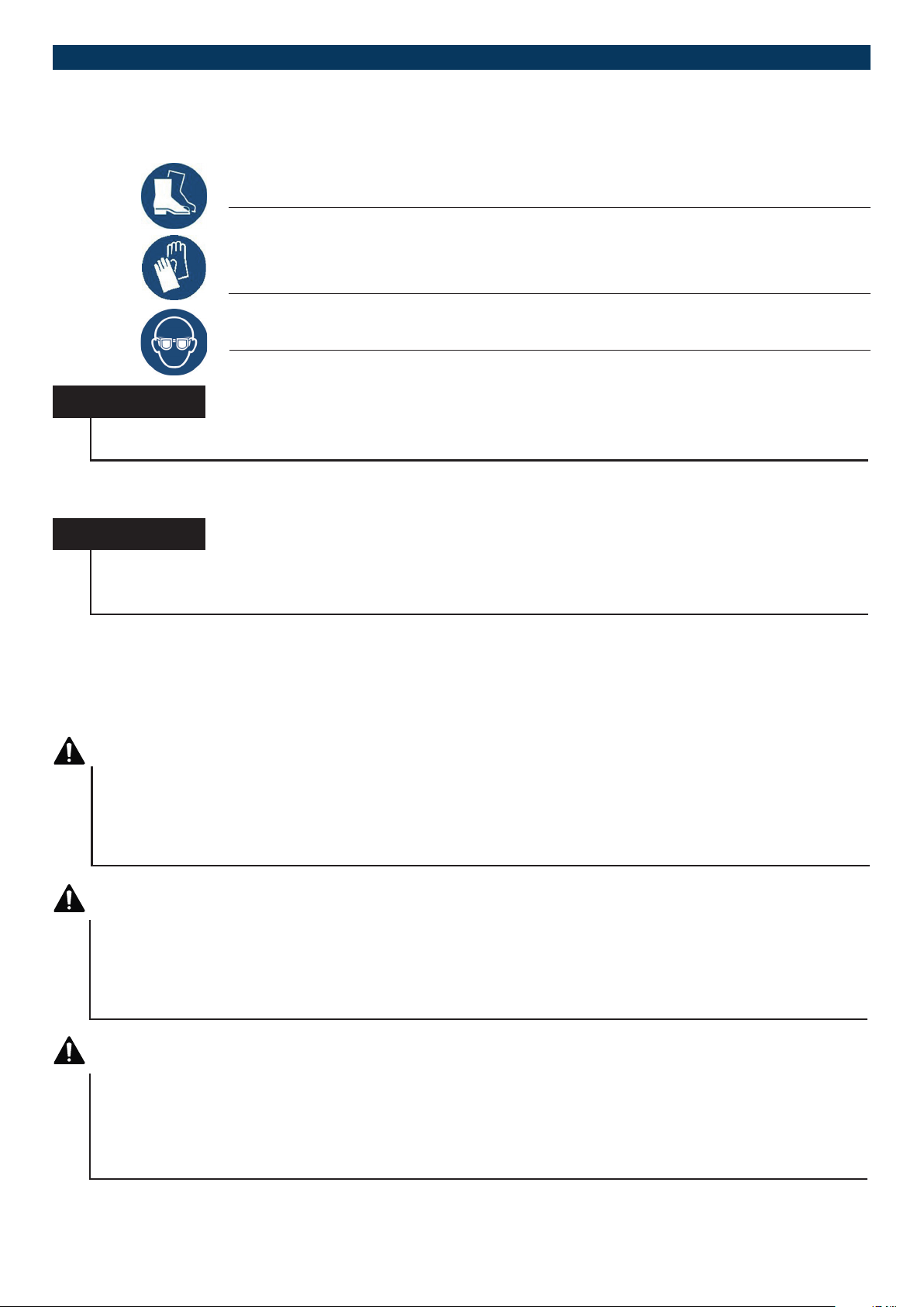
The following protective equipment must be worn for installation, dismantling and maintenance work:
Wear safety shoes for installation and loading work.
Wear safety gloves during installation and loading work and when working with refrigerant according to EN 378-3.
Wear eye protection for disposal of the refrigerant from damaged assemblies/components.
NOTICE
When cleaning the unit, wear the respective protective equipment stipulated by the manufacturer of the cleaning agent
being used.
1.15. TRANSPORT AND PACKAGING
NOTICE
Only transport and store all units in the position of use (horizontal). Units with propane as a refrigerant or other combustible and explosive refrigerants must be transported and handled by observing the points given in Chapter 1.9. Among
other things, the safety instructions given in Chapter 1.8 must be complied with.
The design of the packaging is dependent on the submission of the proposal and is designed individually by agreement. By default, the units are transported with wood cladding. This cladding protects the units against major damage. Glass shelf supports
are secured on the left and right with L-shaped transport locks. Components made of glass are wrapped additionally with packaging material. Moving parts as well as glass shelves are given an additional shell of packaging material. All parts are positioned
and taped safe for transport inside this wood cladding.
WARNING
Danger from falling objects when transporting the units and their components
Use adequately dimensioned lashing and clamping devices. When securing the load, observe the per missible vehicle
provisions. Local road regulations must be complied with. Any load lifting equipment that is used, e.g. forklifts, must be
adequately dimensioned. During lifting processes, make sure that nobody is underneath loads being transported while
raised. The unit may only be transported upright.
WARNING
Danger of crushing on stationary structural elements (walls, other machines) when positioning the units, as well as
danger of crushing between the pallet and ground when putting the unit down
Keep yourself and other persons away from the hazardous area. Call in another person for spotting if necessary. When
putting units down, be aware of the danger of crushing for other persons. Wear protective gloves and safety shoes for
installation and loading work.
WARNING
Danger from falling objects when lifting as well as unpacking the units
When removing the wood cladding, be aware of possible dangers from wooden parts that snap out. Get another
person to help you if necessary. The unit must be lifted with suitable load lifting equipment, e.g. a forklift. Manual lifting
of the unit must be carried out by at least four persons. These persons must be strong enough. Wear protective gloves
and safety shoes for installation and loading work.
Subject to technical modications | Valid from August 201912
Page 13

In case of a return shipment, the unit must be packed in the original packaging or in the same way, in a suitable manner for transport. Furthermore, the unit must be delivered unused, undamaged and complete. The return shipment must be commissioned and
paid for by the customer. Information on correct disposal of the packaging material can be found in Chapter 1.16.
NOTICE
All units must only be transported and stored in the position of use (horizontal). To make damage that is caused
during loading, transport and unloading traceable, all units with a glass enclosure are equipped with a socalled
“Shockwatch® 2”. This tool makes it possible to determine at which point of the delivery chain a product is damaged
in order to clarify transport damage. Information on the ShockWatch® concept is stored in the QR code
(see Chapter 4.1).
1.16. DISPOSAL
WARNING
Various dangers when disposing of refrigerants
Wear protective gloves and eye protection during the disposal of refrigerants (propane, R404A, R134A etc.). Working with
open ames is forbidden during the disposal of refrigerant. Dispose of the refrigerant properly and in an environmentally
compatible way.
WARNING
Various dangers during the disposal of damaged parts/components
When disposing of damaged parts/components wear protective gloves. Dispose of damaged parts/components properly and
in an environmentally compatible way.
NOTICE
Please note that some of the components of the unit are electronic parts. Therefore disposal using
public waste management companies is not possible. Check your obligations in accordance with the
national WEEE provisions. Sorted disposal is mandatory in any case.
Subject to technical modications | Valid from August 2019 13
Page 14
REFRIGERATED DISPLAY CASES
CUSTOMER SIDE
Einlegeboden UKW
Einlegeboden UKW
Einlegeboden UKW
323
531
Auflagestege
2. TECHNOLOGY
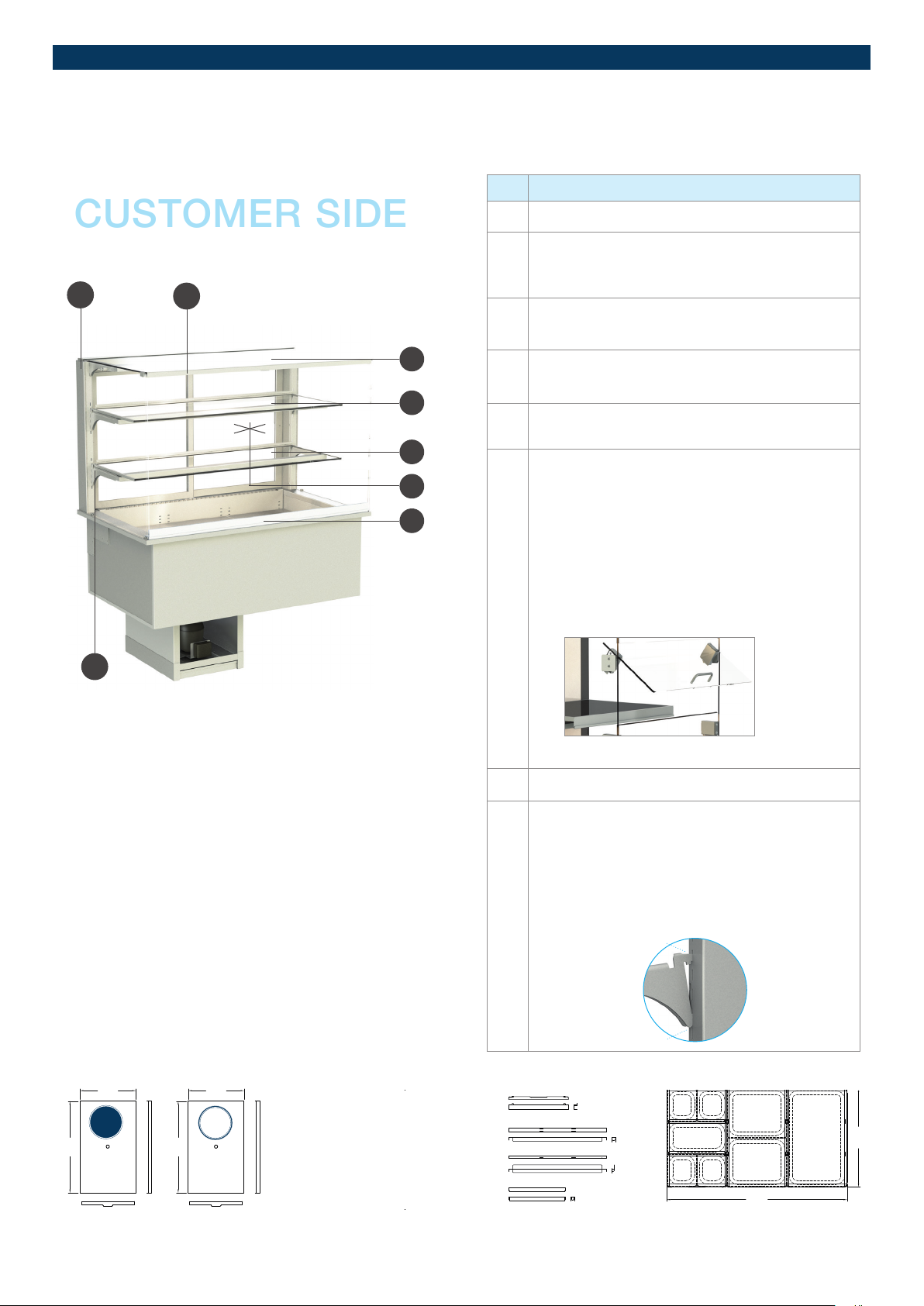
2.1. EXPLANATION COMPONENTS
1
2
3
4
5
6
7
No. Name
1 Frame support
Position of night roller blind in roller blind box
2
(model-dependent in mechanical or electrical desig
with incremental settings)
3 Glass cover
(with handle strip, model-dependent with gas dampers)
4 Glass shelf
(level 2)
5 Glass shelf
(level 1)
6 Front glass
(Panoramic window can be folded forward, modeld
pendent with safety cord)
Possibility:
- Easy change function
(Choice of open or closed operation)
- soft-close removal aps
(SoftClose)
8
1
multifunctional height-adjustable, individual components:
531
323
GN
GASTRO-
NORM
531
600
400
323
EN
BACKNORM/
EURONORM
Lengthwise bar, middle
Lengthwise bar, side
Einhängeleiste
Hook-in strip
Längssteg
Mitte
Längssteg
seitlich
Quersteg
Crossbar
7 Tilting structure
Shelf support
8
Possibility:
- choice of inclined/straight
position through hooking
in the top tab
- choice of height adjustment
± 25 mm through hooking inr
the top and bottom tab
Top tab
Bottom tab
GN
1/6GN1/6
GN 1/3
GN
1/6GN1/6
GN 1/2
GN 1/2
980
GN 1/1
535
Subject to technical modications | Valid from August 201914
Page 15
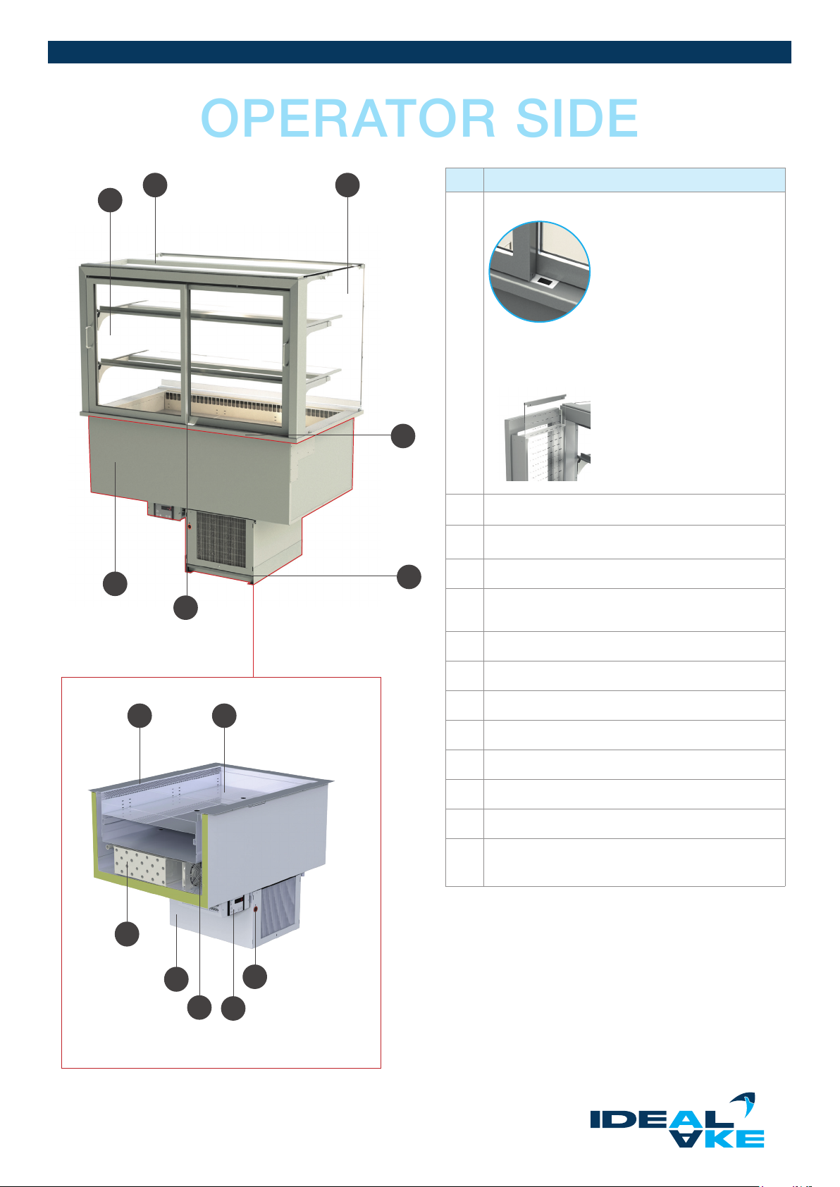
OPERATOR SIDE
2 3
1
No. Name
1 sliding doors with handle and lock
Possibility:
- sliding doors model-dependent
with Lexan-airguide
4
2 Lighting support (with lamp)
3 Side glass, right
6
1
7
8
5
4 Cutting board (removable)
5 Condensate tray
possibilities, see Chapter 2.2
6 Base with cake drawer or drawer (model dependent)
7 Ventilation plate
8 base shelf
9 Inspection glass
1
CUSTOMER SIDE
10 Control unit (incl. display)
11 Evaporator fan
12 Compressor compartment
13 Evaporator (incl. evaporator plate), can be folded up
and rinsed
2
(including condensing unit)
13
12
9
11
10
2
Remote refrigeration not available,
Waterloop dierent conguration
Subject to technical modications | Valid from August 2019 1 5
Page 16
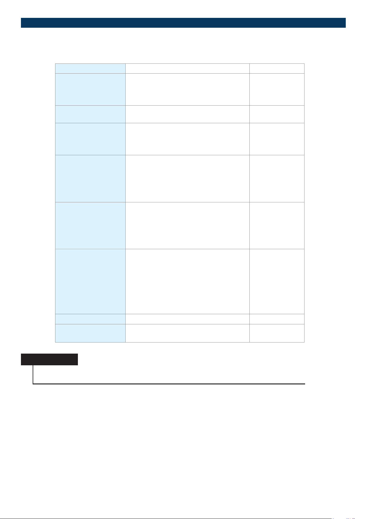
REFRIGERATED DISPLAY CASES
2.2. TECHNICAL SPECIFICATIONS
Protection class Protection class I Earth connection EN 61140
Performance data according to rating plate or
• homepage
• catalogue
• oer
Noise data < 70dB(A) (closed units) IEC 60335-1
Drinking water connection
Wastewater, condensate
Condensate • via siphon directly into the onsite
Materials • Stainless steel
Vendor components • Compressors
The distributor/operator is responsible for this Recommended:
sewer system (DN32)
• via the hot gas evaporation
• via the condensate tray:
- manual emptying
- electric condensate heater
- 1.4301 (well, body)
- 1.4016 (compressor
compartment/outer shell)
- 1.4404 (custom design)
• Copper tubes (refrigeration circuit)
• Evaporator
• Gas dampers (model dependent)
• Glass (model dependent)
• Electric lines and assembly materials
(cable, cable ties,...)
• Control box (PCB, display,...)
IEC 60335-2-89
IEC 61770:2008
OENORMEN
1717:2008-04-01
Insulating material LAMOLTAN® polyurethane rigid foam system
Glass Tempered safety glass
8mm and 6 mm
EN12150-2:2004
NOTICE
Due to the use of highquality and longlasting materials as well as vendor components, a long service life
is to be expected with regular care and maintenance.
2.3. SAFETY INSTRUCTIONS ON THE UNIT
Safety instructions are attached to the unit. They must be followed under all circumstances. If the safety markings start to blister
or become damaged over the course of the service life of the unit, then they must be replaced by new signs without delay. The
legibility and completeness must be checked at regular intervals.
Subject to technical modications | Valid from August 201916
Page 17
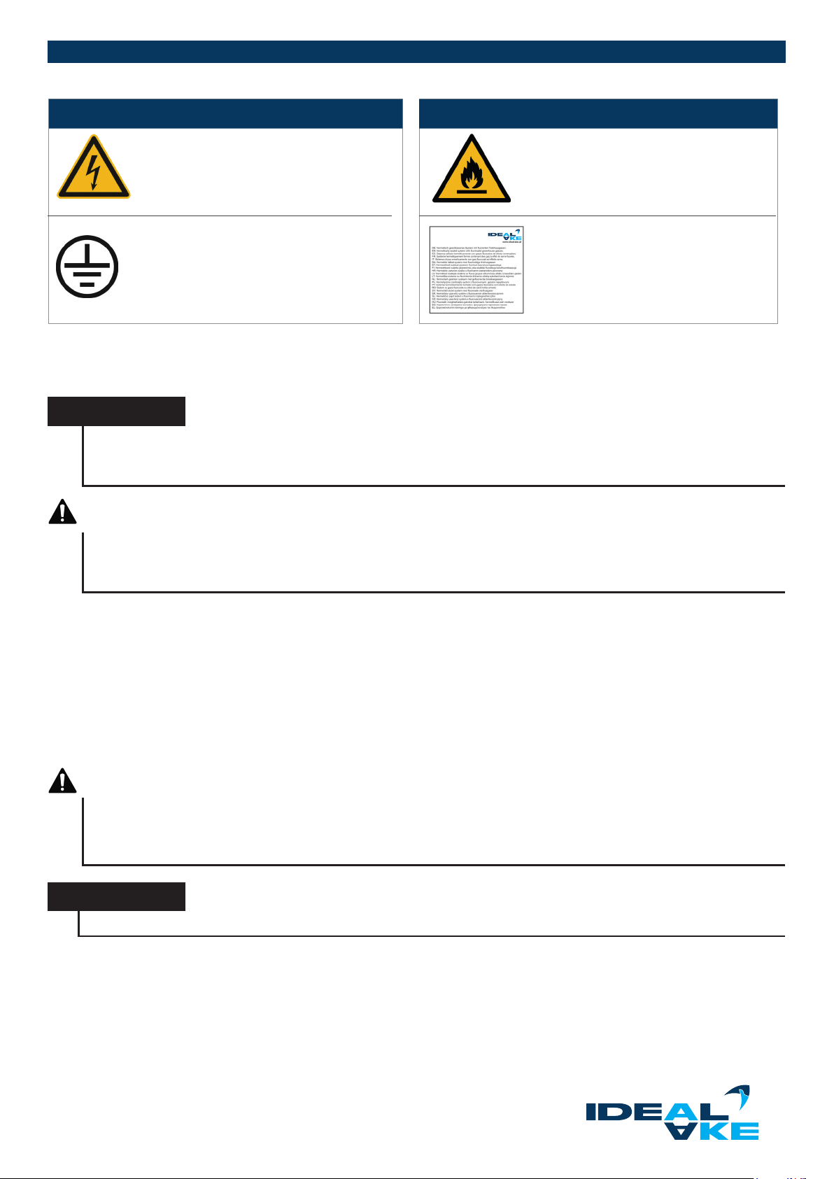
Pictograms Description Pictograms Description
Warning - electrical hazard
Protection class I Earth connection
Warning – inammable substances
(refrigerants of class A2L, A2, A3, B2L,
B2 and B3)
F-gas marking
(in accordance with ordinance
(EC) no. 517/2014).
2.3.1. ELECTRICAL INFORMATION
The units are completely equipped and installed electrically.
NOTICE
The cooling controller is completely set and ready for operation. After completion of the installation, check parameter
H12 (calibration of return air sensor). The cooling controller must be carried out by a authorised expert according to
the enclosed programming guide.
GEFAHR
Danger from electrical voltage on live components
The electrical connection must be carried out by a specialist and comply with the applicable standards, and safety
regulations.
Connection of the unit
Self-contained units are delivered with a 1.5 meter long power cord with an earthing contact plug as a standard feature. It is
connected to an AC power grid with a nominal AC voltage and frequency of 230 volts 50 Hz (country dependent with 115V 60Hz,
120V 60Hz, 220-240V 50-60Hz). The electrical supply line must be protected with a 16 A fuse (trip characteristic “C”).
Possibility of disconnection from the power grid
If a plug connection is used for the mains connection, then the power outlet must be easily accessible to be able to disconnect the
unit from the power grid if need be (cleaning, maintenance work). If direct wiring is used, then a means of disconnecting the unit
from the power grid must be provided.
DANGER
Danger from electrical voltage on live components
The mains voltage and frequency must match the values given on the rating plate. It is not permitted to connect to any
other voltage, type of current or frequency. The relevant local safety regulations must be observed.
NOTICE
Units without their own cooling unit have to be installed exclusively by a specialised refrigeration rm.
2.3.2. REFRIGERATION-RELATED INFORMATION
All units are equipped with coated n coil evaporators. The connection pipes lead out downwards through the foamed
refrigerated well. All pipes are installed and insulated. Units that are congured with gas dampers for the opened position of the n
coil evaporator must be checked monthly to make sure they work (model dependent).
Subject to technical modications | Valid from August 2019 1 7
Page 18
REFRIGERATED DISPLAY CASES
WARNING
Various dangers when disposing of refrigerants
Wear protective gloves and eye protection during the disposal of refrigerants (propane, R404A, R134A etc.). Working with
open ames is forbidden during the disposal of refrigerant. Dispose of the refrigerant properly and in an environmentally
compatible way.
WARNING
Various dangers during the disposal of damaged parts/components
When disposing of damaged parts/components wear protective gloves. Dispose of damaged parts/
components properly and in an environmentally compatible way.
Self-contained units
With self-contained units, the pipework is rmly connected to the refrigeration unit, and the refrigeration
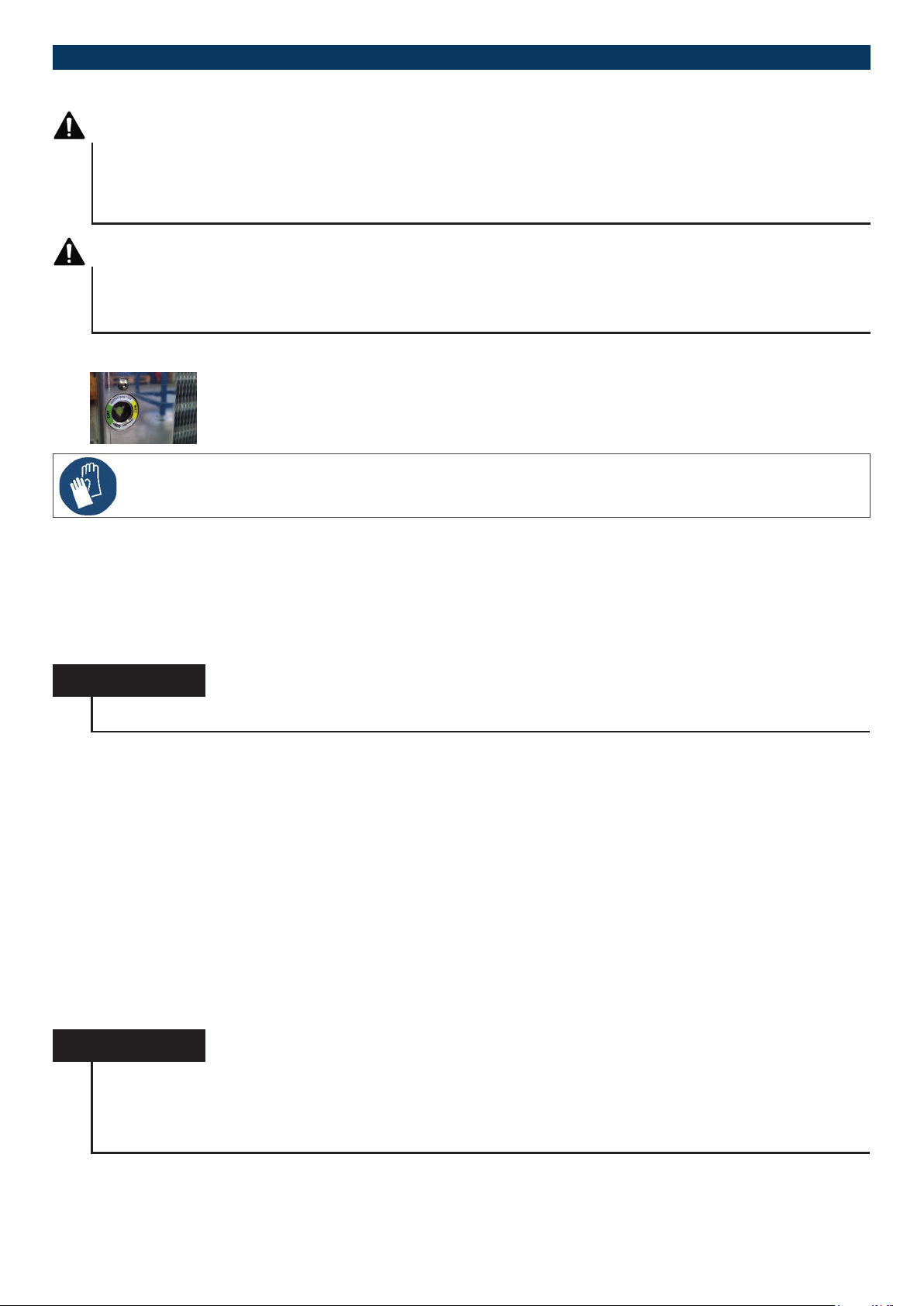
circuit is lled with refrigerant. Display cases with expansion valves and as of a specic size have an inspec
tion glass with a moisture indicator (for checking in case of
service). It is located beside the condenser.
For services purposes, the refrigeration system including the stainless steel housing can be pulled out to the front.
Do not pull or damage the lines that are behind it!
-
Remote refrigeration units
Remote refrigeration units are designated for connection to an existing refrigeration plant provided by the customer. The copper
tubing is insulated and leads out downward through the foamed refrigerated well with convection cooling. The evaporator is equipped with an expansion valve for the desired refrigerant and lled with dry nitrogen. Solenoid valves, lter dryers and possibly also
back pressure regulators must be installed by the customer. The specied evaporation temperatures as well as condensing temperatures must be kept constant. Steam components must be avoided in front of the expansion valve.
NOTICE
Solenoid valves, lter dryers and possibly also back pressure regulators must be installed by the customer.
Connection work
All work, installations, deliveries and services may only be carried out by authorised refrigeration companies and qualied specialists. The state of the art, relevant legal provisions, regulations and guidelines of government agencies, professional and trade
associations must be complied with. The installed refrigeration system must be put into operation, and a functional and safety test
performed. The report must be submitted to the client.
2.4. ASSEMBLY AND INSTALLATION GUIDE
In this chapter, you are given important information on the assembly and use of the units.
2.4.1. FIRST STEPS
Taking possession
Check whether the unit has any transport damage and write down the damage that you discover on the transfer papers from the
freight forwarder as well as on your form. Have the damage conrmed.
NOTICE
To make damage that is caused during loading, transport and unloading traceable, all units are equipped with a socal-
led “Shockwatch® 2”. This tool makes it possible to determine at which point of the delivery chain a product is damaged in order to clarify transport damage. Information on the ShockWatch® concept is stored in the QR code
(see Chapter 4.1).
Subject to technical modications | Valid from August 201918
Page 19
If the damage is only discovered after unpacking, then you are required to report it immediately in writing. It is advisable to notify your
supplier by phone in advance. You need the following to remove the transport packaging:
• at least two persons
• Tools:
- cordless screwdriver or Philips screwdriver for screw size 3.9x45 mm
- cutting tool (scissors or knife)
NOTICE
Your claim to compensation for the damage is lost if you do not report transport damage in good time.
(according to GTCs).
Setup
All requirements placed on the installation site according to Chapter 1.8 must be followed in order to ensure ecient and safe
operation.
NOTICE
Avoid placing the unit near any equipment that produces a lot of steam. This can lead to heavy icing of the evaporator
and condensate on the glass and other performancereducing as well as unwanted adverse eects.
NOTICE
Correct installation and trouble-free operation is a requirement for putting the unit into operation. The installation must
comply with the local electrical, safety and hygiene regulations.
Preparation
You need the following to install the unit:
• at least two persons
• Tools:
- adjustable wrench or pipe wrench (for units with a pedestal)
- spirit level
The installer is responsible for the safe condition or alternatively maintenance of the unit. Make sure that the appliance cladding
and counters are prepared in accordance with the technical specications. The size of the installation openings for the respective
model can be found in the current product catalogue under “Technical Data”. Protect the surfaces of the unit and the base against
any damage during the installation
NOTICE
It is necessary for the base to be level in order to enable the condensate to drain o. Test whether the water on the
inside of the well can also drain.
All work, installations, deliveries and services may only be carried out by authorised refrigeration companies and qualied specia
lists. Electrical installations may only be carried out by a specialist. You must ensure that suitable personnel and tools are available
to prevent damage and injuries.
-
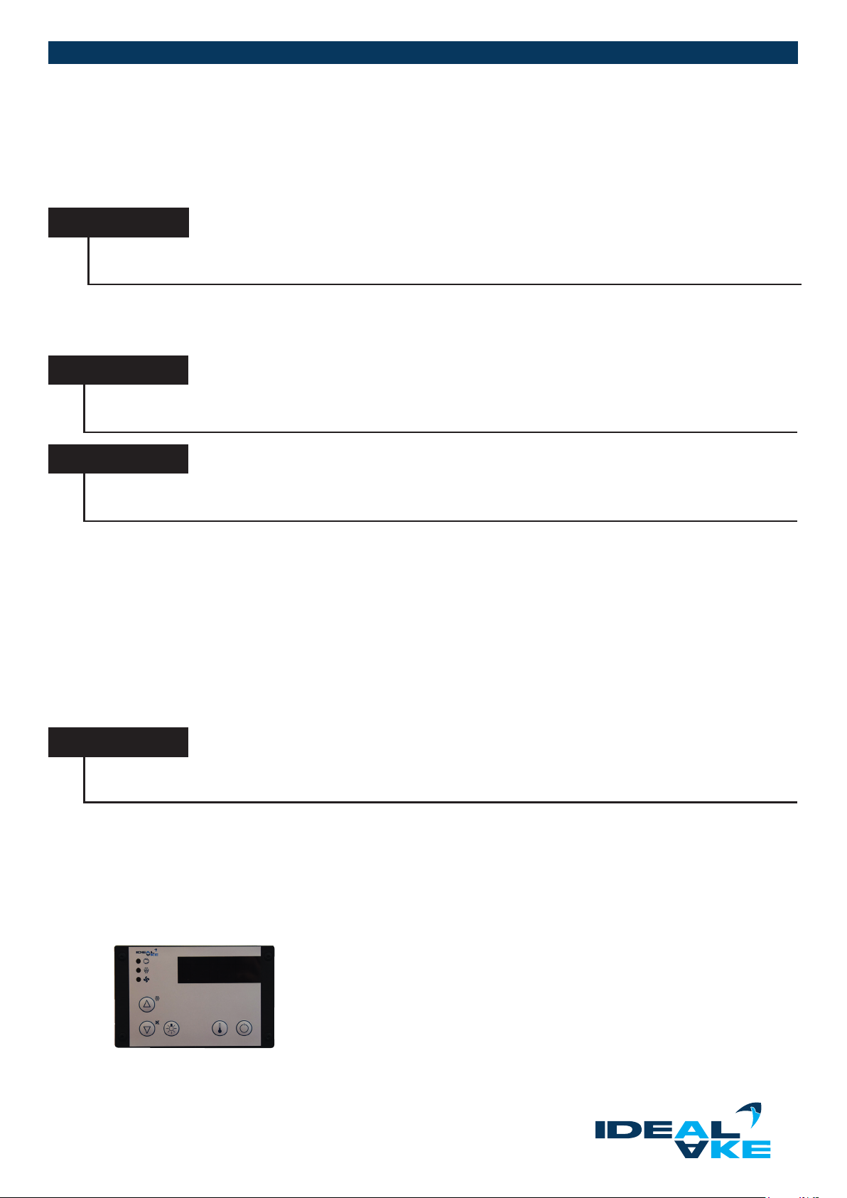
2.5. INSTALLATION OF CONTROL BOX
The control box is located on the base of the unit. With remote refrigerated units, the control units is enclosed loosely.
Each control unit consists of the display (control panel) and the power
electronics (PCB) that is built into the housing of the control box. The digitial display
is connected via a 2 m SUB-D cable with the PCB (>2m data transfer erroneous). This
digital display can be removed and mounted separately up to a maximum of
1,5 meters away from the PCB box.
Subject to technical modications | Valid from August 2019 19
Page 20
REFRIGERATED DISPLAY CASES
NOTICE
The cut-out required for the display is 87.5 x 56.5 mm. For the button assignment, see Chapter 3.2.
2.6. CONDENSATE DISPOSAL (CONDENSATE)
The condensate can be disposed of in a variety of ways (see table in Chapter 2.2).
WARNING
Danger from leaking water from an open hot gas evaporation or improperly installed condensate tray
During the installation as well as operation of the unit, pay attention to a properly pushed-in condensate tray and comple-
tely closed hot gas evaporation. Manually lifting the units can lead to loosening of the locking mechanism of the hot gas
evaporation and hence to the condensate leaking out. This must be checked after the installation and before putting the
unit into daily operation. Wear safety gloves for the installation and inspection.
Via siphon directly into the sewer system
Units that are operated with remote refrigeration are equipped at the factory with odour traps (siphon) so that only the wastewater
connections or external condensate trays have to be installed in accordance with the local conditions. It must be ensured that was
tewater cannot get back into the refrigeration point.
-
Fully automatic condensate evaporation
Self-contained units (model-dependent) are equipped with fully-automatic condensate evaporation.
NOTICE
Units with hot gas evaporation have a condensate tray. They may only be operated with the condensate tray pushed in
and completely closed.
NOTICE
The wastewater installation may only be carried out by authorised specialists.
NOTICE
Electric condensate evaporation trays generate heat and moisture. To prevent damage to the condenser, they must be
installed at the greatest possible distance. The installation and assembly guide of the condensate tray can be found in
Chapter 4.1 under the QR code that is given there.
2.7. VENTILATION AND DISCHARGE
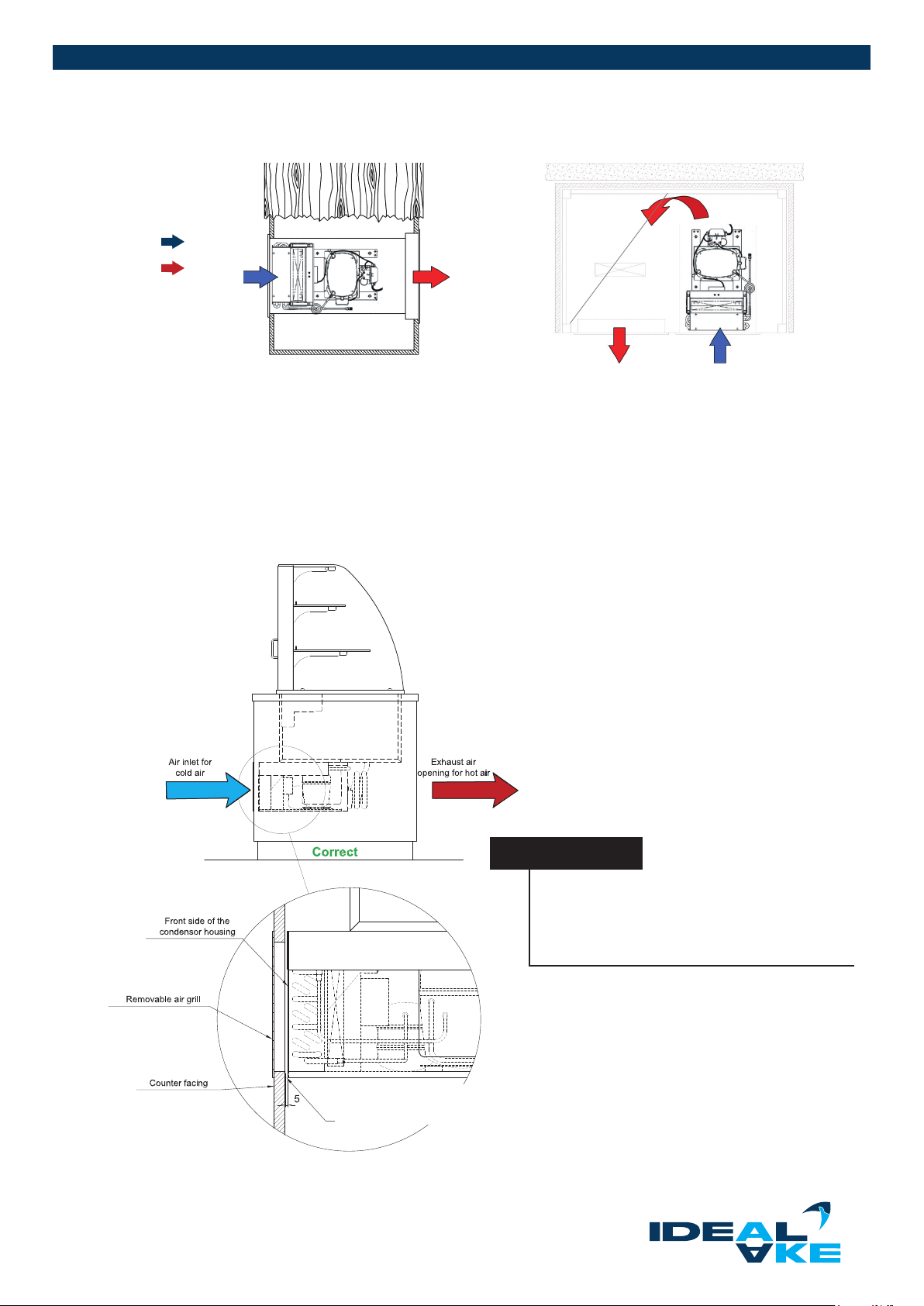
By default, the units are delivered with incoming air on the operator side and outgoing air on the customer side. We
recommend having the exhaust air outlet on the customer side (see variant 1). If an exhaust air outlet on the customer side
is not possible, then the exhaust air must be congured to be on the side or on the operator side (see variant 2). Make sure
that the exhaust air is not directly drawn back in, in order to ensure perfect operation.
ATTENTION
Reduction of the cooling capacity or destruction from overheating of the refrigeration unit.
The air circulation openings of the refrigeration unit must not be blocked or obstructed! The airow must not be
interrupted or impaired. The ventilation grilles must have at least the 1.5-x cross-section of the condenser surface
Congure the openings of the ventilation grille with ns.
Subject to technical modications | Valid from August 201920
Page 21
Variant 1
Variant 2
supply air
exhaust air
air deector plate
Compressor: The compressor pumps the gaseous refrigerant through the cooling system.
Condenser/fan/blower: The fan draws in cold room air and that way cools the compressor and the hot gas in
the condenser.
Condenser: This is a heat exchanger in which the extracted heat of the cooling area is released back
into the circulating air. Gaseous refrigerant is liqueed again through the heat release.
All self-contained units have a pull-out compressor housing. That way, you have the
possibility to position the condenser on the ventilation grille of the air inlet and avoid air
circulation
NOTICE
Prevent the hot exhaust air from being drawn
back into the compressor compartment. The air
opening of the covering must be less than 5mm
away from the condenser.
Small gap between condensor housing an facing:
Clos this gap with a sealing tape!
Subject to technical modications | Valid from August 2019 21
Page 22
REFRIGERATED DISPLAY CASES
2.8. DEFROSTING POSSIBILITIES
Automatic defrosting
Defrosting is handled automatically with the electronic thermostat. As set at the factory, the unit starts defrosting at regular intervals
(model dependent) closed display cases every three hours, self-service display cases every two hours. The duration of the defrosting phase is limited by the defrost sensor. During this time, the centre LED illuminates on the left display. Cooling mode starts
automatically when defrosting is completed
Manual defrosting
Defrosting can be initiated at any time by pressing the UP button (as described in Chapter 3.2). If the LED starts ashing after
pressing the UP button, the entry has been recognised. Defrosting starts automatically after several minutes. The respective LED
illuminates continuously during defrosting.
2.9. MALFUNCTIONS AND CAUSES
Check the points listed below and contact your supplier or specialist dealer if this does not resolve the problem.
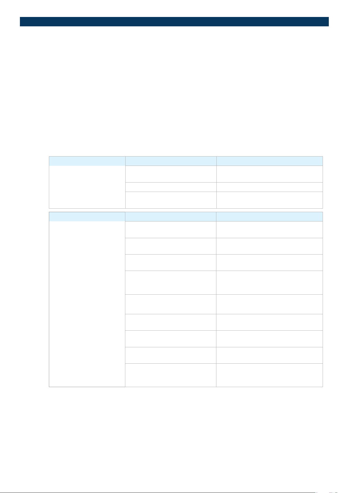
FAULT POSSIBLE CAUSE REMEDY
The unit doesn‘t work. Power supply disconnected Check the t of the
earthing contact plug (power plug)
No power to the socket Check whether the fuses are intact
Electronics set incorrectly or
display dark
Contact an authorised service technician
FAULT POSSIBLE CAUSE REMEDY
The products do not reach
the desired temperature.
One or more doors are open. Close doors, check temperature
(after 30 minutes)
The ventilation slits in the unit are
covered or blocked with goods.
Evaporator tray inserted incorrectly. Insert the evaporator tray with the opening
Ventilation and discharge
inadequate.
Temperature on the display diers
from the measured temperature
Too much or too warm food Precool the products (see Chapter 1.8) un
The target temperature is too high Set the target temperature value
The ambient temperature in the
room is too high (more than 25 °C).
A draught from the outside is inter
fering with the circulation of the cold
air (mainly with open units).
Uncover the ventilation slits
(see Chapter 3.3)
at the top as shown in Chapter 3.4.3
Ensure ventilation and discharge as given
in Chapter 2.7. If necessary, contact an
authorised service technician.
Contact an authorised service technician
(sensor calibration necessary).
cover the air openings (see Chapter 2.7)
(see Chapter 3.2.2)
Adjust the room air-conditioning
(see Chapter 1.8).
-
Choose installation location without a
strong draught; follow requirements given
in Chapter 1.8.
-
Subject to technical modications | Valid from August 201922
Page 23
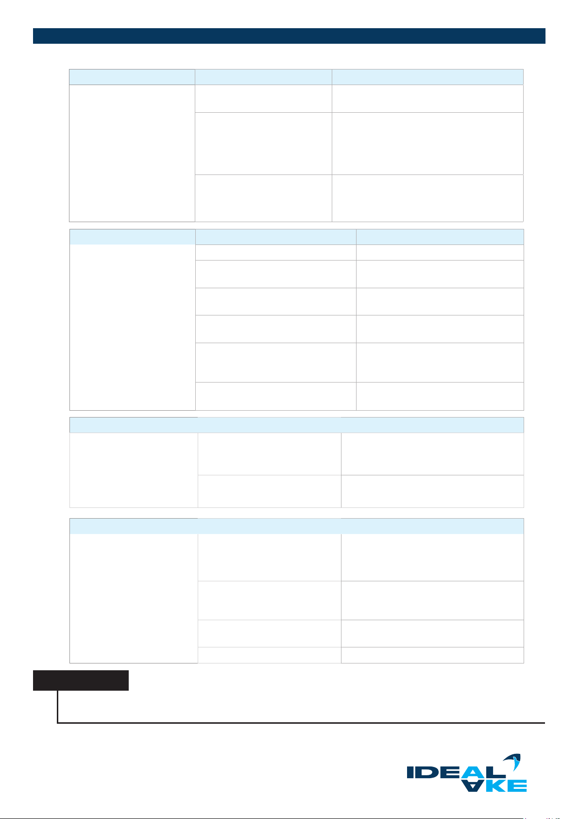
FAULT POSSIBLE CAUSE REMEDY
Condenser fouled Clean with vacuum cleaner
(see Chapter 3.4.5)
Evaporator heavily iced Initiate manual defrosting
(see Chapter 2.8) or switch the unit o for
several hours. Monitor: Visual
inspection of whether evaporator is free of ice.
Otherwise repeat defrosting.
Refrigeration unit/refrigeration
components malfunction, refri
geration circuit defective
FAULT POSSIBLE CAUSE REMEDY
The evaporator ices up
constantly.
The fans aren’t running. Contact an authorised service technician
Air circulation impeded in the unit Uncover the ventilation slits
Evaporator tray inserted incorrectly. Insert evaporatory tray with the opening
Doors open too long Only open the doors as long as
Too much warm or alternatively moist
ambient air is drawn into the cooling
chamber
Defrosting parameters incorrect/defrost
sensor defective
Contact a service technician
-
(see Chapter 3.3)
up like in Chapter 3.4.3.
absolutely necessary
Follow requirements according to
Chapter 1.8.
Contact an authorised service technician.
FAULT POSSIBLE CAUSE REMEDY
The lighting doesn’t work
correctly.
FAULT POSSIBLE CAUSE REMEDY
Condensation on the glass Too low temperature in the unit Press the SET button, units without
Light not switched on Press the Light button on the control unit for
around one second (see Chapter 3.2). If this
doesn‘t help, contact a service technician.
The entire lighting/one LED
has failed
Too high ambient temperature/
too high air humidity
Neighbouring units giving o heat Check the installation situation. If necessary,
Fan speed too high Contact an authorised service technician.
Contact an authorised service technician.
insulating glas
≥ 4 to 5 °C (see Chapter 3.2).
+25 °C ambient temperature and 60 %
should not be exceeded. – If possible,
switch on the air-conditioner.
contact an authorised service technician.
NOTICE
The manufacturer is not liable for any loss of product, even if the unit is still under guarantee. We recommend checking
the temperature of the unit every six months.
Subject to technical modications | Valid from August 2019 23
Page 24
REFRIGERATED DISPLAY CASES
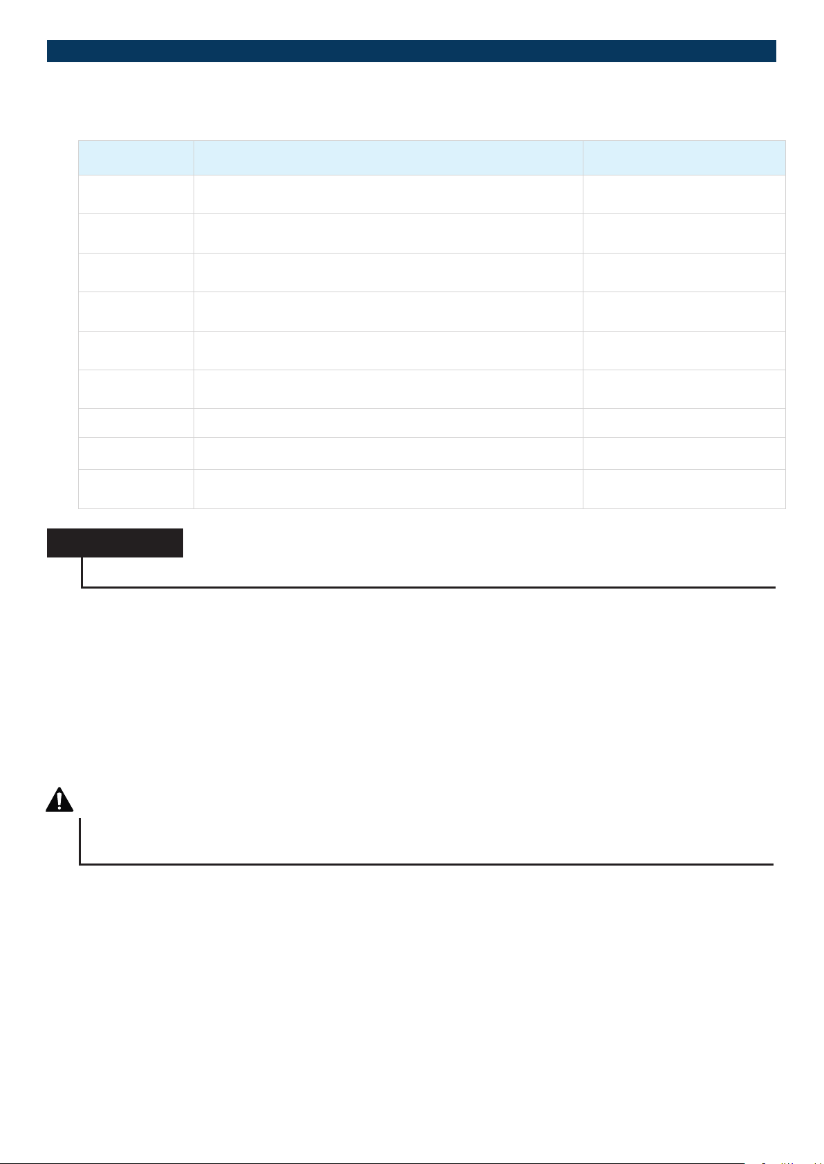
2.10. STATUS DISPLAYS AND ERROR MESSAGES ON THE DISPLAY
MAILFUNCTION CAUSE MEASURE
Overtemperature - temperature above the alarm limit from
parameter A1
Undertemperature - temperature below the alarm limit from
parameter A2
Fault on sensor F1, short circuit
Fault on sensor F1, break
Fault on sensor F2, short circuit
Fault on sensor F2, break
Internal fault, control unit Repair control unit
Fault in parameter memory Check all parameters
Fault in the data memory Repair control unit
NOTICE
The given table does not apply to custom control units (see programming instruction).
Check sensor F1
return air
Check sensor F1
return air
Check sensor F2
defrost/evaporator sensor
Check sensor F2
defrost/evaporator sensor
3. OPERATION - CARE
This chapter explains the proper start-up as well as cleaning and care of the units.
3.1. INITIAL START-UP
Before the initial start-up, a waiting period of at least two hours must be kept after the installation. This rest period ensures that any
oil that is located in the compressor capsule, which could have become displaced during transport, can run back to the compres
sor (applies to self-contained cooling appliances).
-
DANGER
Danger from electrical voltage on live components
Before start-up, check the cable connections and power supply once again for correctness and contact.
The unit is pre-cleaned before delivery. Nevertheless, we still recommend that you clean the unit thoroughly with a suitable disinfectant
(see Chapter 3.4.2) in order to remove any dirtying.
Subject to technical modications | Valid from August 201924
Page 25
3.2. SWITCHING THE UNIT ON (BUTTON ASSIGNMENT)
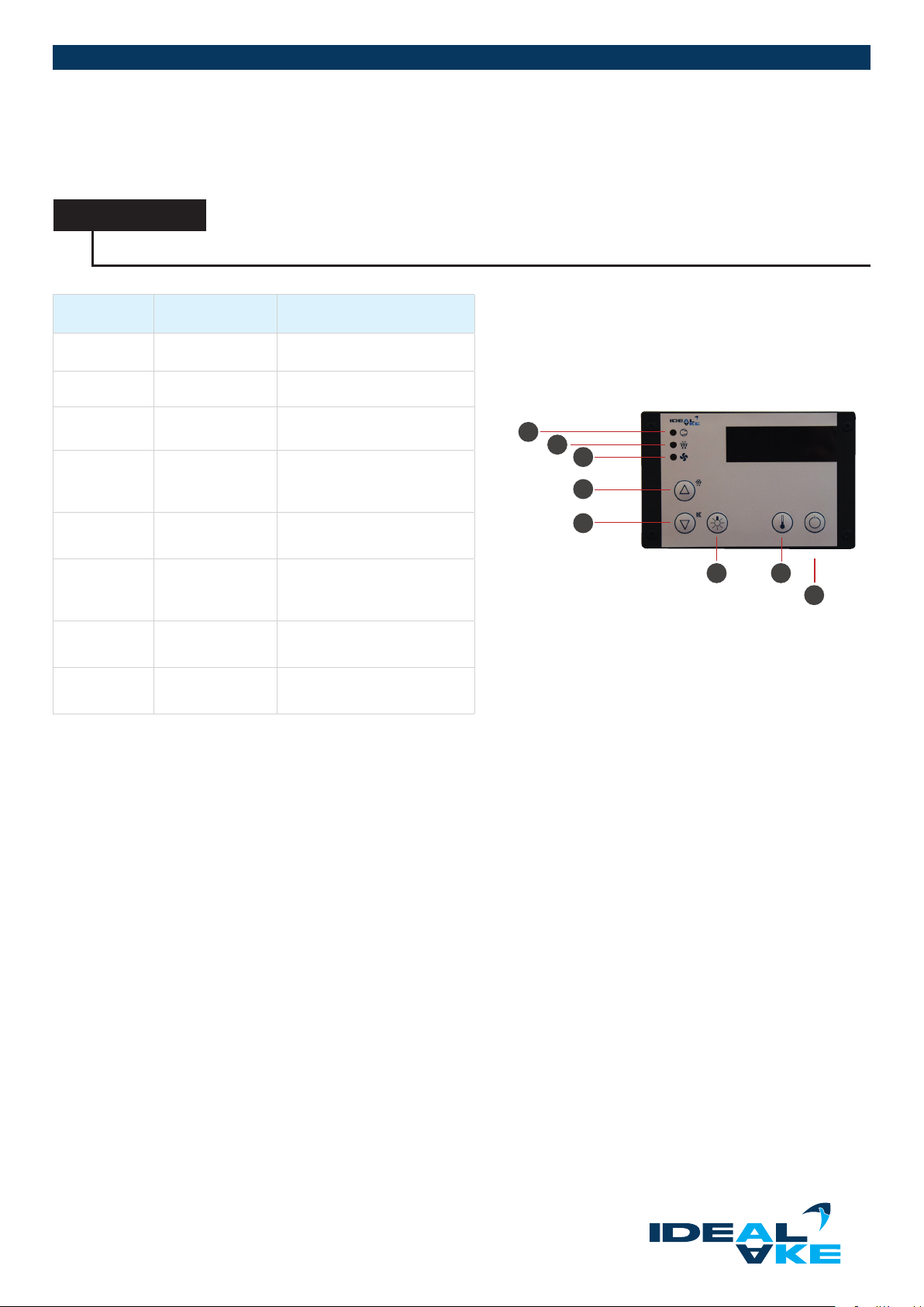
The button assignments and their functions are explained in the following table. The digital display of the cooling controller is above the buttons. The average temperature and any error messages (see Chapter 2.10) are shown here.
NOTICE
Before stocking the unit with refrigerated product, wait until the desired temperature is reached.
BUTTON DESCRIPTION FUNCTION
1 Cooling Display red = active
2 Defrosting Display red = active
3 Fan
4 UP
5 DOWN
6 LIGHT
7 SET
8 STAND BY
Evaporator fan,
display red = active
Increase value
Start defrosting (hold for
appr. 3 seconds)
Decrease value,
Acknowledge alarm
Button not assigned;
optional for switching the
lighting on/o.
Display target value and
parameter setting
Unit on/o (stand-by)
(hold for appr. 4 seconds)
1
2
3
4
5
6 7
8
Subject to technical modications | Valid from August 2019 2 5
Page 26
REFRIGERATED DISPLAY CASES
3.2.1. UNITS WITH REFRIGERATED COUNTERS
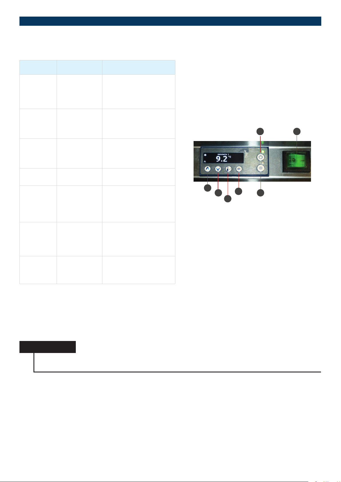
BUTTON DESCRIPTION FUNCTION
Increase value,
1 UP
2 AB
3 OK
4 MENU/EXIT
5 LIGHT
select menu item
Model with night roller blind:
Raise roller blind
Decrease value,
Select menu option
Model with night roller blind:
Lower roller blind
Save settings/changes/
values, Acknowledge alarm,
Target value setting:
hold for appr. 2 seconds
Unit settings,
close menu option
Light on = active,
light o = inactive,
(dimmable depending on
model: hold for appr. 4
seconds)
1
2 5
3
6 7
4
Unit on/o (stand-by)
6 STAND BY
7 ON/OFF
(hold for appr. 4 seconds),
unit on = green,
unit o (stand-by) = red
Main switch:
I = On,
0 = O
NOTICENOTICENOTICE
3.2.2. TEMPERATURE SETTING
The interior temperature is regulated via the display of the electronic temperature controller. It is located on the control box. The
factory set target value can be shown by pressing the SET button. The temperature that you desire can be set by holding the SET
button and simultaneously pressing the UP button for a higher temperature or alternatively the DOWN button for a lower temperature. You can nd the exact button assignment in Chapter 3.2.
NOTICE
The factory set target value can be shown by pressing the SET button. This is set according to the unit.
An adjustment is only permissible by an authorised specialist.
After changing the temperature settings, it takes some time for the desired temperature to be reached in the unit and stabilise (check
the set temperature with a suitable test thermometer). The temperature should be set by the supplier or specialist dealer during the
installation. Observe the ambient conditions when choosing the inside temperature. A large temperature dierence between the
inside and outside temperature combined with high air humidity can lead to heavy ice formation and condensate. This reduces the
refrigeration capacity and prevents the automatic defrosting from working properly.
Subject to technical modications | Valid from August 201926
Page 27
3.2.3. SENSOR CALIBRATION
For a new installation and start-up of a unit, a sensor calibration is only possible after the target value temperature has been reached.
This will take some time.
NOTICE
The cooling controller is completely set and ready for operation. After completion of the installation, check parameter
H12 (calibration of return air sensor). The cooling controller must be carried out by an authorised expert according to the
enclosed programming guide.
3.3. STOCKING THE UNIT AND ADJUSTING THE HEIGHT
OF THE SHELF
Conguration
Stock the unit with pre-cooled product via the sliding or alternatively hinged doors from the operator side, and on the customer side
for units with the back wall closed. The products can be placed on glass shelves and on the base deck.
NOTICE
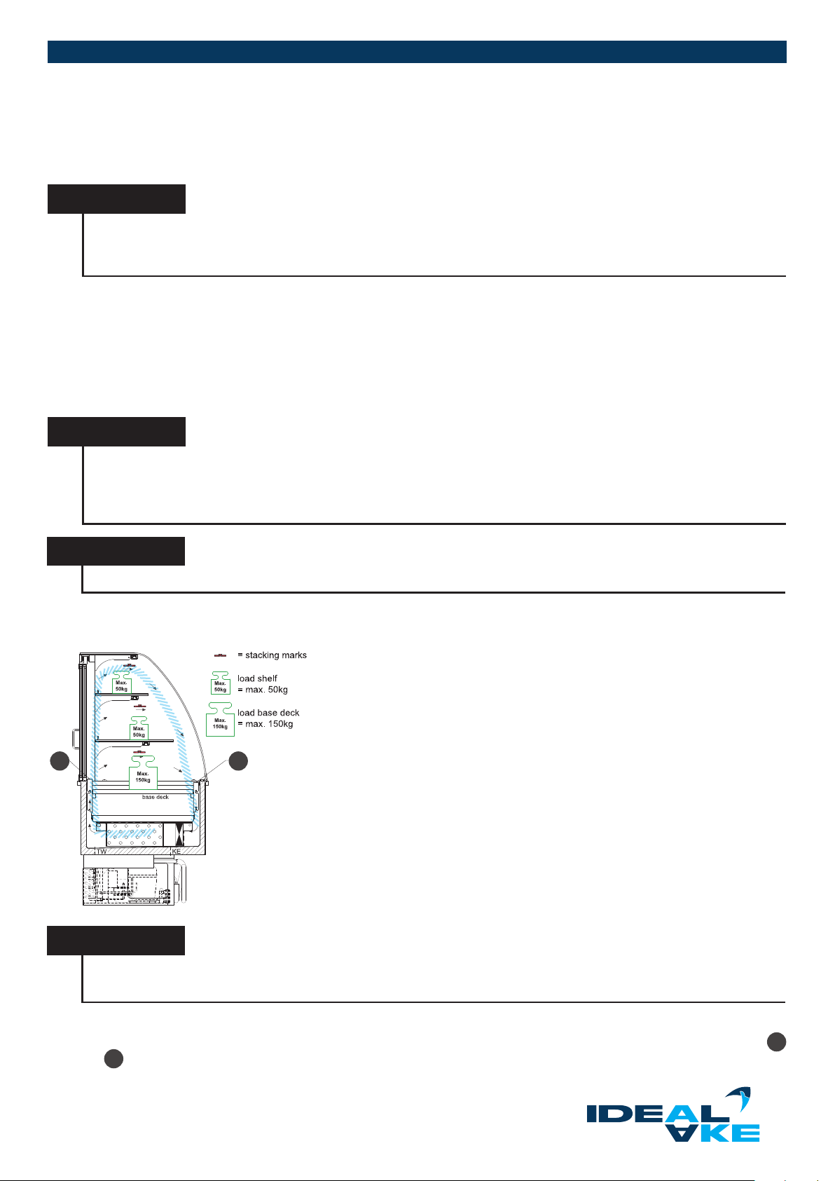
Observe the maximum carrying capacity of the shelves.
Maximum load:
• Bottom, a total of 150 kg.
Make sure that you do not store any kegs and bottles on the glass shelves.
NOTICE
Ceramic plates can cause scratches on powder-coated shelves.
R Correct stocking
12
Cold air curtain of the unit not impeded/interrupted by products.
Optimal cooling and presentation of the products.
NOTICE
Flawless functioning can only be guaranteed if the supply and return air openings are kept free and the cold air curtain
is not blocked.
For units with convection cooling, the presented products are cooled by a directional air curtain of cooled air. A minimum distance of
40 mm must be kept (see drawn-in stacking marks) from the lighting and air exhaust openings. The ventilation slits on the front
and back 2 side of the unit must not be covered under any circumstances.
Subject to technical modications | Valid from August 2019 2 7
1
Page 28
REFRIGERATED DISPLAY CASES
WARNING
Danger of crushing and from falling objects when moving the glass shelves
Always use both hands to remove and replace the glass parts. Be very careful when handling glass.n.
WARNING
Danger of crushing when handling/aligning/positioning heavy individual components
When handling heavy objects, be aware of possible crushing dangers, also for other persons. If possible, use both hands
when you handle heavy objects. Get another person to help you if necessary. When handling/aligning/positioning heavy
individual components, wear protective gloves and safety shoes.
Height adjustment
The units are delivered with adjustable height shelves. Due to the deep refrigerated well, there are many possibilities to present
products (see Chapter 2.1). GN trays with a maximum depth of 150 mm can be used. Models of the BAK design are delivered with
at shelves without height adjustment (Backnorm baking sheets with 600 x 400 mm).
3.3.1. STOCKING THE CAKE DRAWER
The units of models BAK L and BAK KSL as well as GREEN L and GREEN KSL are very well suited for the presentation of large
cakes or similar products due to their easy stocking with the cake drawer. All the content found in Chapter 2.3 is also applicable
here and must be followed.
NOTICE
It is important to keep the cake drawer closed when it is not in use. If the cake drawer is not closed completely, then it
is not possible to keep a constant interior temperature.
3.3.2. STOCKING THE REFRIGERATED COUNTER
NOTICE
There is a user’s manual included with the refrigerated counter with detailed information on handling it. The instructions contained in it must be followed.
The interior is designed for the storage of beverages as well as packaged and unpackaged food of all types. Food that is acidic
(such as salads, vinegar, sh and seafood) must be kept vacuum packed or in tightly sealed containers. This does not apply to
CNS (chromium nickel steel).!
ATTENTION
Danger of spoiled food
Unpackaged food can be destroyed by aggressive vapours from the evaporator. This does not apply to
CNS (chromium nickel steel evaporators)!
Pay particular care so that the air openings near to the evaporator are not covered with product. This also applies to the use of GN
trays. Do not overll them. The displayed temperature of the unit does not show the temperature of the products that has just been
put in. Insuciently pre-cooled product requires time before it reaches this temperature. Observe the temperature of the stored
beverages when choosing the inside temperature. Temperatures that are too cold can freeze beverages, which would cause the
glass bottles to burst.
Subject to technical modications | Valid from August 201928
Page 29
3.3.3. HEIGHT ADJUSTMENT OF INTERMEDIATE SHELVES
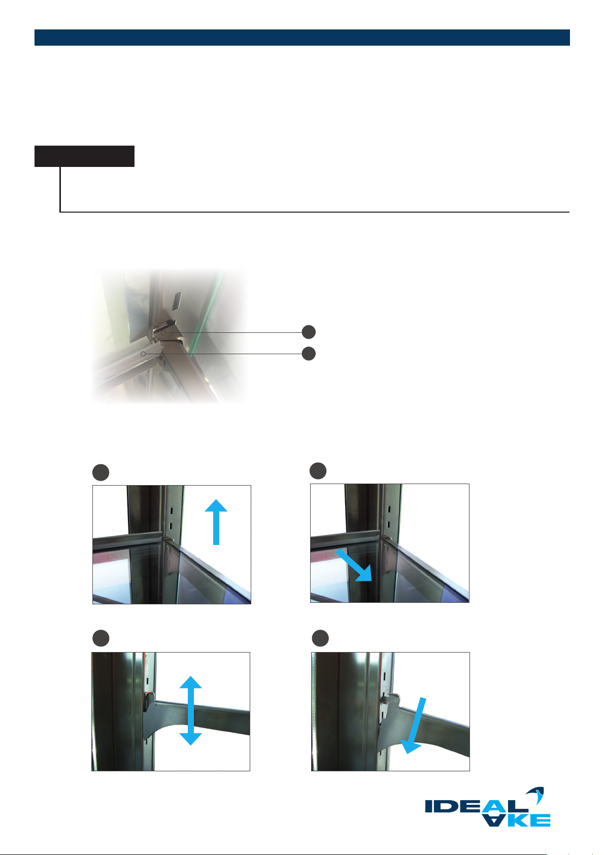
The height and incline of the intermediate shelves can be adjusted in order to adapt the unit to your requirements. The
The intermediate shelves can be moved by one level (± 25 mm) from the middle position.
Removal of glass shelves
NOTICE
All glass shelves can be lifted out for easier cleaning. At least two persons are required for this, depending on the size
of the unit. The safety tabs must be unhooked to do this. Make sure that these safety tabs are put back when the glass
is reinserted.
Before you can adjust the supports, remove the glass shelves (see Chapter 2.1). To do this, lift the glass shelf on the front edge
until the safety tab releases the glass shelf and it can be pulled forwards and out. . Make sure that the product stopper on the operator side faces upwards.
1
2
Moving the shelf supports
The shelf supports are hooked into the recesses with two tabs. The top has two indentations to adjust the incline of the shelf support
(see Chapter 2.1). Step-by-step procedures:
Lift support Pull the support out forwads
1
Hook it in at the desired height Select the inclined/straight position
3 4
2
Subject to technical modications | Valid from August 2019 29
Page 30
REFRIGERATED DISPLAY CASES
3.4. CLEANING AND CARE
To ensure optimum presentation of the products, daily cleaning of the inside and outside must be carried out
in accordance with the hygiene regulations.
DANGER
Danger from electrical voltage on live components
The power supply must be disconnected before all cleaning and service work. To do this, unplug the cooling appliance or
disconnect all poles from the power mains.
WARNING
Danger of being hit by the cooling appliance during installation, cleaning and maintenance work
Be aware of possible dangers of being hit by the unit.
Always turn the machine on before any cleaning work. We recommend performing the daily cleaning at the end of the workday.
The unit can remain switched o overnight or outside of business hours if there are no longer any products in the unit.
3.4.1. CLEANING INTERVALS
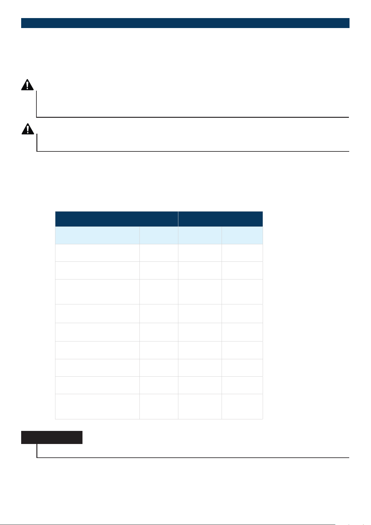
Folgende Sicht- und Funktionsprfungen werden zusätzlich zur Reinigung empfohlen:
ACTIVITY INTERVAL
VISUAL AND FUNCTIONAL
CHECK
Well including drain
(Siphon)
Condensate collecting basin
Hot gas evaporation
Pneumatic springs
(Model dependent)
(glass cover and evaporator)
Condenser
(dirtying, damage)
Cake drawer
(model-dependent)
Refrigerated base
(model-dependent)
Night roller blind, LED
(Model dependent)
All glass (incl. windows and
hinged doors)
Mechanical damage on
all components shown
in Chapter 2.1
DAILY WEEKLY MONTHLY
x
x
x
x
x
x
x
x
x
HINWEIS
The unit must be cleaned daily.
Subject to technical modications | Valid from August 201930
Page 31
NOTICE
All glass shelves can be lifted out for easier cleaning. At least two persons are required for this, depending on the size
of the unit. The safety tabs must be unhooked to do this. Make sure that these safety tabs are put back when the glass
is reinserted.
After cleaning, all parts must be rinsed with clear water and then dried so that no residue remains.
To keep the stainless steel parts of the unit in perfect condition, the following points are essential:
• Always keep stainless steel surfaces clean.
• Ensure adequate air circulation on the surfaces.
• Never touch components of the unit with rusty material.
NOTICE
In addition, persons who perform cleaning work must comply with the measures specied for the respective cleaning
agent (e.g.: Wear gloves when cleaning; wear spray protection and so on).
3.4.2. CLEANING AGENTS
NOTICE
Only the cleaning agents given in this chapter are permissible for cleaning the unit. Do not use any cleaning agents
that contain chlorine.
COMPONENTS/
MATERIALS
Surfaces that come into
contact with product
Glass surfaces Glass cleaner
Stainless steel surfaces Stainless steel cleaner
Base decks and
GN containers
Powder-coated surfaces
Acrylic glass (aps)
CLEANING AGENTS COMMENT
Luke warm
soapy water
Washing up liquid and
brush
Soft cloth, lukewarm
soapy water
Soft cloth, lukewarm
soapy water
Rinse with clear water
The glass panes can be lifted up to make it easier to clean
the panes and areas underneath
Make sure that the stainless steel cleaner that you use is
food-safe.
Base decks and GN containers are easy to remove
(see Chapter 2.1).
Only use brushes with plastic or natural bristles.
Do not use any,
• abrasive or rough cleaning utensils
• glass cleaners
• solvents
Do not use any,
• abrasive or rough cleaning utensils
• glass cleaners
• solvents
Subject to technical modications | Valid from August 2019 31
Page 32
REFRIGERATED DISPLAY CASES
3.4.3. CLEANING THE EVAPORATOR
DANGER
Danger from electrical voltage on live components
The power supply must be disconnected before all cleaning and service work. To do this, unplug the cooling appliance or
disconnect all poles from the power mains.
WARNING
Danger of crushing when handling the evaporator box
When lifting and reinserting the evaporator box, use the metal rod intended for that purpose. When lifting the evaporator
box, make sure that it is lifted far enough until the locking tabs snap into place automatically.
Hold the evaporator box on the metal rod rmly or alternatively in position before unlocking.
WARNING
Danger from leaking refrigerant from a damaged evaporator
Don’t use any sharp objects for cleaning the evaporator ns. The evaporator ns may only be cleaned by products
specied by AKE
NOTICE
When cleaning the unit, wear the respective protective equipment stipulated by the manufacturer of the cleaning
agent being used (see Chapter 3.4.2).
NOTICE
Before cleaning the unit with water, please check that the water can run o. If the unit is not connected directly to the
sewer system onsite, then a suitably sized container must be put under the drain.
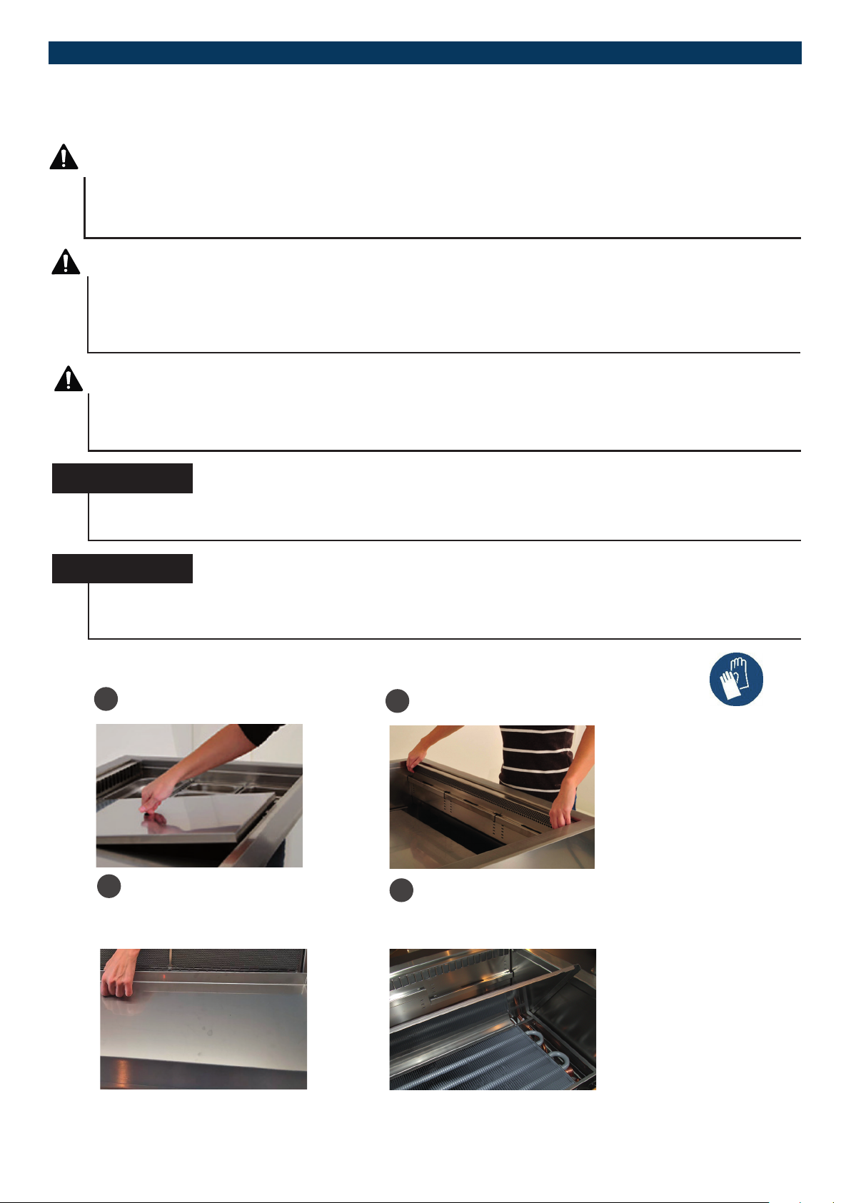
For cleaning the evaporator, proceed as follows:
Remove the base decks or
1
alternatively GN trays
Remove the inserted tray up and
3
out of the unit. Use the round
forms on the inserted tray for this.
Remove the air bae up and out of
2
the unit.
Hochklappen der Verdampfe r-
4
abdeckung. Splen des ge samten
Verdampferkastens sowie der
Lamellen des Verdampfers.
Subject to technical modications | Valid from August 201932
Page 33
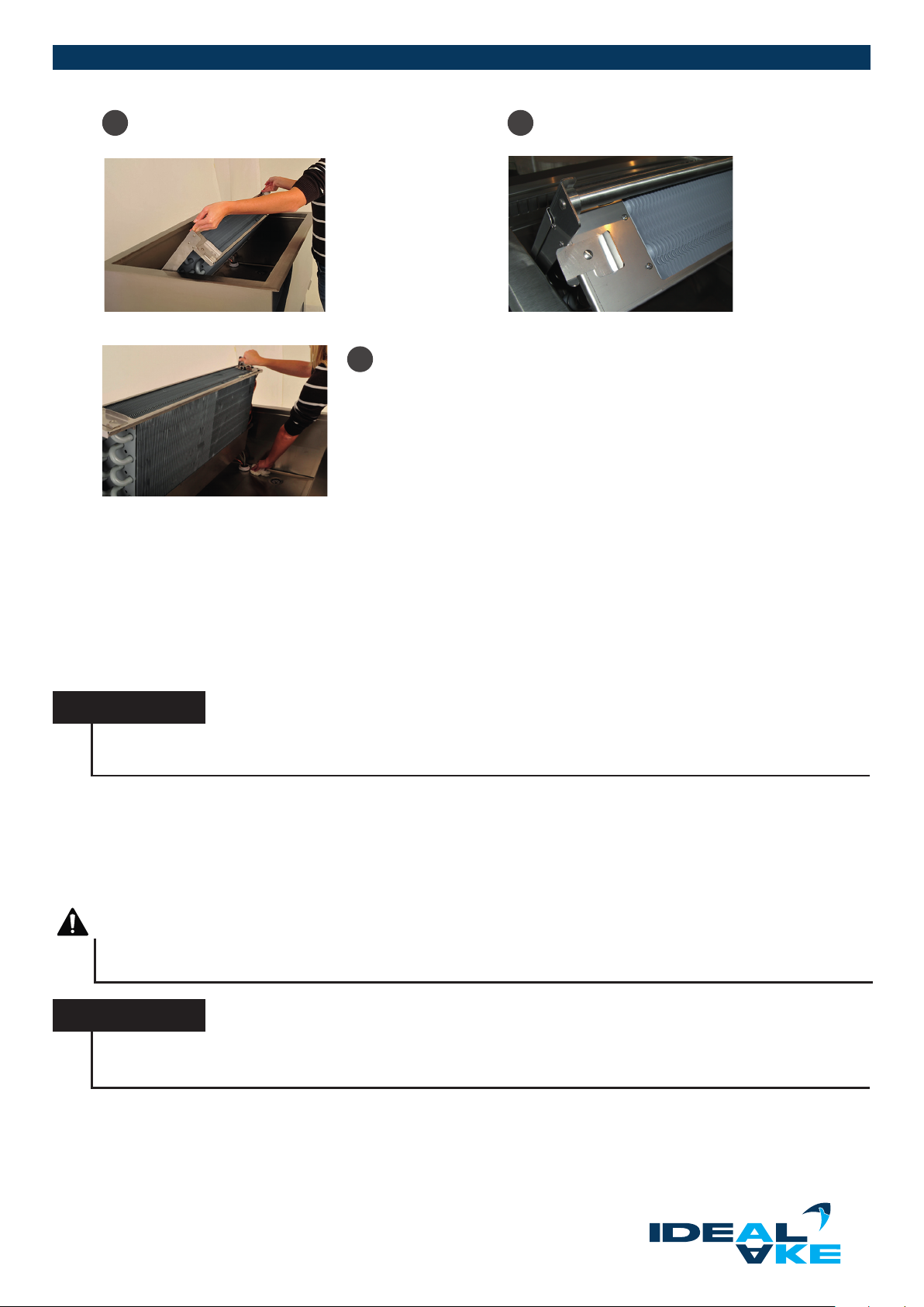
Fold up the evaporator box until
5
the locking tab engages laterally.
Clean the entire interior. First of all remove the
7
coarse dirt so that the drain does not become
clogged. The evaporator and the inside of the
well have to be cleaned with lukewarm soapy
water. Always wipe the interior dry after cleaning.
The evaporator is xed.
6
Nafter completion of the cleaning, proceed in reverse order as follows:
1. Lift up the evaporator box slightly.
2. Swing the side locking device to the inside.
3. Lower the evaporator box (don’t let it fall).
4. Close the evaporator cover..
5. Insert the entire interior correctly.
6. Position the side air bae with the support strips.
7. Put the base decks or alternatively GN containers back.
NOTICE
The outside and underside of the refrigerated well must not be cleaned with a water hose or washing brush. Running
water must be prevented in this area in all cases.
All surfaces can be cleaned with cleaning agents (see Chapter 3.4.2) and water.
3.4.4. CLEANING THE GLASS
The front windows can be tilted forwards for easier cleaning, and pushed in for models with the Easy-Change-System. The glass
covers can be moved upwards making it easier to clean the inside (see Chapter 2.1).
WARNING
Danger from falling objects
Hang on to the glass rmly when cleaning and never let the front glass fall.
NOTICE
For units as of 2/1, two people must be used to manipulate and clean the glass. Do not underestimate the weight of
the glass. This also applies to screwed-on glass enclosures or models with a safety cord
Subject to technical modications | Valid from August 2019 33
Page 34
REFRIGERATED DISPLAY CASES
Models with a safety cord are held in the end position by a safety cord.. However, the glass must still be supported manually when
open to protect the safety cord! The safety cord must be hooked in during cleaning! This also applies to models that are only
equipped with a tilting structure. Use a glass cleaner for cleaning (see Chapter 3.4.2)
NOTICE
All glass shelves can be lifted out for easier cleaning. At least two persons are required for this, depending on the size
of the unit. The safety tabs must be unhooked to do this. Make sure that these safety tabs are put back when the glass
is reinserted.
Hinged and sliding doors
WARNING
Danger of crushing/cutting when moving the sliding or hinged doors
Use the handles designated for that purpose when opening and closing the sliding doors. When closing the sliding doors, do
not reach between the side sections of the sliding door and the unit. Do not reach into the area between the bottom side of
the angle trim and the top edge of the sliding door. Make sure that the angle trim is attached and screwed together properly.
The same thing applies to hinged doors. Be very careful when handling glass.
NOTICE
Only the cleaning agents mentioned in Chapter 3.4.2 are permissible for cleaning the hinged and sliding doors.
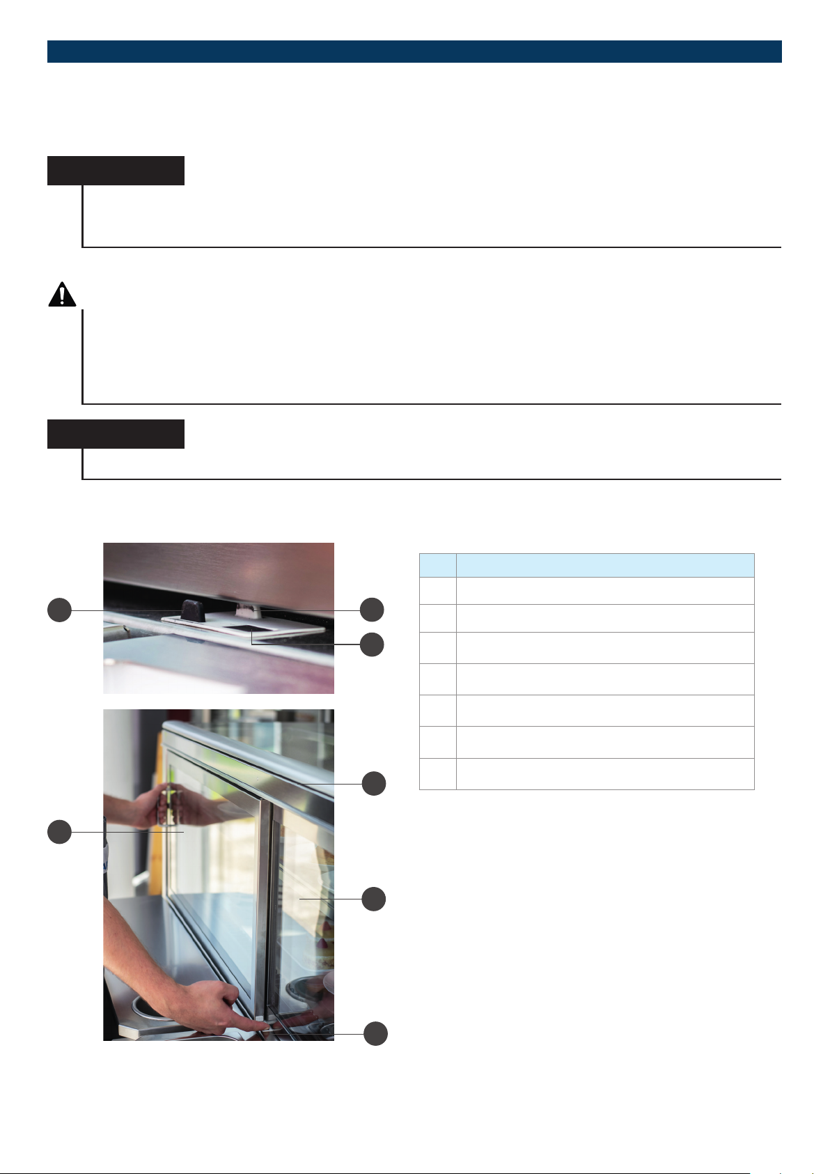
Sliding doors can be taken out of the unit for cleaning by the locking mechanism (see Chapter 2.1). After cleaning, make sure that
all doors are put back again and are completely closed.
No. Name
1 Left door guide
1
2
2 Right door guide
3
5
3 Left door locking lever
4 Left door
5 Running track (not visible)
6 Right door
7 Guide rail
4
6
7
Subject to technical modications | Valid from August 201934
Page 35
WARNING
Danger of crushing/cutting when moving the glass cover or front glass
Wien lifting the glass cover, use the small handle strip designated for that purpose. At least two persons are needed to
open the glass cover or front glass. Close the glass cover and front glass carefully, and watch out for dangers of being
crushed on the glass cover and front glass. Be very careful when handling glass.
NOTICE
For units as of 4/1, 2 people must be used to manipulate and clean the sliding doors. Do not underestimate the weight
of the sliding doors. This also applies to the hinged doors.
NOTICE
Be very careful when handling glass.
1. Hold the door handle rmly with your left hand. Pull the lever of the lock all the way up with your right hand.
2. Leave your left hand on the door handle and clasp the door frame with your right hand. Tip the door towards the operator.
3. Put the door in the position where the recesses are located on the running rail for the rollers. To remove the door from the
guide rail, lift it up slightly and push it to the back.
4. Tip the door up at the front and lift it out of the unit.
5. Store the door on a clean and soft underlay. Make sure that the grip is on the top side.
6. Hold the door handle rmly with your right hand. Clasp the door frame with your right hand. Tip the door towards the operator.
7. Put the door in the position where the recesses are located on the running rail for the rollers. To remove the door from the
guide rail, lift it up slightly and push it to the back. Tip the door up at the front and lift it out of the unit.
9. Store the door on a clean and soft underlay. Make sure that the grip is on the top side.
10. Clean the doors and overlapping zone. Check the rollers on the sliding doors to make sure they move freely.
They must be free of any dirtying.
NOTICE
Zur Reinigung der Schiebetren sind nur die im Kapitel 3.4.2 genannten Reinigungsmittel zulässig.
11. Install the right window once again. To do this, repeat steps 8 to 6 in reverse order. Make sure that the right window is hooked
into the white lock. Put the right window in the far right position.
12. Install the left window once again. To do this, repeat steps 4 to 1 in reverse order. Make sure that the left window is hooked
into the black lock. Put the left window in the far left position.
NOTICE
After cleaning, make sure that all doors are put back again and are completely closed. Check to make sure the sliding
doors move freely.
NOTICE
For units as of 2/1, two people must be used to manipulate and clean the sliding doors. Do not underestimate the weight
of the sliding doors. This also applies to the hinged doors.
Subject to technical modications | Valid from August 2019 3 5
Page 36
REFRIGERATED DISPLAY CASES
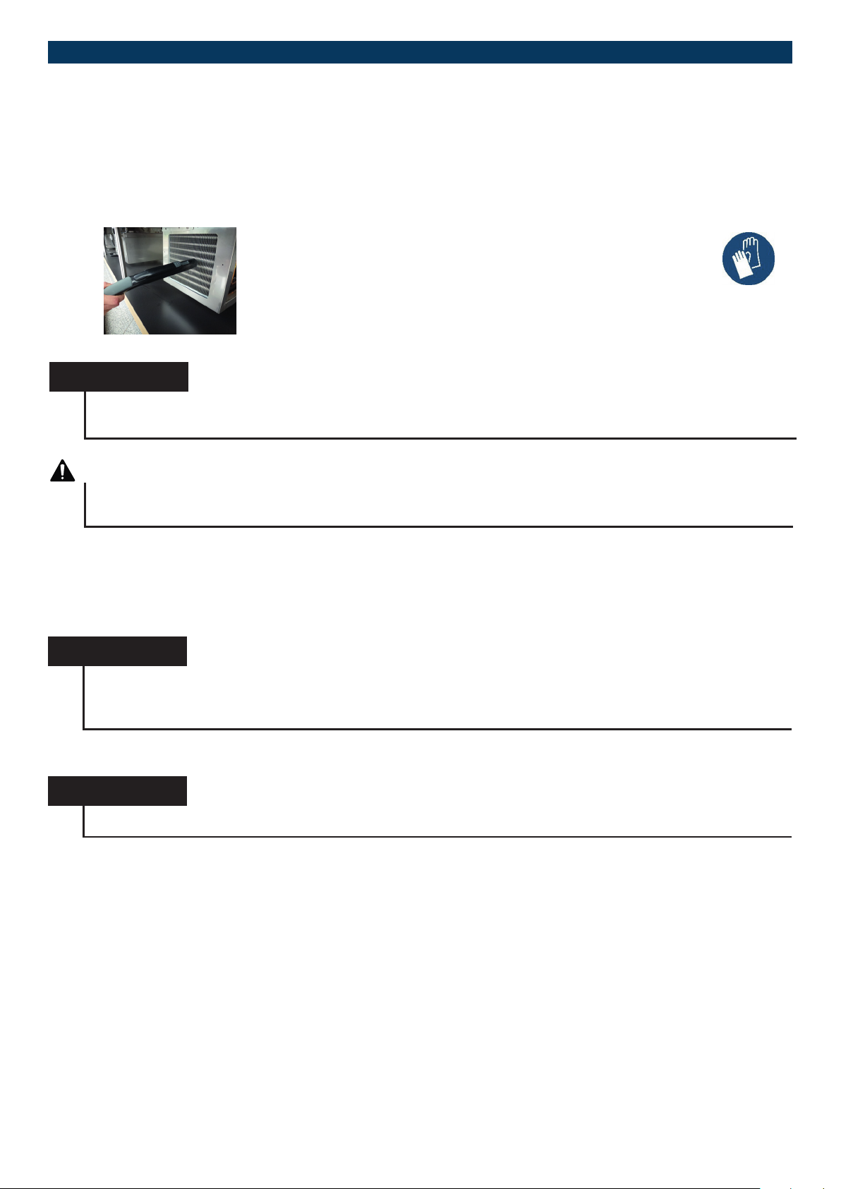
3.4.5. CLEANING OF THE CONDENSER (CONDENSER)
Bei steckerfertigen Geräten muss der Kondensator wöchentlich gereinigt werden und laut Kapitel 3.4 täglich eine Sichtkontrolle erfolgen. Ein verschmutzter Kondensator fhrt zu verringerter Kälteleistung, Überhitzung des Kälteaggregates bis hin zur Schädigung
des Kompressors.
Wear protective gloves for cleaning.
Guide to cleaning the condenser
1. Remove the ventilation grille or condenser protector.
2. Remove dirt by vacuuming it o with a vacuum cleaner.
Make sure that the ns are not bent.
3. Install the air grill
NOTICE
The ingoing and outgoing air openings of the condenser must not be closed or blocked by objects, otherwise the coo-
ling capacity will be hampered or in worst case, the compressor destroyed.
ATTENTION
Danger of cuts
The ns of the condenser are very thin and sharp. Avoid direct contact with the ns in order to prevent injuries.
3.4.6. CLEANING THE NIGHT ROLLER BLIND
The night roller blind (model-dependent) must be cleaned weekly in accordance with Chapter 3.4.1. Exclusively the cleaning
agents mentioned in Chapter 3.4.2 are permissible for cleaning the unit. Depending on the model, it is possible to have a mechanical or electric night roller blind (see Chapter 2.1). For operation with units with a refrigerated counter, see Chapter 3.2.1.
NOTICE
Technical changes to the unit may only be carried out by specialists. This applies in particular to work on the refrigeration
system, electrical installation and mechanics.
Any change must be authorised by the manufacturer.
3.4.7. CLEANING THE REFRIGERATED COUNTER
NOTICE
For cleaning the refrigerated counter, follow the included user’s manual.
The refrigerated counter (model-dependent) must be cleaned weekly. Please observe the instruction in Chapters 3.4
and 3.4.1. Only the cleaning agents mentioned in Chapter 3.4.2 are permissible for cleaning the unit.
Subject to technical modications | Valid from August 201936
Page 37
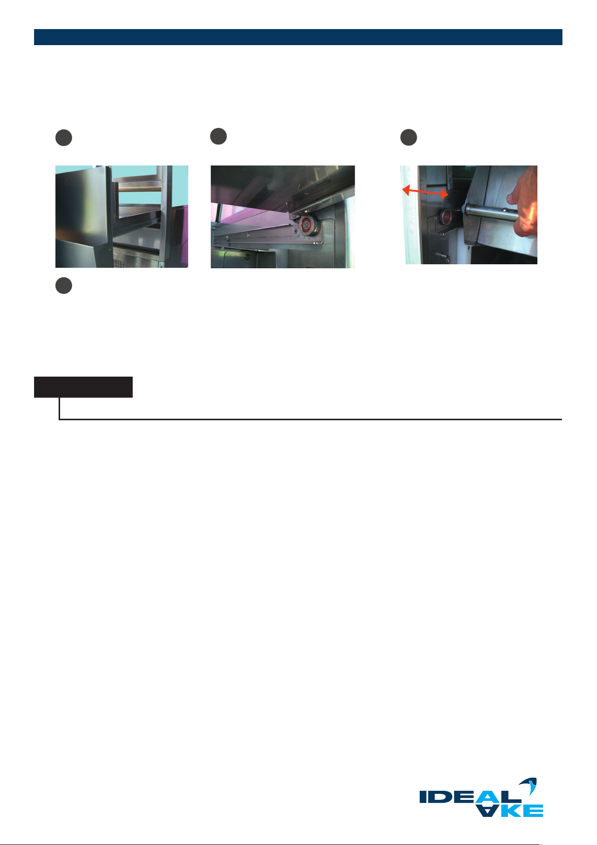
3.4.8. CLEANING THE CAKE DRAWER
To clean the refrigerated counter, remove the cake drawer from the unit. Proceed as follows:
Pull the drawer out as far
1
as it goes (see gure 1).
4
Clean the bottom tray underneath the evaporator
Lift the drawer around 5 cm so
2
that it can be unhooked
(see gure 2).
After cleaning:
1. Lift up the evaporator. Remove the locking pins on both sides (see gure 3).
2. Lift up the drawer and then hook it in again (see gure 2).
3. Push the drawer back in and close it.
NOTICE
Only the cleaning agents mentioned in Chapter 3.4.2 are permissible for cleaning the unit.
Lift up the evaporator. Secure
3
on both sides by the locking
pins (see gure 3)
Subject to technical modications | Valid from August 2019 3 7
Page 38
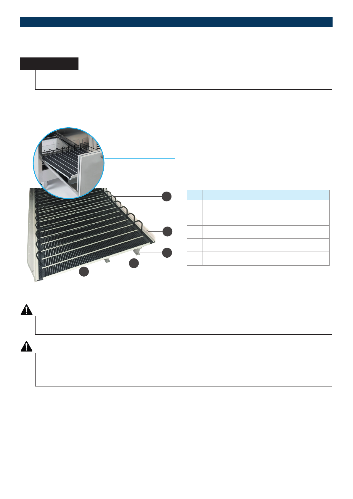
REFRIGERATED DISPLAY CASES
3.4.9. CLEANING THE BOTTLE SLIDER
NOTICE
Only the cleaning agents mentioned in chapter 3.4.2 are permitted for cleaning the device. After cleaning, all parts
must be rinsed with clear water and then dried to avoid residues.
For devices with charger (depending on model), proceed as described in chapter 3.4.8 to completely remove the ex roller system.
Reinsert the Flexroller (depending on model with elevation prole) together with the acrylic front glass and PVC rear pane.
Fit the dividers according to the product dimensions.
Bottle slider with drawer
1
2
3
4
5
No. Name
1 Wire divider
2 PVC rear window (operating side)
3 Aluminum elevation prole (depending on model)
4 Flex roller
5 Acrylic front panel (customer side)
WARNING
Danger of shock to equipment during assembly, cleaning and maintenance work
Pay attention to possible shock hazards on the device.
WARNING
Danger of crushing and falling objects when handling/adjusting/positioning individual components
When handling objects, watch out for possible crushing hazards, even for third parties. Use if possible, both hands
when handling objects. Wear protective gloves and safety shoes when handling/adjusting/positioning heavy individual
components.
Subject to technical modications | Valid from August 201938
Page 39
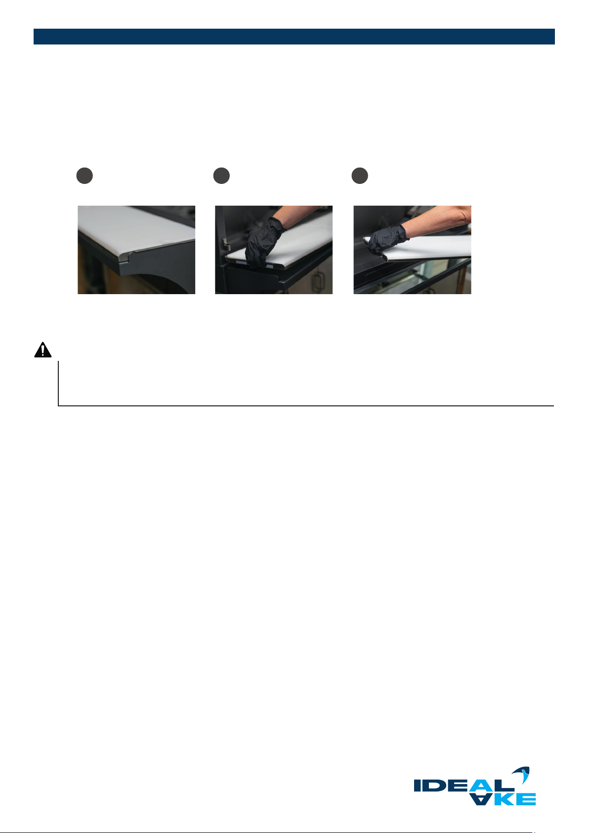
3.4.10. CLEANING THE CUTTING BOARD
The cutting board consists of a removable CNS tray with one or more polyhygiene inserts. The polyhygiene inserts can be removed
from the CNS holder for cleaning.
When the hinged doors are unhooked, the entire cutting board including the CNS tray can be lifted to the side and
then lifted out of the guide.
Cutting board hooked
1 2 3
in, mirror underneath.
Lift the cutting board sup
port out of the anchoring.
-
Remove the cutting board
support.
3.4.11. CHECKING THE GAS DAMPER
DANGER
DANGER from defective gas damper
Check the gas damper of the primary hotplate monthly to make sure it functions properly. Replace it if it is defective.
Observe the service life and maintenance intervals given by the manufacturer.
Subject to technical modications | Valid from August 2019 39
Page 40
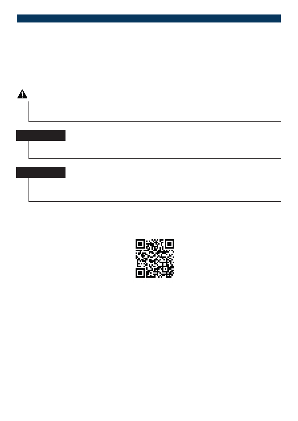
REFRIGERATED DISPLAY CASES
4. SERVICE/MAINTENANCE
4.1. MAINTENANCE INFORMATION
The unit must be checked and maintained for perfect functioning of the unit and optimum product presentation. The units are subjected to individual testing at the factory according to EN 60335-1 Annex 7 (Recommendation: annual follow-up inspection according
to VDE 0701-0702 by the operator).
DANGER
Danger from electrical voltage on live components
The unit must be switched o by the main switch until the maintenance, inspection and repair work is completed. Switching
on unsupervised must be prevented.
Service and maintenance guides can
be found under the following QR
code:
NOTICE
Execution of the maintenance activities by the operating personnel or operator applies exclusively to the activities listed
in Chapter 3.
NOTICE
Technical changes to the unit may only be carried out by authorised specialists. This applies in particular to work on the
refrigeration system, electrical installation and mechanics.
Any change must be authorised by the manufacturer.
Service and maintenance guides can be found under the following QR code:
If you don‘t have a QR code reader, you can nd one in the download area on our homepage, or else please
contact your supplier or specialist dealer.
4.2. PURCHASING SPARE PARTS
To buy spare parts, contact your supplier or specialist dealer. Each unit is equipped with a rating plate (see Chapter 1.7). Give the
specic unit data to your authorised specialist. The information on the type and serial number as well as the date of manufacture
are required for the assignment. Spare parts lists for your unit can be found in the Downloads menu at www.ideal-ake.at
Subject to technical modications | Valid from August 201940
Page 41
5. DECLARATION OF CONFORMITY
EU Declaration of conformity
in accordance with EU guidelines 2006/42/EC and 2014/30/EC
Manufacturer Ausseer Kälte und Edelstahltechnik GmbH
Pichl 66, 8984 Bad Mitterndorf, ÖSTERREICH
Product Refrigerated display cases
Type see Chapter 1.3
Year of construction as of 2019
Compliance of the products given above with Machinery Directive 2006/42/EC and EMC Directive 2014/30/EU is hereby conrmed.
The basic requirements from Machinery Directive 2006/42/EC and the essential requirements from EMC Directive 2014/30/EU and
RoHS 2011/65/EU were complied with. The required technical documents were prepared and archived. The following harmonised
standards for Machinery Directive 2006/42/EU were applied in their currently valid version:
DIN EN 60335-1 (VDE 0700-1) :2012-10;
Safety of electronic devices for home use and similar purposes – Part 1: General requirements
(IEC 60335-1:2010, modied)
DIN EN 60335-2-89 (VDE 0700-89) :2016-11;
Safety of electronic devices for home use and similar purposes - Part 2-89: Special requirements for commercial freezers and refrigerators with an integrated or separate condensing unit or motor compressor (IEC 60335-2-89:2010 + A1:2012, modied)
DIN EN 378-2:2017-03
Refrigerating systems and heat pumps - Safety and environmental requirements - Part 2: Design, construction, testing, marking and
documentation; German version EN378-2:2016
DIN EN ISO 12100:2011-03
Safety of machinery - General principles for design - risk assessment and risk reduction (ISO 12100:2010);
In the event of technical changes to the product given above, which are not agreed on with the manufacturer,
this EU declaration of conformity loses its validity.
Bad Mitterndorf, 2019 Andreas Pilz (CTO)
Subject to technical modications | Valid from August 2019 4 1
Page 42
NOTES
Subject to technical modications | Valid from August 201942
Page 43
Subject to technical modications | Valid from August 2019 4 3
Page 44

www.ideal-ake.at
Subject to technical modications | Valid from August 201944
 Loading...