

AKD HF3 User Guide
Front end receiver modification for DRM: AKD Target Communications receiver. Model HF3.
Summary. The receiver was modified and capable of receiving DRM, but performance was limited by
the phase noise from the 1st Local Oscillator (LO).
With the receiver on test, fed with a signal direct from a DRM modulator, the phase noise from the 1st
LO limited the SNR as reported by the receiver software to 21dB. If the 1st LO was replaced with the
output from a Hewlett Packard frequency synthesiser, the measured SNR improved dramatically to a
maximum of 35 dB (equivalent to the SNR achieved when using the AOR 7030 receiver).
With a good strength off air signal (the 15MHz transmission from Sines) the SNR was 17 to 18dB,
whereas the AOR gave 23 to 24 dB.
Because of this phase noise, even with good signal strength, the receiver could not decode the audio
(but was able to lock to the Fast Access Channel, FAC) for the higher data rate (less robust) DRM
transmissions. For lower data rate transmissions, where an SNR of less than 20dB is adequate, audio
could be decoded. In fact, most transmissions on shortwave are in the mid data rate category
(requiring an SNR of 12-17dB), so this receiver will work in most cases.
Modification Details.
The receiver utilises a fairly standard design, mixing the input signal with a (higher frequency)
synthesized LO to give a first IF of 45.0MHz. This 1st IF has a +/- 3.75kHz wide crystal filter. The 1st IF
is then mixed with a second (crystal) LO to give the second IF of 455kHz. This second IF has
selectable ceramic filters, narrow (+/- 2kHz) for SSB use, and a slightly wider (+/- 3kHz) filter for AM.
The DRM signal is 10kHz wide (on SW, MW in Europe uses 9kHz) so both IF filters are too narrow. In
practice a 1st IF filter of +/- 7.5kHz and 2nd IF filter of +/- 6kHz are about optimum for DRM reception.
1st Steps
The first modification attempt was to replace the first IF filter, and take a feed of the 455 kHz IF from
just prior to the existing AM filter and feed it into an add on board. This consisted of an emitter
follower buffer stage (to avoid loading the existing circuitry) and +/- 7.5kHz ceramic filter LTU455E.
This then fed a 455kHz down converter board to produce the 12kHz IF to feed into a PC soundcard
(the 455-12kHz converter board is the same one that is used in the AOR 7030 receiver or
http://www.aoruk.com/drm.htm)
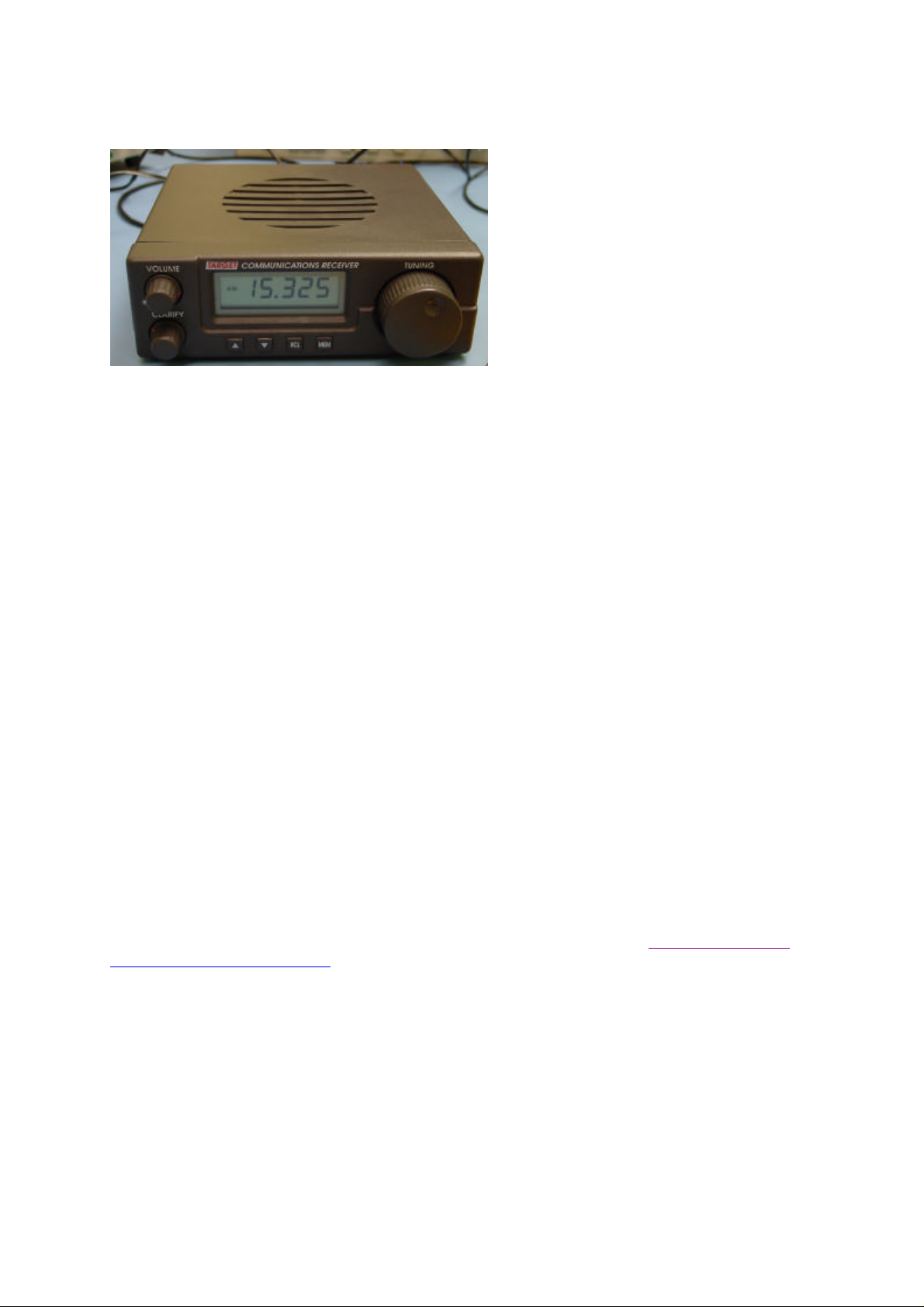
The receiver and software did work at this stage, it was possible to listen to the DRM signal from
Radio Netherlands (broadcast from Bonaire) in the UK, but it only worked for the more robust DRM
modes. It was not possible to decode the signal from Sines in Portugal, even though the signal
strength was much higher than Bonaire. The Deutche Welle (Sines) signal used a much higher data
rate (less robust signal). The AOR 7030 had no problems with either of these signals, and the
software could provide audio from both.
This screen shot of the software was
generator! A better receiver would give a
taken of using the output from the AKD
HF3. It works, but the input was a test
flat top and steep sides.
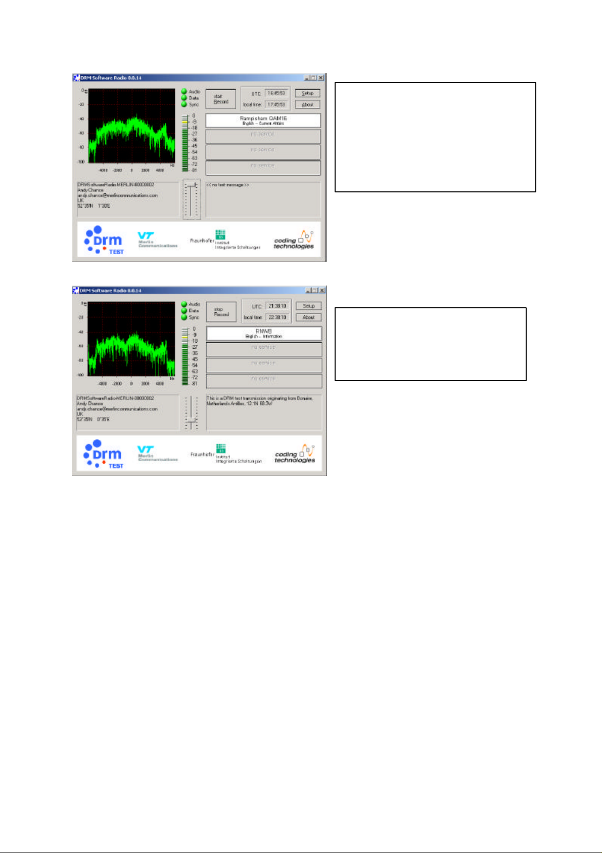
Here a real signal is used, received in
the UK from Bonaire in the Netherland
Antilles. The audio is decoded OK.
2nd Steps
Although the receiver was able to decode robust mode signals at this point, the amplitude response
was very poor. Working through the stages: the first IF filter (which was originally a 2pole filter) I had
replaced by a 4 pole 45 MHz monolithic crystal filter, type 45G15B1. These did not match in well with
the existing circuitry, and were giving an 8dB p/p ripple across the wanted frequency range. Adding
additional buffer stages to provide the specified terminating impedances brought the filter into spec,
with less than 1dB p/p ripple across its passband.
This improved the overall receiver response, however there was still a 10dB notch visible at –1kHz
from centre, and a 20dB notch at +3kHz from centre. These notches turned out to be due to the
existing ceramic filters. The loading they present in circuit varies with frequency, and at frequencies
outside each edge of the filter passband it provides a low impedance path to ground, giving a dip in
the amplitude response.
The SSB filter is permanently in circuit, switching to AM mode is accomplished by putting a short
across the filter (input to output). To remove its effect on the IF response it was necessary to remove
the filter entirely from the board, and put a permanent shorting link across.
(Note: in SSB mode this means the IF bandwidth is now set by the wider AM filter. See the To do
section.)
Removing the effect of the AM filter was achieved by cutting the track leading to the filter, so the
455kHz IF feeds solely into the add-on board. An emitter follower buffer amplifier was added to the
output of this, and the output now fed to both the 12kHz converter board, and back to the receiver at
the input of the AM filter.
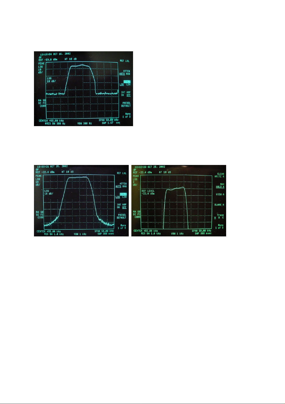
This gave an overall response RF in to 455kHz out at the input of the 12kHz converter board of:
The response is significantly improved, but still shows some ripple and falls off a bit steeply at the
high frequency end.
With a bit of adjustment to the three 455kHz IF coils, the final response below was achieved:
Response 10dB/div Response 2dB/div
Centre 455kHz, 5kHz/div
3rd Steps
With the receiver amplitude response virtually flat across the required +/- 5kHz bandwidth occupied
by the DRM signal, the maximum obtainable SNR (as reported by the receiver software) was still only
20dB, even on the test bench fed directly by a DRM modulator. In comparison the AOR 7030 was
capable of almost 35dB SNR under the same conditions. The problem is the first LO phase noise.
Replacing the internal LO with an external HP (high quality, Expensive!) synthesizer produced a
dramatic improvement in SNR to 35dB.
 Loading...