

Page 1
r-"
AKAI
pyofessiona[
PEQE
PROGRAMMABLE
EQUALIZER
J
To
prevent
fire
or shock
hazard,
do
not
expose this
appliance
to rain
or moisture.
Operator's
Manual
Page 2

{,(
"G
Warning
L"
t
Precautions
Power requirements
Power
requirements
for electrical
equipment
differ
from area
to area.
The operating
voltage of
this machine
is
preset
at the
factory
according
to it's intended
destination.
Howev-
er, some
models
are equipped
with a voltage selector.
If
your
machine
is
so
equipped,
before
connecting,
check
to
see
that
the VOLTAGE SELECTOR
on the
rear
panel
is
set
to the voltage
for
your
area.
If not,
please
set it correctly
before
plugging
in
the
power
cord.
220Y,50H2
for Europe
except
the
UK.
240Y,50H2
for UK
and Australia.
l20Y,60Hz
for
USA
and
Canada.
If the VOLTAGE
SELECTOR
is
not set
for
your
area:
Confirm
that
the
power
cord
is disconnected.
Move
the VOLTAGE
SELECTOR
with a
screwdriver
so
that
the marker is above
the voltage
for
your
area.
What
you
should
know
to
protect
yourself
and the
Akai
PEQ6
rilatch
out!
You might
get
an electric
shock.
o Never
touch the
plug
with
wet hands.
o Always
pull
out
by the
plug
and never
the
cord.
o
Only
let
a
qualified
professional
repair or
reassemble
the equipment.
An
unauthorized
person
might
touch the
internal
parts
and receive a serious
electric
shock.
o Never
allow
a child
to
put
anything,
especially
metal, into
the equipment.
Let's
protect
the
Akai
PEQ6 too.
o
Use
only a
household AC
power
source.
Never use
a DC
power
source.
o If
water is
spilled
on
the equipment,
disconnect
the
power
and call
your
dealer.
o Make sure
that
the
equipment
is
well ventilated
and
away
from direct sunlight.
o To avoid
damage
to the internal
circuits
and the ex-
ternal
surface,
keep away
from
heat
(stoves,
etc.)
o Avoid
using spray
type insecticide
near
the
equip-
ment. It can
damage
the finishand
might
ignite sud-
denly.
o
To avoid damaging
the Íinish,
never use denaturat-
ed alcohol,
paint
thinner or other
similar
chemicals
to
clean
the
equipment.
o
Place the equipment
on
a flat and solid surface.
To enjoy
the Akai
PEQ6
for a long
time,
please
read
this
operator's
manual
thoroughly.
Should
a
problem
persist,
write down
the
model and
serial
numbers and
all
pertinent
data
regarding
warran-
ty
coverage
as
well as a clear description
ofthe existing
trouble. Then, contact
your
nearest
authorized Akai
Service Station,
or
the Service
Department of
Akai
Electric Company,
Tokyo,
Japan.
FOR
CUSTOMERS
IN
THE
UK
IMPORTANT
FOR
YOUR
SAFETY
The flex supplied
with
your
machine
will
have two
wires as
shown
in
the illustration.
T\ryO CORE FLEX
IMPORTANT
The
wires in
this mains
lead
are
coloured
in accor-
dance
with the followine
code:
Blue:
Neutral
Brown:
Live
As
the
colours of
the wires
in the mains lead of
this ap-
paratus
may nol corre-
spond
with
the
coloured
Blue
{Neutrál)
markings
indentifying
the
terminals
in
your
plug, pro-
ceed as follows:
The
wire which
is coloured
blue must
be connected
to the terminal
which
is marked
with the
letter N
or
coloured
black.
The wire which is coloured
brown
must
be
connected
to the terminal which
is marked
with
the letter L or
coloured red.
*
Do
not
connect
any
wire
to the larger
pin
marked E
or
f
when wiring
a
plug.
Ensure
that all terminals
are
sècurely
tightened
and
that no loose strands
of
wire exist.
A
A\:
A
The lightning
flash
with the arrowhead
symbol
superimposed
across a
graphical
representation
of
a
person,
within an
equi-
lateral
triangle, is
intended
to alert the
user to
the
presence
of
uninsulated
"dangerous
voltage"
within
the
product's
enclosure,
that
may be of sufficient
magni-
tude to constitute
a risk of electric shock.
The
exclamation
point
within an
equilater-
al triangle
is intented
to alert
the user to
the
presence
of important operating
and
maintenance
(servicing)
instructions
in
the literature
accompanying
the appliance.
AffiA
CAUTION, TO REDUCE THE RISK OF ELECTRIC SHOCK
DO NOT
REMOVE
COVER
(OR
BACK)
NO
USER.SERVICEABLE PARTS
INSIDE
REFER
SERVICING
TO
OUALIFIED SERVICE
PERSONNEL
Note: This unit
is not equipped
with a voltage
selector
Page 3
tF
CAUTION
To
prevent
electric
shock, do
not use this
pole-
rized AC
power plug
with
an
extension
cord re
ceptacle
or other outlet
inless
the
bledcs cu
lc
fully inserted
to
prevent
blade
exposure.
LITHIUM
BATTERY
This
product
uses
a lithium bettery
for
memory
back-up.
The lithium
battery
should only
be ro'
placed
by
qualified
service
personnel.
Improper
handling
may cause risk
of explcion.
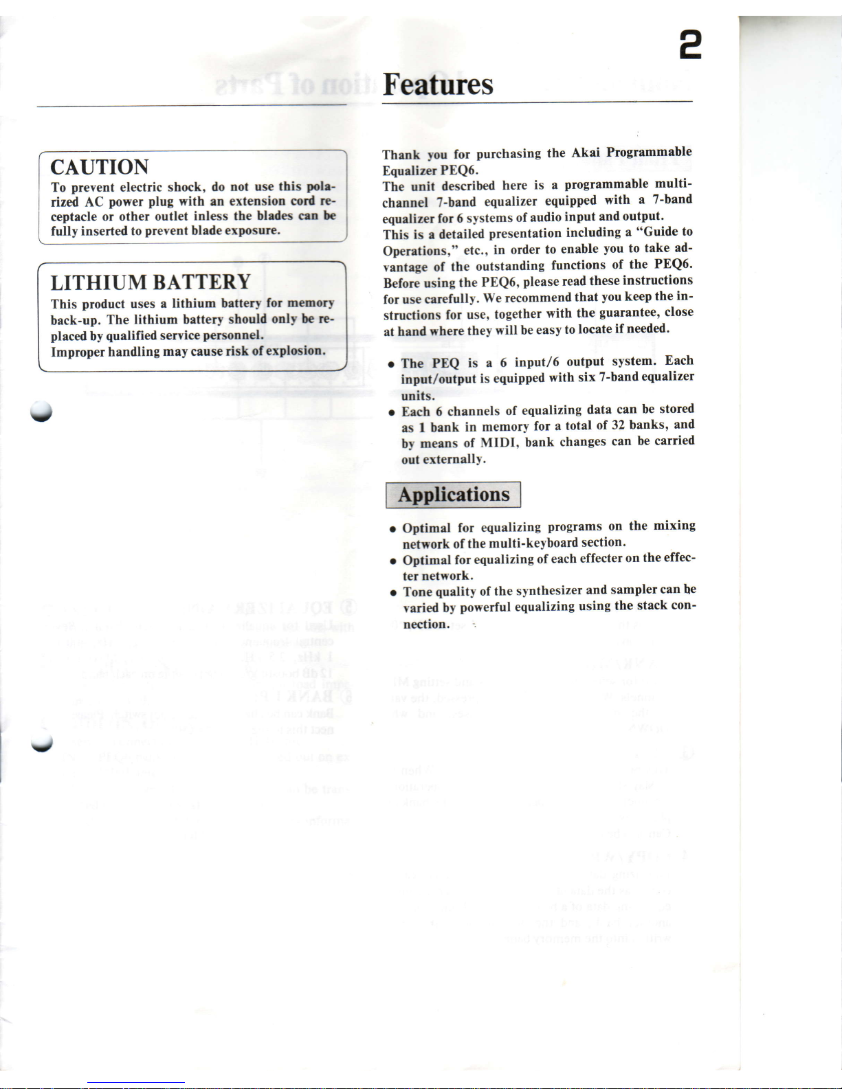
Features
Thank
you
for
purchasing the
Akai
Programmable
Equelizer
PEQ6.
The
unit
described
here
is a
programmable
multi-
channel
?-band
equalizer
equipped
with
a
7-band
equalizer
for 6
systems
of audio
input
and
output'
This
is r detailed
presentation
including a "Guide
to
Operetions,"
etc.,
in order
to
enable
you
to take
ad-
vantege of
the
outstanding
functions
of
the
PEQ6'
Before using
the
PEQ6,
please
read
these
instructions
for use
carefully.
\Ve recommend
that
you
keep
the
in-
struc{ions
for
use,
together
with
the
guarantee,
close
at
hend
where
they
will be
easy
to
locate
if
needed'
o
The
PEQ
is a 6
input/6
output
system.
Each
input/output
is
equipped
with
six
7-band
equalizer
units.
o
Eech
6 channels
of
equalizing
data
can be
stored
es I
bank
in memory
for a
total
of 32 banks'
and
by
meens
of
MIDI,
bank
changes
can
be carried
out externally.
o
Optimal
for equalizing
programs on
the
mixing
network
of
the
multi-keyboard
section.
o
Optimal
for
equalizing
of
each
effecter
on
the
effec-
ter
network.
o Tone
quality
of the
synthesizer
and
sampler
can
be
varied
by
powerful equalizing
using
the
stack
con-
nection.
a
J
Page 4

Nomenclature
and
Operation
of
Parts
O
e
pownn:
When
it is set
to ON,
*00"
This
is
the
Power
switch
is
displayed.
BANK/MIDI:
Used
for selecting
memory
banks
and setting
MIDI
channels.
When
the
UP
button
is
pressed,
the
value
of
the
number
displayed
increases,
and
when
DO\ryN
is
pressed, it decreases.
e
nqull,,tZER
GAIN:
Used
for
èqualizing
data
for each
channel'
Seven
central
frequency
bands:
63
Hz,
160
Hz,
400
Hz,
I kHz.
2.5
kHz.
6.3
klj'z,
16
kHz.
Maximum
of
l2 dB
boosting/cutting
possible on
each
band'
@
ne.Nr
uP:
Bank
can be
changed
using
a foot
switch'
Please
con-
nect
this
to the
Akai
PS-X80.
a
@
lrNn:
This
button
sets
the
equalizing
channel'
When
the
display
shows
"00,"
this
button
is
not
operational'
Channel
settings
are
operational
when
the bank
dis-
play
shows
u0-32."
Can
also
be
used
for
setting
MIDI
channel'
@
copv/wRITE:
Equalizing
data
set
on
a
particular channel
can be
copied
as
the data
of
the
next
channel,
or
the
multi-
equalizing
data
of
a
bank
can be
faithfully
copied
to
another
bank,
and
the
programmed data
can
be
written
into
the
memorY
bank.
Page 5

'Jffi[TIf
''{'rilcttj
',í
Èrrl
't
it$íll'
O
INPUI
(IINE
I.LINE
6):
This
is
the input
terminal.
Be
sure
to use this
with
line
level. Microphone
cannot
be
connected.
O
OUTPUT
(LINE
I-LINE 6):
This is the output
terminal. Optimum
load impe-
dance
is l0 k ohms
or
above.
@
vrnr
(IN,
our,
THRU):
J
Used
for connection
to external MIDI unit.
IN + PEQ6 bank
change
can
be
carried out on ex-
ternal MIDI unit.
OUT + Program
change
information
can
be
trans-
mitted
from PEQ6
to external
MIDI unit.
THRU
+ A through
terminal
for
sending
informa-
tion
received
with MIDI
IN.
Page 6

onnection
lF-
5
C
The PEQ6
input/output
jacks
are
for use
with
standard
phone
jacks.
A microphone
cannot be
connected
be-
cause
the input/output
level
is line
level.
INPUT
(LINE
l-Line
6): Connect
to "output"
of
keyboard, synthesizer,
effecter,
etc.
OUTPUT
(LINE
I-LINE
6): Connect
to
"input"
of
effecter,
mixer,
amp, etc.
MIDI
IN: Connect
to
MIDI OUT
OT
MIDI THRU Of
other
MIDI units.
*
The
MB76 referred
to
in the diagram
is a 7 input/6
output
programmable
mixing bay. Use
if
for
greater
effectiveness.
MIDI
OUT:
Connect
to
MIDI
IN of
other
MIDI units.
MIDI
THRU:
This
is also
connected
to
MIDI
IN of
other
MIDI units.
KEYBOARD
SYNTHESIZER
MIDI/EFFECTOR
M876
KEYBOARD
SYNTHESIZER
EFFECTOR
M876
KEYBOARO
SYNTHESIZER
MIDI/EFFECTOR
M876
EFFECTOR
MIXER
AMP
M876
t,
PEQ6
rearpanel
Page 7

w
Operation
The PEQ6
displays
"00"
when
the
power
b g to ON.
This
is the mode
of operation
as a 6 in/ó
oui'bormel
multi-channel
7-band
equalizer." However,
dl óórÍr-
nels have
the
same equalizing.
Concerning
idiyidusl
equalizing
for each
channel,
please
reed the
rctin on
"Programming."
The result of equalizing
cannot
be stored
in the
memory banks
when the display
is
in
"00" mode.
PEQ 6
configuration
chart
"jqO
equalizing is the
same
as
"boost/cut"
on
a
gener-
al
slide volume type
graphics
equalizer.
All rotary
knobs
are
set
to the center
(Flat).
The
knobs are
turned
to the
right
for
"boost"
and the
red LED
comes on. They
are turned
to
the left for
"cut"
and the
green
LED comes
on.
Furthermore,
to set the equalizer
gain
to
boost or
cut
when
it
is
programmed
to flat as explained,
set
it to the
flat
position
when it is not set to
flat then
set it to boost
(the
LED
lights red) or to
cut
(ttre
LEO lights
green).
lkHz
lkHz
-E E=
.í@)"*:
-rc
+rc
LED
off + Flat
LED red
+
Boost
LED
green
+
Cut
Page 8

This "00"
mode
is used
when carrying
out the
stack
equalizing
technique.
Equalizing
can actually
be carried
out by
making stack
connections
ofup to 3 stages.
As a
principle,
PEQ6 is
programmed
in the order
(Bank
number
selection)
+
<Equalizing
channel
selection
(LINE)>
+
(Equalize)
+
(Bank
number verification)
+
<WRITE>.
Note: If
channel
"6"
is equalized. the data is stored in
BANK
*32.''
Procedure
O
First,
press
POIYER to
set
PEQ6
power
to ON.
Next,
press
UP
under BANK/MIDI
and continue
pressing
until the
number displayed
is
":2."
!
other words,
this is < Bank number selection ) .
AAilK/MIOI
mwl
f
ttl
ttL
Tffi
aÀ[tcmco,LlD
-c*].'
^
Characteristics of
Stack
Equalizing
BOOST
MAX
+t2dB
r-)
-
CUT
MAX
-t2dB
In 3-stage stack
equalizing, the boost/cut
amount is
plus
or minus
36 dB, and this
power
makes it
possible
to make a
wide range of
sound
quality
corrections. Use
this
for correction of
the
electric sound
of the synthesi-
zer,
sampler,
etc.,
and for acoustic sound.
@
Then,
press
the LINE button
and
set
the
display
to
"6".
Page 9

@
Equalizing
as
carried our
by adjusting
each
of the
EQUALIZER
GAIN
knobs. When
rhe
knobs
are
turned
from
the
"cenrer" position
to
the rithr
for
"boost,"
the
red LED
comes
on, and
when
lhey are
turned
to the left
for
"cur,"
rhe
green
LED
omes
on.
When
the
knobs
have
been turned.
'_"
is
dis-
played
in the
lower right
porrion
of
the
displey. This
is
an indicator
showing rhat
progÍaÍnminS
is
in
pros-
rESS.
@
When
equalizing
is
completed,
press
either
Up or
DOWN
again
under
BANK/MIDI,
and
check to
be sure
that the
bank number
is
"32."
Ifyou
change
to a
different
bank number
at this
time, the
equaliz-
ing
data cannot
be
stored
in
memory.
After
verifying
the
bank number
you
wish
to
store
in memory,
press
the COPY/WRITE
buuon.
The
display will
blink on and off.
If the
COPY/WRITE
button is
pressed
again, the
display
will
stop blink-
ing, the
indicator
"."
which
was
displayed
in the
lower right
portion
of the
display will
disappear,
and
the batch
data will
be stored
under
the memorv
number "32."
ng
Copy Function
The PEQ6
has 2
kinds of equalizing
data copy func-
tions.
1.
LINE
(CHANNEL)
COPY
This
is a
copy function for operations
carried
out
before
storage in the memory
banks. It allows
equalizing
data
set
at a ceÍtain LINE
channel to
be
copied'to
another LINE channel.
2. BANKCOPY
This
function
allows equalizing
data stored
at a cer-
tain
bank number
to be faithfully copied
to another
bank number.
Copying
1. LINE
(CHANNEL)
COPY
Example:
LINE
"ó"
equalizing
data set at channel
"32"
is to
be copied to LINE
"2".
Procedure
C
First,
press
the
UP button under BANK/MIDI
and
set
it to
bank
number
"32."
Next,
press
LINE and set the LINE
channel to
"6."
When
the
COPY/WRITE
button has
been
pressed
and the
"6" displayed is blinking,
press
LINE to
set
the LINE
channel to
"2."
@ Press
the
COPY/WRITE
button again. The
display
will
stop
blinking and
"copying
completed"
will
be
displayed.
a
Q'
This button
may
also be used
stinki-n,noi.ptuu
,h||
press
again
Page 10

@
When the UP
or
DOWN
button
under
BANK/
MIDI
is
pressed
once
(do
not
press
it twice),
the
<
LINE COPY
>
bank
number
data
appears
on
the
display.
,O
Press
the
COPY/\ryRITE
button
twice'
This
causes
the data
written into
the
<LINE
COPY>
batch
data
in that
bank
to be stored
anew.
Ifanother
bank
number
is selected
without carring
out
this
"resto-
rage,"
the
<LINE
COPY>
data
is not stored.
2. BANKCOPY
Example:
bank
number
"32"
equalizer
date
is
to
be
copied
to bank
number
"l."
Procedure
O
First, set
bank
number
"32"
by
pressing
the UP
button
under
BANK/MIDI.
@ Next,
press
the COPY/WRITE
button.
The display
will blink
on and
off.
@
Then,
set bank
number
"1"
by
pressing
the
DOWN
button
under
BANK/MIDL
@
Press
the COPY/WRITE
button
again.
The display
will
stop
blinking
and
change
to "copying
complet-
ed".
Equalizing
Data
Clear
Function
The
PEQ6
has a function
which
can clear
all stored
equalizing
data.
Operation:
If the
POWER
is set
to ON
while
simul-
taneously
pressing
the UP
and
DOWN
buttons
under
BANK/MIDI,
the
memory
is fully
cleared,
and the
equalizing
gain
data
is all
initialized
to
the
"Flat"
state.
BANK
UP Function
Using
Foot
Switch
When a foot switch,
such
as the
AKAI
PS-X80'
is con-
nected
to the
BANK
UP
on the
front
panel,
the bank
number
can be switched
(BANK
UP) using
the foot
switch.
The bank
number
increases
by
one
each
time
the switch
is
pressed.
and it
returns
to
" 1" after
"32."
MIDI
When
shipped
from
the
factory,
the
MIDI
channel
set-
ting
on
the PEQ6
is set
to
"CH.l."
If it
is
set
to any-
thing
else,
the
lollowing
operations
should
be
per-
formed.
O
First, set
the
POWER
to
ON
while simultaneously
pressing
the
LINE
and
COPY/WRITE
buttons.
@
Next,
use
the UP
or DOWN
button
under
BANK/
MIDI
to
set
the desired
MIDI
channel
(1-16).
@
Then,
press
the LINE
button.
The number
di'-
played
will change
to
"00,"
and
the unit
will
go
ivr
normal
multi-channel
7-band
equalizer
mode.
@ Using
the UP
or
DOrilN
button
under
BANK/
MIDI, select
the bank
number.
Note:
The
new
MIDI
channel
setting
remains
stored
in memory
even
when
the
power
is
turned
off.
If
you
wish
to change
the setting
once
again,
reset
it following
the
above
procedures.
i it
-l
Normal: short
When
pressed
Page 11

r--
PEQ6 Data Sheet
BANK
No.-
63xz l60Hz
4(X)Hz l kHz
?=
^. ^.
.7n\. .'rn\.
.\=z/.
.\-?.
\-/ \--l
aaoa
-r
+1o
-r0
+10
4OOHZ
lkHz
Êt-
A
.ï
. .'r^\.
.v..v.
-.t
ito
-ro'
ito
2.5xnz 6.3rxz
==
.H ^.
7A\'
'/A\
.tl
tt.
.tt
tt.
.\y.
.v/.
-rot
ito
-ro'
iro
l6rxz
E,
:o
-10
+ío
LINE
1
LINE
2
LINE 4
LINE 5
LINE
6
==
..:. .:..
./n\. .7.\\
'.\r/.'
'.\v/.'
v v
aaaa
-ro
+10
-Í'
+Í)
63Hz 160Hz
Et
el
-.^. ,^.-
.ra)\. .ra)\.
.\\-/,/. .\\-/,/.
\z
-\l
-10
+10
-10
+Í)
{
L'NE3
:o:o
-10
+10
-10
+10
63xz
=
.,:..
.t t I l.
')Y'
-10
+10
g'
^ ^.
.7d. .'rrf\.
.v. .\r'.
-rot
i,
-rot
ito
63xz
E
160xz
=
4(nHz
:
1 kHz
E-
1
kHz
-
l6OHz
4(X)xz
E-t
2.5rxz
r:=
6.3rxz
E=
16rxz
E
J
-r0
+10
-É
+10
-10
+10
a
-10
63xz
l6oxz
==
H ^
.7n\. .'rd.
.v/. .\-r.
\._/ \.-/
aaaa
-10
+10
-10
+10
4OOxz
T
.^'
.v/-
-ro'
ito
6.3knz
16txz
:o:o
-10
+ lo
-10
+10
o
-10
+10
:o
a
-10
+10
Make a copy of
this
sheet
AKAI
professionar
Page 12

Specifications
Type:.
..Programmable
multi-channel
7-band
equalizer
Number of
input/
output
channels:
. .
. . . . Input: 6ch.
Output:
6 ch.
Basic
input/
outputlevel:..
.Input:0dBm
Output: 0 dBm
(optimum
Maximum input
level:.
. . * 20
dBm
Input/output
impedance:.
...Input:47kohms
Connection terminals:
. . .
MIDI:
IN,
OUT,
THRU
(DIN
5P)
INPUT:6
(standard
phonejack)
OUTPUT:6
(standard
phone
jack)
BANK UP:
(using
standard
phone
jack/foot
switch)
External dimensions:.
. . .
480
(W)
x 43
(H)
x
120
(D)
mm
Weight:
........2kC
loadlOkohmsorabove)
Powerconsumed:
....... 13W
Output:
600 ohms
Equalizer:
......Gain:
plusorminus12dB
*
Specifications
and
external
dimensions
may be
(plus
or minus I dB)
1 dB
changed
without notice
for
purposes
of impro'
step
ment.
V
Central frequency:
. .
. . . . 63 Hz,
160 Hz, 400H2,
lkHz,2.5 kHz,6.3
kHz,
16 kHz
(plus
or minus
200/0,
Q:1.5)
Special
frequency
characteristics:
. .
. . . . .
20Hz-20kHz
(+0.5
dB,
when
flat)
Distortion factor:
0.010/o or
below
S/N
ratio:
(0
dBm output/when flat)
0.050/o
or below
(total
boost)
0.050/o or
below
(total
cut)
_95
dB
(IHF)
Crosstalk:
......-70dB
(1
kHz, 0
dBm
input)
Functions:
.. ....
BANK/MIDI, DOWN,
UP
LINE
COPY/V/RITE
EQUALIZER GAIN
(7
band)
Display:
.
7-segment LED
(2
columns)
AKAI
AKAI
ELECTRIC
CO., LID.
12.14,
2-chom.,
H'góhLKoiiya,
Ohr.-k0.
Tokyo, Jap.n
v
hinted
in
Japan
o620714D1
620717-c1
 Loading...