

Akai GXC-704-D Owners manual
Stereo Gassette
Deck
Platine
à
Gassette Stéréo
Stereo-Gassetten-Deck
Operøtor's
ö
r
Notes:
*
Cassette
included in
*
This manual
silver and
WARNING:
prevent
To
expose this appliance
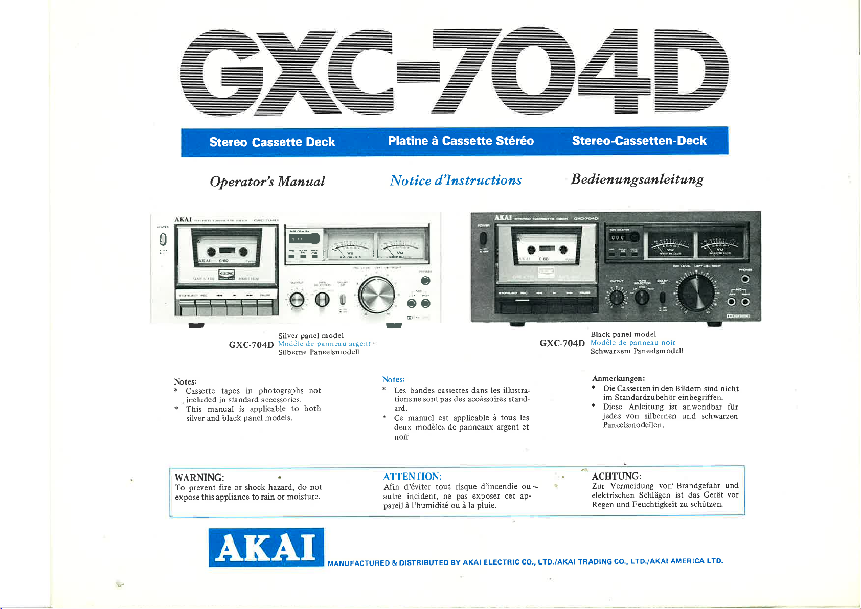
GXC-704D
tapes in
black
fire
photographs
standard accessories.
applicable
is
panel
models.
or
shock
to rain or
hazard,
MønuøI
Ërb
ltr
panel
Silver
de
Modèle
Silberne
Pâneelsmodell
not
to botb
do not
moisture.
model
panneau
argent
Notice
d"Instructions
oo
...
E¡
r
Notes:
*
bandes cassettes dans les illustra-
Les
tionsne sontpas des accéssoi¡es stand-
ard.
*
Ce
deux modàles de
nou
ATTENTION:
Afin d'éviter
autre incident,
pareil
à I'humidité ou à
manuel
est
applicable à
panneaux
tout risque
pas
ne
la
d'incendie ou
exposer
pluie.
tous les
argent
cet ap-
GXC-704D
et
-
Bed,ienungsønleitøng
panel
Black
Modèle dc
Schwarzem
Anmerkungen:
*
+
jedes
ACHTUNG:
Zur
elektrischen Schlägen
Regen und
model
panneau
Die Cassetten in
im
Standardzubehör
Diese Anleitung ist anwendbar ltir
von
Paneelsmo
Vermeidung von' Brandgefahr
noir
Paneelsmodell
den
Bildern sind nicht
einbegriffen.
silbernen und
dellen.
das Gerät
Feuchtigkeit zu schützen.
ist
schwa¡zen
und
vor
<t.
MANUFACTURED
DISTBIBUTEO
&
8Y AKAI
ELECTRIC
CO., LTO./AKAI
TRADING
LTD./AKAI AMERICA
CO,,
LTO.
ù.
.4t
INTRODUCTION
you
Thank
Deck.
the
Only
purchasing
for
togivey
exciuúve
wearfree
entertainment
fidelity
read
Please
tion.
WARNING
Voltage
Poweirequirements
to area.
ensure
Please
your
area.
in
doubt,
If in
120V,60
2201240V,50
ll1ll2Ol22Ol240V,
countries.
Power Cord
your
If
into
insert
machine.
please
use
trician.
FOR CUSTOMERS
wires
The
following
the
Neutral,
Blue:
colours
As the
not
may
terminals
the
wi¡e
The
terminal
wi¡e
The
terminal
*
When
tightened
this
Selection
that
consult
for USA
Hz
Hz
machine
the
you
If
one
in this
code:
correspond
in
which
which
which
which
wiring
and
ma¡rual
of a similar
of
your plug,
marked
is
Akai's
is operated
if it
its
in
for electrical
your
machine
qualified elect¡ician.
a
Canada
and
with
power
to
UK
Hz
inlet
use any
for
comes
AC
want
Europe,
50/60
kind
UK
IN THE
lead
mains
Brown:
in
wi¡es
the
is
is colou¡ed
ma¡ked
a
that
the
with
proceed as
coloured
the
with
brown
with the
plug, ensure
loose strands
no
GXC-704D
entirety
equipment
meets
and Australia
internallv
detachable
a
on
other
and consult
coloured
are
Live
mains lead
the
coloured
must
bl're
letter
letter
that all
Stereo
properly.
you
before
differ
power requirements
the
switchable
power
panel
rear
the
follows:
N or
must
type
a
accordance
in
of this
markings
connected
be
coloured
be connected
or coloured
L
terminals
exist'
of wire
of
Cassette
machine
hAkai's
stics
of high
opera-
start
area
from
for other
cord,
of
power cord,
qualified
aPparatus
identifying
black'
red'
are securely
and
please
your
elec-
with
the
to
the
to
INTRODUCTION
stéréo
éléments
Les
permettant
ment
fonctionner
et de
de
fonctionnement
un
lecture
votre
remerciements
nos
Tous
GXC-704D.
ATTENTION
dist¡ibution
de
Tension
La
pays.
Véìifi"r
Consuìter
120V, 60
220V
I'Australie.
interne
Cordon
Si
brancher
sut
un autie
qualifié.
utilisée
tension
la tension
si
un
Hz
l24OY,
1
pour
les
d'alimentation
appareil
vot¡e
iê'cordon
panneau arrière
le
type
électricien
pour
50
l}V
autres
de
appareil
cet
GXC-704D
aPPareil.
pour
locale
Etats-Unis
les
Hz
20Y
|
I
PaYS'
muni
est
sur
de
cordon
pour I'achat
sont
parfait.
a des
les appareils
correspond
qualifié
pour
220Vl
I
I'entróe
d'alimentation
nécessai¡e.
si
et le Canada.
I'Europe,
240V,
cordon
d'un
d'alimentation
votre appareil.
platine à cassette
la
de
plus
de la
tête
La
caracté¡istiques
électriques
de votre
à celle
Royaume-Uni
le
Hz à
5 0/60
d'alimentation
vous
Si
consulter
quaÌité
haute
d'enregistre-
magné-
sure'
des
Perform-
faites
vous
si
Hli::i#;
varie selon
appareil'
commutation
séparé,
située
secteur
utiliser
voulez
électricien
un
les
et
EINFUHRUNG
Sie
gekauft.
gestellt
haupt
Freide
heiten
Wir
durchzulesen
Es
und
werde
durc
und seine
empfehlen
bevor Sie
e
haben
HINWEISE
Netzspannungen
Netzspannung
Die
die
Wenn
USA,
Europa,
l2Ol220-240V
Netzkabel
Wenn
ihr
Kabeln,
Netzspannung
richtige
es notwendig
Kanada
Grossbrittanien,
Gerat
Ihr
AC
im
fragen Sie
120V
Netzeingang
Verschleißfestigkeit
Ihnen
hangt
(umshaltbar)
eine abnehmbare
um
ist,
60
daher
das
fragen
Hz
Rat
dringend
Gerät
Lokalität
die
zu versiche¡n.
Sie
Australien
50/60
des
bei einem
bereiten'
diese
in Bet¡ieb
an: wir
einem
bei
2201240V
Hz
Netzkabel
Geräts.
Elektriker'
empfehlen
50
einfügen Sie
hat,
Nützung
sorgfältig
Hz
Anleitung
nehmen'
Elektriker
für die anderen
Bei
Ihnen
um Rat'
110-
Länder
anderen
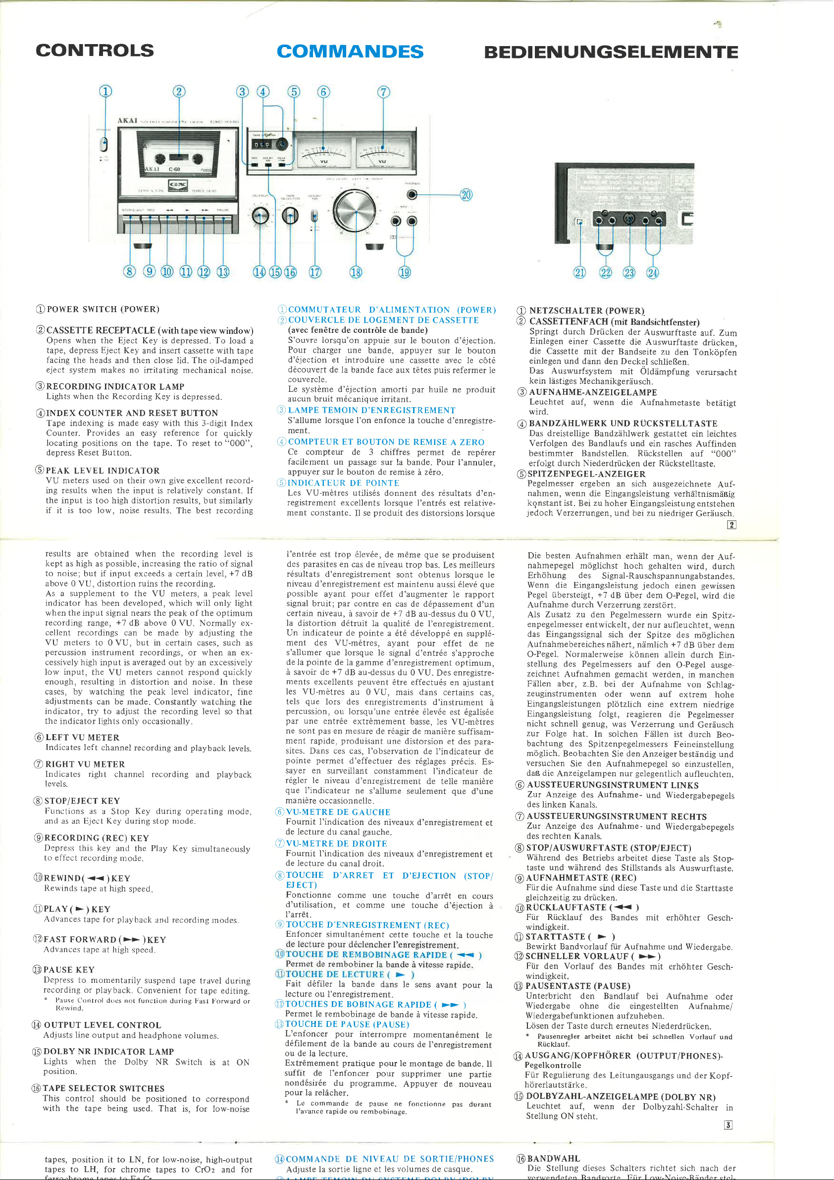
@TAPE
@nolnv
@lnrr+nlcHT
sELEcroR swrrcHEs
This
control should
with the
tapes,
tapes to
ferrochrome
*
Setting
activates
before
precisely
process
noise, thus
*
The
input level
tape being
position
LH, for ch¡ome
RCfCT tO STANDARD
MENDED
When using
necessary
playback
outer
tapes to
TAPES.
NR swITcH
Dolby
the
Dolby
the
are
they
same amôunt
the
eliminates
also
tape
that this switch
also-
ring controls the
and the inner knob
to LN,
it
eliminating tape
recorded with the
REcoRDING
channel recording input
coaxial therefore
ently
together.
or
meters, adjust so
as close to,
*
See also
*
Coaxial controls and
easy fade in
ning of a musical
decrease
@uIcnoruoNE
@up¡,opsoNE
Accommodates
pedance
listening
rupur
@
Set
Set
from
*
When
*
The U.S-4.
@LlNp
Connects
external
@DrN
Can
Jacks
through
+
When
adjusted
*
Tlre U.S.A.
@LINE
Connects
Peak
in volume at the
for
sELEcroR
LINE
to
to DIN
DIN
the
microphones
INPUT
to
soulce.
JACK
used instead
be
for
a DIN
using
with Microphone
OUTPUT
but not
Level lndicator
(gradual
JAcKs
JAcK
stereo
monitoring
for
recording
for
recording
connection.
Model
JACKS
tape
connection
connection
the
Model
JACKS
tape
to
positioned
be
That is,
used.
for low-noise,
tapes
Fe-Cr.
REFERENCE
NR Switch
circuit to
recorded
extraneous
they
Observing
that the meter
exceeding
increase
selection) and
raise
and
during
hiss.
set to
be
LEVEL coNTRoLS
right channel
level. The
be
may
the
0 VU.*
for exceptions.
enumerated
in volume at the begin-
end) recording operations
(left
and right)
headphones
or
swITcH
from the
from
connected,
are
equipped
is not
(left
outputs
of the
Din
not equipped
is
inputs
right)
and
(or
Line
an
with
cord-
Jack, recording
Recording
(Ieft and
external
c,f
to correspond
for low-noiSe
high-output
to CrOz
AND
to ON
low level signals
lowers them by
playback.
and superimposed
processor,
Dolby
ON
controls the
controls
adjusted independ-
left
and
indicators
positions facilitâte
fade out
8 ohms
of
private
the
witlr
with
headphone
connection.
line
microphones
DIN input
the
this
Rec. outputs)
and Output
Input
extelnal
input
Level Controls.
this
right)
amplifier
and
RECOM-
position
position
recording
right
swing
(gradual
is cut'
facilitv'
amplifier
level is
facility'
for
This
it is
left
are
VU
im-
or
;;;ã;J¿.
_
at
of
or
pour
+
Le commande de
I'avance rapide ou
@coutrlll,lDE
Adjuste
LAMPE
@
NR)
S'allume
est enclenché.
QDCOUUUTATEURS
(TAPE
Cette
pondre
bandes à
bandes à
Ies
ferrochrome à
+
Référer
Dtllls
(D
couruurAT¡UR
NR)
Le
enfonce
signaux
avant
cisément
procédé
particulier
*
@cotvtltnNoEs
MENT
La
d'enregistrement
commande
canal
permet
manière
réglage
VU-mètres
oscillent
''
t'
la
et d'affaiblissemetrt
ment-
@PRISES
PRISE DE
@
Adaptée
monitoring
couuuTATEUR
@
Mettre
partir
à
.Mettre sur
partir
à
*
-ã;
;,"""å;;.
la relâcher.
la sortie
TEMOIN
quand
SELECTOR)
commande
la bande
à
faible bruit,
haut rendement
bandes
chrome à
les
circuit DOLBY
l'e commutateur
de
d'être
d'autant
tous
le
Lorsque
système DOLBY
mutateur â
rnolette
I'on utilise
GAUCHE
extérieure commande
le niveau
gauche.
pouvoir
de
indépendante
de telle
de
proximité,
à
Pour les exeptions se
pointe.
commandes
Les
facilitcnt
de
Lorsque
un
puissance
puissance
MICRO
CASQUE
au
ou l'écoute
ìa
sur
de la
la
microphones
des
Ies
pause
rembobinage.
NIvEAU
DE
et les volumes
ligne
DU SYSTEME
le commutateur
DE SELECTION
doit être
utilisée. C'est-à-dire,
FeCr.
BANDIIS
DE sYSl'EME
se trouve
puissance
faible
enregistrés
à la
parasites
les
souffle
la
de bande
est
il
lecture également.
DE
DROIT
->
canal d¡oit
du
commandes
Les
en effectuer
manière
gauche
toutefois
de coâxial
progressif
gairr
sonore au
progressif
sonore à
(MlC)
(PHONE)
casque
de 8 Ohm
DE SELECTEUR
position
connexion "LINE".
position
microphones sont
äñ;î; d;";.ff::i
ne fonctionne
SoRTIE/PHoNEs
DE
de
DOLBY
de système
positionné
positionner
la
faibte
à
CrOz
STANDAIìD
de systeme
pour
lecture.
se trouvent
une bande
nécessaire d'enfoncer
NIvEAU
d'entrée
simultanée.
ou
que,
et de droite,
réféter
et les
(augmentation
début d'une sélection
fin)
la
des
(gauche
individuelle.
"LINE"
"DIN"
ou de
à
bruit
pour
et
llT
DoLBY
alimenté
amplifiés
sont
être réduits très
Au
est
supplimé.
enregistrée
D'ENREGISTRE-
le niveau
et
le bouton
d'enregistrement
coaxiales,
sont
un réglage
en observant
tout
les indicateurs
sans dépasser
russi à
positions
grande
(plus
opérations
et droite)
d'impédance
D'ENTREE
pour
l'enregistrement
pour
I'enregistrement
Ia connexion
hrarrchés,
pas
durant
casque.
(DOLBY
DOLBY
BANDE
DE
pour
corres-
pottr
pour
LN,
à
LH,
pour
les bandes
lìl'l(IOMMAN-
(DoLBl
lorsque
DOLBY,
juste
cours de
éliminés
et
avec
ce com-
d'entrée
intérieur
ce
d'une
Procéder
0 VU.*
l'indicâteur
énumérées
graduelle
nrusicale)
dimi¡rution
d'enregistrc-
pour
"DIN".
l'entrée
"l)lN"
les
les
I'on
les
pré-
qui
au
les
en
de
ce
le
dc
de
le
rur Ì(egulrerung
oes
Lellurìgausgângs
und der
hörerlautstärke.
DoLBYZAHL-ANZETGELAMpE
@
Leuchtet auf, wenn der Dolbyzahl-Schalter
Stellung ON steht.
@nr¡¡ownul
Die Stellung
verwendeten Bandsorte.
len Sie
bänder
Ferrochrom-Bânder
für
Siehc
"
TEN.
DOLBYZAHL-SCHALTBR
@
Niederdrücken
durch
Pegel
mittlerem
Dadurch
vom Rauschpegel
Wiedergabe wi¡d
der
durch
soweit
unhörbar
*
Für
genommenen Bândern
ebe falls
RECHTS
@
TROLLE
Mit dem
gangspegel
der des
koaxial und
sind
nander oder
bachten Sie
stellen Sie
zu 0 schwingen,
ebenfalls
Sie
nahmefällen
+
Beobacltten
nah
*
Koaxiale
liinblend-(graduellc
Musi kwahl
gegen
rigkeite
dieses Schalters
Für Low-Noise-Bänder
für rauscharme
ihn auf
auf
REIrI,RENZ-
LN,
für Chrom-Bänder
LH,
der
auf
UND ITMPFOHLENE
Taste
die Dolby-Schaltung
der Aufnahme
bei
und hohem
Abstand der
der
ist
entgegengesetzt
eine
kompensiert,
wird.
Wiedergabe
die
in
Stellung
.>
äußeren Ring
des
linl<en Kanals
zusammen
den
so ein, dae
den
im
nten.
Sie
Kontrollen und
und
)
Iìnde)
Aufnahme-Bedienung
n
.
Bandes
des
die
daß
von im
ist es
(niedergedrückt)
ON
LINKS
rechten,
AUFNAHMEPEGEL-KON-
und mit dem
reguliert.
können
linken und
die
jedoch
Auge.
nicht
Spitzenpegelmesser
den Maximunr-wertzeiger
Lautstärkenzunahme
Abblencl-(gröBere
@UTTRoroNANScHLUSSBUcHSEN
fechts)
und
KoPFHöRERBUcHSE
8E
Für den
zum Mithören
zu hören.
rrncnxc-wAHLTASTE
@
Drücken Sie
LINE-
Drücken Sie
Mìkrophon
+
Anschluß eines 8-Ohm-Stereokopfhörers
des Aufnahmetons
die Taste
Anschluss.
die Taste
oder DIN-AnschÌuss.
N4ikropltone atrgcschlosscrl
die
Wenn
l'iingang îusgcschNl
(PHoNE)
zu
zu
tet.
@RcA-STScKEREINGANG
rechts)
Anschließen
Zum
Ausgãnge)
von
an Tonbandausgänge
Tonquellen.
(DoLBy
richtet sich
Hochleistungs-
auf
Fe-Cr.
(DOLBY
DOLBY
die
mehr
Pegel
NR)
NR bewirkt,
als die
mit
Signale mit
Signale
verstärk werden.
niedrigen
geworden.
größer
Wirkung
dieser
wirkende
Bandrauschen
das
Dolby-Vèrfahren auf-
notwendig, den Schalter
wird
zu
der
Aufnahme-Ein-
inneren Knopf
Diese Kontrollen
unabhängig
daher
eingestellt werden. Beo-
¡echten Pegelmesser
über
möglichst
hinaus. Halten
0
Anz-eiger
wegen Aus-
Abz¿jhlstellungen
zu
L¿utstärken
ohne
iegliche
(MIC) (links
oder um ungestört
für
LINE
DIN
Aufnahmen
für Aufnahmen
(LINE
IN)
sind,
KopÏ-
NR)
in
E
nach der
stel-
und
CrOz,
BANDSOR-
daß
kleinem
Signalpegel
Bei
Anhebung
Schaltung
nahezu
bringen'
vonei-
und
nahe
wegen Aus-
ermögliclten
einer
Beginrr
zunahme
Schwie-
vom
von
l)lN-
ist
(links
und
(oder
Rec-
tr
CONTROLS
COMMANDES
BEDIENUNGSELEMENTE
@rowrn
cnsS¡rrE
Ø
Opens
tape, depress
facing
eject
swrrcH
when
the heads
system makes no
@npconuNG
Lights when
@INnnx
Tape indexing is made
Counter.
locating
depress Reset Button.
@p¡,rr
VU meters used on
ing results
the input is too high distortion
if
results
kept
to noise;
above 0
As a supplement to the
indicator has
when the input signal nears
recording
cellent
couNTER AND RESET BUTToN
Provides
positions
LEVEL rNDrcAToR
is
it
too
are obtained
high
as
but if input exceeds a certain level,
VU,
range,
recordings can
(PowER)
RECEPTACLE
Eject
the
Eject
Key and inse¡t cassette with
and then close lid. The oil-damped
Key
(with
is
tape
depressed. To
irritating mechanical noise.
INDIcAToR LAMP
the Recording Key is depressed-
easy with
this 3-digit
an easy reference for
on
the tape. To reset to
give
when the
low,
noise results.
possible,
as
disto¡tion
own
their
input
when the
increasing
ruÍns the recording.
excellent record-
is relatively
results, but similarly
The best recording
recording
the
VU meters,
been developed, which
+'7
dB above
peak
the
0 VU. No¡mally
be made by adjusting the
VU meters to 0 VU, but in certain cases,
percussion
cessively high
low input,
enough, resulting
cases, by watching
adjustments
indicator, try to adjust
the indicator lights only occasionally.
@LEFT
Indicates
nrcur vu
@
lndicates right
levels.
sror¡rrrcr KEY
@
F-trnctions
antl as
@nnconorNc
Depress
to effect
instrument
input is
the
VU
in distortion
can be
VU
METER
left channel
METER
channel recording
as
a Stop
lrject Key during
an
(REc)
this key
recording
and
mode.
recordings, or when an ex-
averaged
meters cannot respond
the
made. Constantly watching
recording
Key during
out
and
peak
level
recording level
the
and
nrode.
stop
by
operating mode,
KEy
Play
the
Key
@nnwrNol<<)KEY
Rewinds
tape at
high
speed
6)plrv(>)KEY
Advances
6Ðrrsr
Advances
@rnuse
l)epress
recording
*
ourrur LEVEL coNTRoL
@
Adjusts
@DOLBY
Lights
p
osition.
@TAPE
This
with
tape for
FoRwARDI>>)KEy
tape at high
ruv
to monlentarily
or
(lontrol
Pause
lìewi n
d.
line
NR
when
sELEcroR
control
the
tape being
playback
speed.
playback.
does not
output and
Convenient
function
headphone
INDICATOR
the Dolby NR
swrrcHES
should be
used. That
and recording
suspend tape
for tape editing.
during Fast
volumes.
LAMP
Switch
positioned
is,
view window)
load
Index
quickly
"000",
constant.
level is
ratio of signal
+7
peak
a
will
of
the optimum
an excessively
noise.
level
only light
such as
quickly
these
In
indicator, fine
so that
playback
and
simultaneously
to
for
levels.
piayback
modes.
travel during
!'orward
is
at ON
correspond
low-noise
tape
dB
ex-
the
or
a
If
@counrurATEUR
.,)COUVERCLE
(avec
fenêtre
S'ouvre lorsqu'on
Pour
charger une
d'éjection
découvert
couvercle-
Le
système d'éjection
aucun
bruit
uttpp rEMorN
@
S'allume
ment.
(f
courrruR ET
Ce compteur
facilement
appuyer
@tnotc,rreuR
Les VU-mètres utilisés
registrement excellents
ment constante.
I'entrée est
parasites
des
résultats
niveau
d'enregistrement
possible
signal
bruit;
certain
la
niveau,
distortion
Un indicateur
ment des
s'allumer
pointe
de la
à savoir de
ments excellents
les
VU-mètres
que
tels
percussion,
par
une entrée
ne sont
pas
ment rapide,
sites.
Dans ces cas, I'observation
pointe
permet
sayer en
régler le
que
f indicateur
manière
@vu-nrrnE
Fournit
de lecture
@vu-lrrrnE
Fournit
de
lecture
@TOUCHE
EJ
ECT)
Fonctionne
d'utilisation,
l'arrêt.
(9¡
ToucuE
Enfoncer
Fait
défiler
lecture
ou 1'enregistrement.
@roucu¡s
Permet
6ÐTOUCHE
L'enfoncer
défilement
ou de la lecture.
Extrêmement
le
suffit de
nondésirée
pour
la
relâcher.
{'
Le commande
l'avance rapide
DE LOGEMENT DE
de contrôle de
et
introduire une cassette
de 1a
bande face
mécanique
lorsque I'on enfonce
de 3 chiffres
passage
un
le
su¡
bouton de remise
DE
trop
en
cas de
d'enregistrement
pour
ayant
par
à savoir de
détruit la
de
VU-mètres,
que
lorsque
de Ia
+7
dB au-dessus
au
lo¡s des enregistrements
ou lorsqu'une entrée
en
mesure de réagir
produisant
d'effectuer
suweillant
niveau
occasionnelle.
DE
cAUcHE
I'indication
du canal
DE DRorrg
I'indication
du canal droit.
D'ARRET
comme une
et
D'EN
REGISTREM
simultanément
la
bande dans
DE BoBTNAGE
rembobinage
DE PAUSE (PAUSE)
pour
de la
pratique
I'enfoncer
programme.
du
ou
D'ALTMENTATToN
CASSETTE
bande)
appuie
sur le bouton d'éjection.
bande,
appuyer sur le bouton
par
puis
huile
aux têtes
amorti
irritant.
D'ENREGISTREMENT
la touche d'enregistre-
BouroN DE REMTSE
permet
sur la
bande. Pour i'annuler,
zêro.
à
PotNTE
donnent des résuÌtats
lorsque 1'entrés
produit
se
Il
é1evée,
effet
contre en
pointe
gamme
peuvent
0 VU, mais dans
ext¡èmement
constamment
d'en¡egistrement
ne
s'allume
des niveaux
gauche.
des niveaux d'enregistrement
comme une
interrompre
bande
pour
pause
de
rembobinage-
des distorsions
de même
niveau
que
trop bas.
sont obtenus
est
maintenu
d'augmenter
cas
de dépassement
+7
¿3
qualité
a été développé
ayant
le signal
d'enregistrement
au-dessus du
de I'enregistrement.
pour
d'entrée
du
VU.
0
être effectués
d'instrument
élevée est
basse, les
de maniè¡e
une
distorsion et
de f
des
réglages
l'indicateur
de
seulement
d'enregistrement
ET
D'EJECTION (STOpi
touche d'arrêt
touche
(REC)
ENT
cette
touche et
le
sens avant
RAITDE
de
bande
à vitesse
au cours
pour
momentanément
de I'enregistrement
le montage
supprimer
Appuyer
ne
fonctionne pas
se
Les meilleurs
aussi
effet
Des
certains
indìcateur de
telle manière
d'éjection
(
>>
de nouveau
(powlR)
avec le côté
refermer
produit
ne
A zERo
de
repérer
d'en-
est relative-
lorsque
produisent
lorsque le
que
élevé
le rapport
d'un
0
VU,
en supplé-
de ne
s'approche
optimum,
enregistre-
en
ajustant
cas,
égalisée
VU-mètres
suffisam-
para-
des
précis.
que
rapide.
de bande.
une
d'une
en cours
la
touche
pour
)
partie
durant
Es-
de
et
et
la
le
ll
urrzsculLTER
@
CISSETTENFACH (mit
Ø
Springt durch
Einlegen
die
Cassette
le
einlegen
Das Auswurfsystem
kein
lâstiges
nunuluME-ANzETcELAMpE
@
Leuchtet
wìrd.
BANDZÄHLWERK UND
@
Das dreistellige Bandzählwerk
Verfolgen des Bandlaufs
bestimmter
erfolgt durch Niederdrücken
SPTTzENPEGEL-ANzEIGER
@
Pegelmesser
nahmen,
kgnstant ist.
jedoch
Die besten
nahmepegel
Erhöhung des
Wenn die
Pegel übersteíEt,
Aufnahme
Zusatz zu
Als
enpegelmesser
das
Eingangssignal
Aufnahmebereiches
O-Pegel. Normalerweise
stellung des Pegelmessers
zeichnet
Fäl1en
zeuginstrumenten
à
Eingangsleistungen
Eingangsleistung
nicht schnell
zur
Folge hat.
bachtung des
möglich.
versuchen
dan die
AUSSTEUERUNGSINSTRUMENT
@
@
€)
@AUFNAHMETASTE
à
@RÜCKLAUFTASTE
@srARTTAsrE(
Anzeige
Zur
des
linken
AUSSTEUERUNGSINSTRUMENT
Zur Anzeige
des rechten Kanals.
srop/AUSwURFTASTE (srop/EJEcr)
Während
und
taste
Für
die Aufnahme
gleichzeitig
Für Rücklauf
windigkeit.
Bewirkt
@scHNBnER
Für
den Vorlauf
windigkeit.
PAUSENTASTE
@
Unterbricht
Wiedergabe
'Wiedergab
Lösen der Taste durch
*
Pausenregler
Rücklauf.
AUSGANG/KOpFHöRER
@
Pegelkontrolle
Für
Regulierung
hörerlautstärke.
DOLBYZAHL-ANZETGELAMpE
@
Leuchtet
Stellung
(PowER).
D¡ücken
einer
Cassette
mit
und dann
der Bandseite
den Deckel
mit Öldämpfung
Mechanikgeräusch.
auf,
wenn die
Bandstellen.
ergeben
wenn die
Bei
Verzerrungen,
Aufnahmen
möglichst
Eingangsleistung
durch
an sich ausgezeichnete
Eingangsleistung verhältnismäßig
zu
hoher
und bei zu
hoch
Signal-Rauschspannungabstandes.
+7
dB über dem
Verzerrung zerstört.
den
Pegelmessern
entwickelt,
sich der
nähert, nämlich
Aufnahmen
aber,
z.B.
gemacht
bei der
oder
plötzlich
folgt,
genug,
was
In soichen FäIIen
Spitzenpegelmessers
Beobachten
Sie
Anzeigelampen nur
des Aufnahme-
Kanals.
des Aufnalme-
des Betriebs
während
zu drücken.
Sie
den
Aufnahmepegel so einzustellen,
arbeitet
des Stillstands
(REC)
sind diese
(<
des Bandes
>
Bandvorlauf
)
Aufnahme und Wíedergabe.
für
voRLAUF
des Bandes mit
(PAUSE)
den Bandlauf
ohne die
efunkt
ionen auf zuheb en.
erneutes Niederdrücken.
arbeitet nicht
des
Leitungausgangs und
auf,
wenn
ON
steht.
der Dolbyzahl-Schalter
Bandsichrfenster)
der
Auswurftaste
die
Auswu¡ftaste
zu
schließen.
Aufnahmetaste
RÜCKSTELLTASTE
gestattet
und ein rasches
Rückstellen
Rückstelltaste.
der
auf. Ztm
drücken,
den Tonköpfen
verursacht
betãtigt
ein
leichtes
Auffinden
auf "000"
Auf-
Eingangsleistung entstehen
niedriger
erhält
man,
gehalten
jedoch
der nur
aufleuchtet,
Spitze des
können
allein durch
auf den
werden,
Aufnahme von
wenn auf extrem
eine
reagieren
Verzerrung und
den
Anzeigerbeständig und
gelegentlich
Geräusch.
wenn der
wird, durch
gewissen
einen
O-Pegel, wird die
wurde ein
+7
O-PegeI ausge-
exttem
die
ist
Feineinstellung
Spitz-
wenn
möglichen
dB
über dem
ín
manchen
Schlag-
hohe
niedrige
Pegelmesser
Geräusch
durch
Beo-
aufleuchten.
LINKS
und Wiedergabepegels
RECHTS
und Wiedergabepegels
diese Taste
als Auswurftaste.
Taste und
)
mit erhöhter
>>)
(
erhöhter
Aufnahme
bei
die
als
Stop-
Starttaste
Gesch-
Gesch-
oder
eingestellten Aufnahmei
bei schnellen Vorlauf
(OUTpUT/pHONES)-
der
Kopf-
(DOLBy
NR)
E
Auf-
Ein-
und
in
E
position
tapes,
tapes
to
€---^,.h-^-^ +^^^- +^ Tì- /ì-
it to LN, for low-noise, high-output
LH,
for chrome
tapes to CrOz and
for
@coruvanDE
Adjuste
la so¡tie ligne
DE NTvEAU
et les volumes de casque.
DE
soRTrE/pHoNEs
@BANDwAHL
Die
Stellung
r¡o¡rr¡en¡lefen Rcndcnrfa |liir T nrr¡-J\lnicn-Rärrdor cfol-
dieses
Schalters
richtet
sich nach der
 Loading...