

Page 1
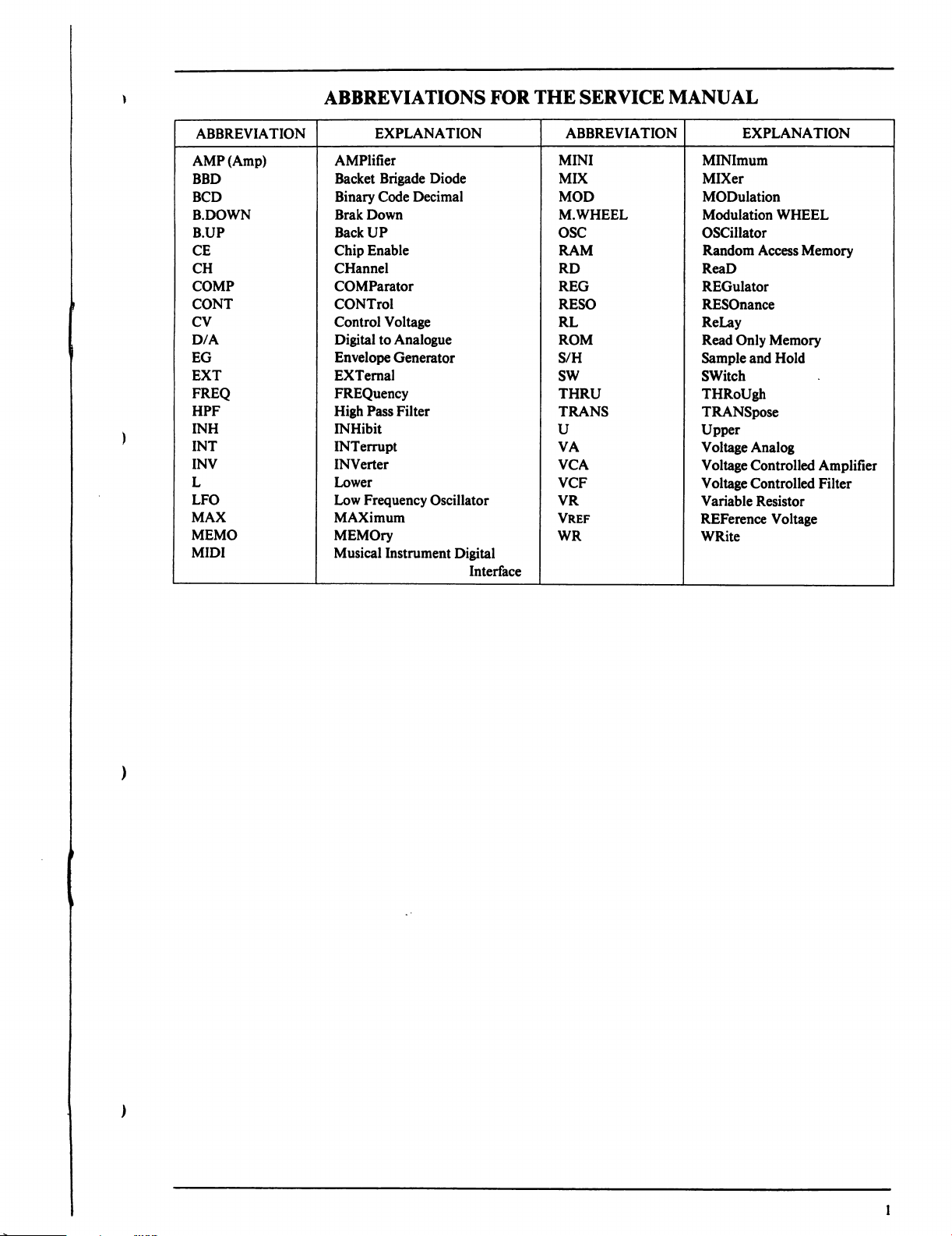
ABBREVIATIONS
FOR
THE
SERVICE
MANUAL
Page 2
SAFETY
INSTRUCTION
SAFETY
Confirm
greater
[C]
headphone
PRECAUTIONS
1.
2.
4.
CHECK
the
specified
than
10
Mohms,
or
[a]i
specified
jacks,
line-in-out
DURING
Parts
identified
Replace
In
addition
applying
Examples:
Use
specified
1)
Wires
2)
Double
3)
High
Use
specified
1)
Insulation
2)
PVC
3)
Spacers
4)
Insulation
5)
Plastic
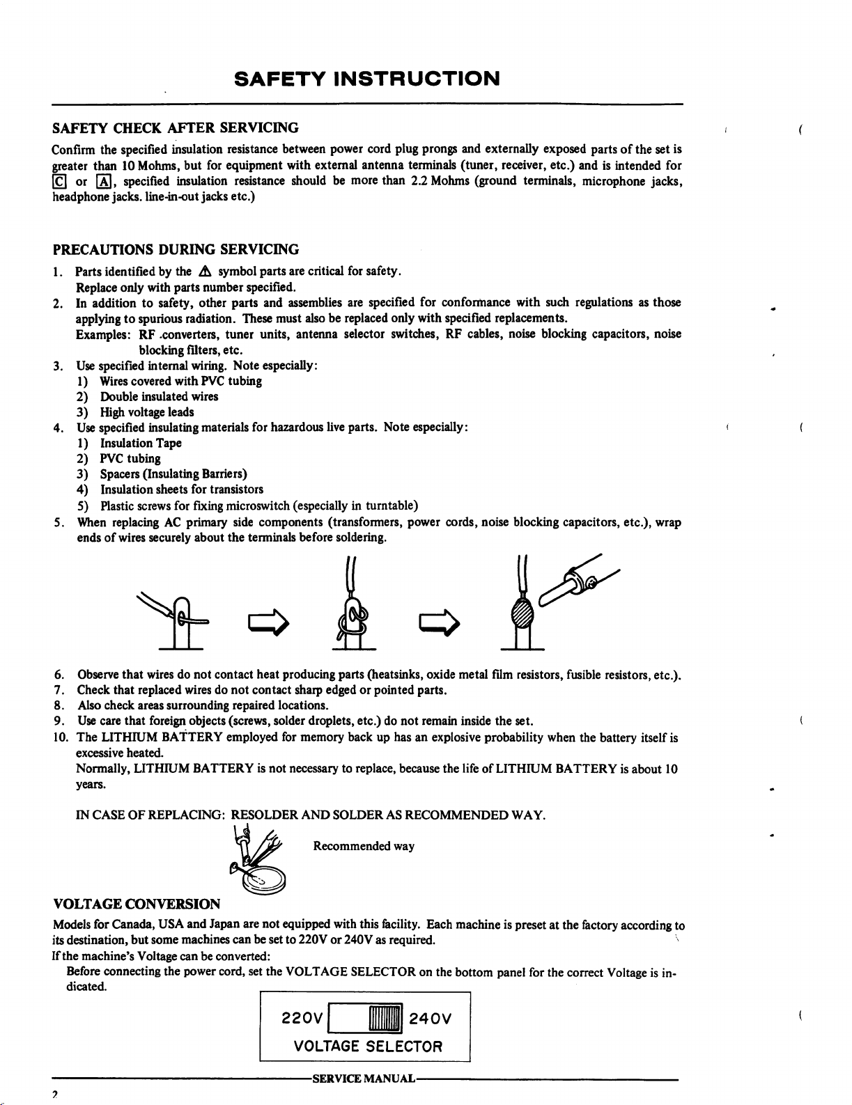
When
replacing
ends
of
by
only
with
to
safety,
to
spurious
RF
.converters,
blocking
internal
covered
insulated
voltage
insulating
Tape
tubing
(Insulating
sheets
screws
AC
wires
securely
AFTER
leads
SERVICING
insulation
but
insulation
resistance
for
equipment
between
resistance
jacks
etc.)
SERVICING
the A symbol
parts
number
other
radiation.
filters,
wiring.
with
PVC
wires
materials
Barriers)
for
transistors
for
fixing
primary
about
parts
specified.
parts
and
These
must
tuner
units,
etc.
Note
especially:
tubing
for
hazardous
microswitch
side
components
the
terminals
power
cord
with
external
should
are
critical
assemblies
also
antenna
(especially
before
antenna
be
more
than
for
safety.
are
specified
be
replaced
selector
live
parts.
(transformers,
soldering.
only
switches,
Note
in
turntable)
plug
prongs
and
terminals
2.2
with
especially:
power
(tuner,
Mohms
for
(ground
conformance
specified
RF
cables,
cords,
noise
externally
exposed
receiver,
terminals,
with
such
parts
etc.)
and
microphone
regulations
is
replacements.
noise
blocking
blocking
capacitors,
capacitors,
of
the
set
is
intended
for
jacks,
as
those
noise
etc.),
wrap
6.
Observe
7.
Check
8.
Also
9.
Use
10.
The
excessive
Normally,
years.
IN
VOLTAGE
Models
its
destination,
If
the
Before
dicated.
that
wires
that
replaced
check
areas
care
that
foreign
LITHIUM
heated.
LITHIUM
CASE
OF
REPLACING:
CONVERSION
for
Canada,
but
some
machine's
Voltage
connecting
do
not
contact
wires
do
not
contact
surrounding
objects
BATTERY
USA
and
machines can
can
the
power
repaired
(screws,
employed
BATTERY
RESOLDER
Japan
are
be
be
converted:
cord,
set
heat
producing
sharp
edged
locations.
solder
droplets,
for
memory
is
not
necessary
AND
Recommended
not
equipped
set
to
220V
or
the
VOLTAGE
VOLTAGE
-SERVICE
parts
(heatsinks,
or
pointed
etc.)
do
not
back
up
has
to
replace,
SOLDER
with
240V
SELECTOR
because
AS
RECOMMENDED
way
this
facility.
as
required.
SELECTOR
MANUAL-
oxide
metal
parts.
remain
inside
an
explosive
the
Each
on
the
probability
life
of
machine
bottom
film
resistors,
the
set.
LITHIUM
WAY.
is
preset
panel
fusible
when
BATTERY
at
the
for
the
correct
resistors,
the
battery
itself
is
about
factory
according
Voltage
is
etc.).
is
10
to
in
Page 3
SECTION
1
SERVICE
I.
SPECIFICATIONS
II.
DISMANTLING
1.
HOW
TO
2.
HOW
TO
3.
HOW
TO
III.
CONTROLS
IV.
THE
KEYBOARD
FREQUENCIES
V.
PRINCIPAL
VI.
ADJUSTMENT
1.
BALANCE
2.
OFF-SET
3.
BALANCE
4.
OFF-SET
VII.
PC
VIII.
MIDI
BOARD
TITLES
IMPLEMENTATION
TABLE
OF
UNIT
OPEN
THE
FRONT
DISMANTLE
DISMANTLE
THE
THE
REACTION-SHIP
AND
PARTS
OF
±6V
OF
FINAL
OF
BBD
OF
IC6
LOCATION
ON
THE
VCA
ON
OUTPUT
(LF
356)
ON
AND
IDENTIFICATION
CHART
MANUAL
OF
CONTENTS
PANEL
KEYBOARD
BEND
PANEL
TO
MUSICAL-NOTATION
POWER
THE
VOICE
ON
THE
THE
CPU
BLOCK
EQUALLY
SUPPLY
CHORUS
PC
TEMPERED
PC
PC
BOARD
PC
BOARD
NUMBERS
BOARD
BOARD
4
5
5
5
5
6
SCALE
7
7
8
8
8
9
9
10
10
This
Mannal
is
available
produced
LTD.,
Tokyo,
FOR
to
unauthorized
in
any form
Japan.
INTERNAL
personal.
without
-SERVICE
USE
No
permission
MANUAL-
ONLY
and
part
from
most
of
this
manual
AKAI-ELECTRIC
not
be
may
made
be
re
CO.,
Page 4
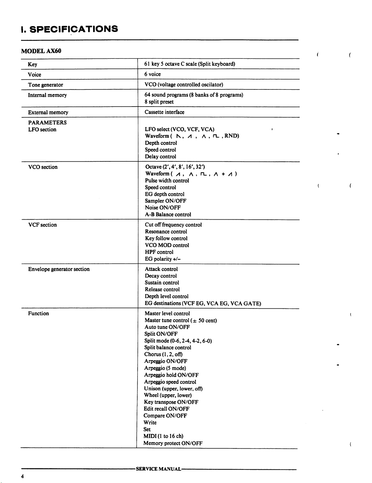
I.
SPECIFICATIONS
MODEL
AX60
-SERVICE
MANUAL-
Page 5
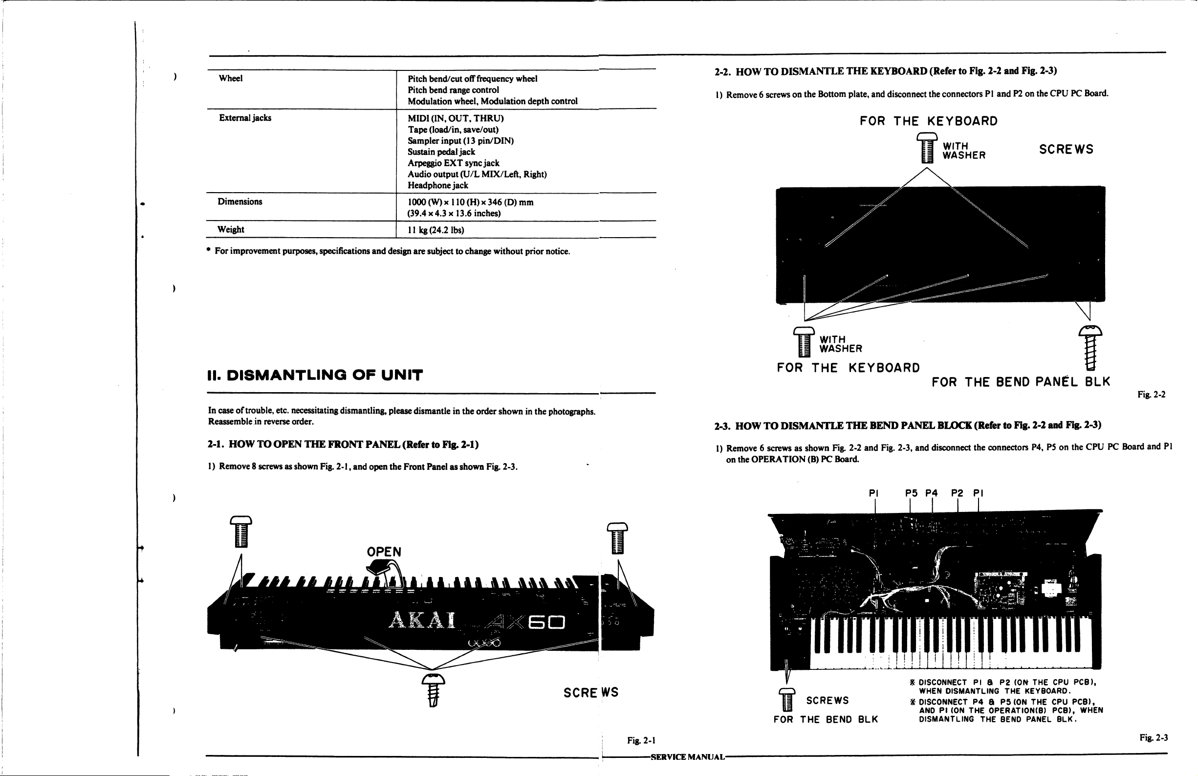
2-2.
HOW
TO
DISMANTLE
1)
Remove 6 screws
on
the
THE
Bottom
plate,
KEYBOARD
and
disconnect
(Refer
the
to
Fig.
2-2
and
connectors
PI
and
P2
Fig.
2-3)
on
the
CPU
PC
Board.
*
For
improvement
II.
DISMANTLING
In
case
of
trouble,
Reassemble
purposes,
etc.
necessitating
in
reverse
order.
specifications
dismantling,
and
OF
design
are
UNIT
please
dismantle
subject to
change
in
the
without
order
shown
prior
notice.
in
the
photographs.
2-3.
HOW
FOR
TO
DISMANTLE
THE
FOR
THE
KEYBOARD
THE
BEND
PANEL
KEYBOARD
FOR
THE
BLOCK
(Refer
BEND
to
SCREWS
PANEL
Fig.
2-2
and
BLK
Fig.
2-3)
Fig.
2-2
2-1.
HOW
1)
Remove
TO
OPEN
8 screws
as
shown
THE
Fig.
FRONT
2-1,
and
PANEL
open
the
(Refer
to Fig.
Front
Panel
2-1)
as
shown
Fig.
2-3.
SCREWS
1)
Remove 6 screws
on
the
OPERATION
as
FOR
shown
Fig.
(B)
PC
Board.
SCREWS
THE
BEND
2-2
and
PI
BLK
Fig.
2-3,
P5
and
disconnect
P4
DISCONNECT
WHEN
DISCONNECT
AND
PI
DISMANTLING
the
P2
PI
PI 8 P2
DISMANTLING
P4 8 P5
(ON
THE
connectors
OPERATION(B)
THE
BEND
P4,
(ON
THE
THE
KEYBOARD.
(ON
THE CPU
PANEL
P5
on
the
CPU
PCB),
PCB),
PCB),
WHEN
BLK.
CPU
PC
Board
and
PI
Fig.
2-1
SERVICE
MANUAL-
Fig.
2-3
Page 6
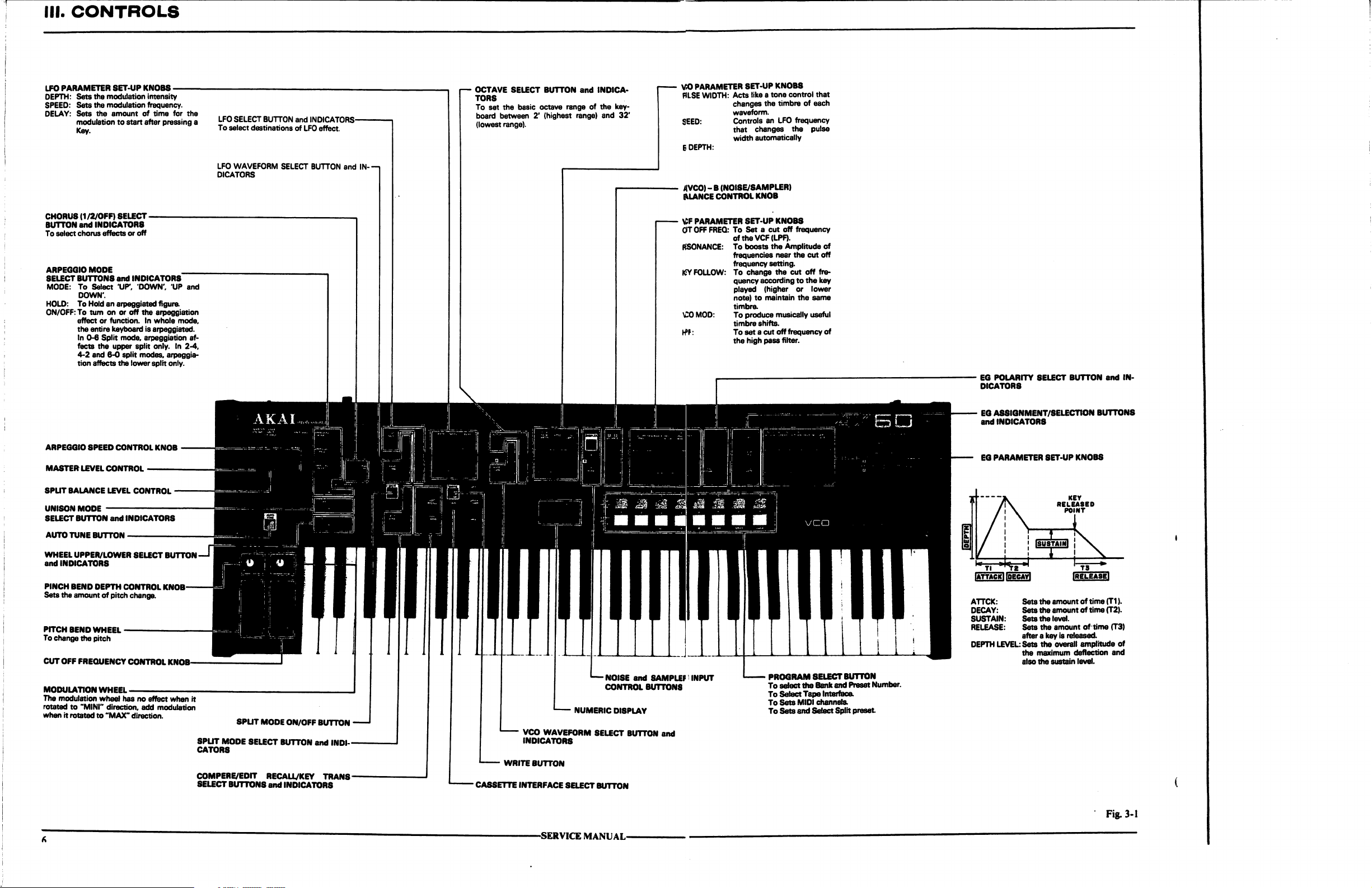
III.
CONTROLS
LFO
PARAMETER
DEPTH:
Sets
SPEED:
Sets
DELAY:
Sets
modulation
Key.
SET-UP
the
modulation
the
modulation
the
amount
to
KNOBS
intensity
frequency.
of
time
start after
for
pressing
the
a
LFO
SELECT
To
select
LFO
DICATORS
BUTTON
destinations
WAVEFORM
and
INDICATORS-
of
LFO
effect.
SELECT
BUTTON
and
IN
OCTAVE
TORS
To
board
(lowest
SELECT
set
the
between
range).
BUTTON
basic
octave
2'
(highest
and
range
of
range)
INDICA
the
key
and
32'
VCO
PARAMETER
PJLSE
WIDTH:
SEED:
E
DEPTH:
AVCO) -B
EUANCE
(NOISE/SAMPLER)
CONTROL
SET-UP
Acts
changes
waveform.
Controls
that
width
KNOBS
tike a tone
control
the
timbre
an
LFO
changes
automatically
KNOB
that
of
each
frequency
the
CHORUS
BUTTON
To
ARPEGGIO
SELECT
MODE:
HOLD:
ON/OFF:
ARPEGGIO
MASTER
SPUT
UNISON
SELECT
AUTO
(1/2/OFF)
and
select
chorus
MODE
BUTTONS
To
Select
DOWN'.
To
Hotd
To
turn
effect
the
entire
In
0-6
fects
4-2
tion
SPEED
LEVEL
BALANCE
MODE
BUTTON
TUNE
and 6-0
affects
BUTTON-
SELECT
INDICATORS
effects
an
on
or
function.
keyboard
Split
the
upper
CONTROL
LEVEL
and
-
or
off
and
INDICATORS
'UP*,
DOWN',
arpeggiated
or
off
the
arpeggiation
In
whole
is
arpeggiated.
mode,
arpeggiation
split
only.
split
modes,
the
lower
split
CONTROL
KNOB
CONTROL
INDICATORS
UP
and
figure.
mode,
af
In
2-4.
arpeggia
only.
v:f
parameter
GTT
OFF
FREQ:
To
RESONANCE:
ICY
FOLLOW: To
CO
MOD:
I-PF:
oftheVCF(LPF).
To
frequencies
frequency
quency
played
note)
timbre.
To
timbre
To
the
setup
knobs
Set a cut
boosts
change
produce
set a cut
high
off
the
Amplitude
near
setting.
the
according
(higher
to
maintain
musically
shifts.
off
pass
filter.
frequency
of
the cut
off
cut
off
fre
to
the
key
or
lower
the
same
useful
frequency
of
EG
POLARITY
DICATORS
EG ASSIGNMENT/SELECTION
and
INDICATORS
EG
PARAMETER
SELECT
BUTTON
SET-UP
and
BUTTONS
KNOBS
IN
WHEEL
UPPER/LOWER
and
INDICATORS
PINCH
BEND
Sets
the
PITCH
To
change
CUT
OFF
MODULATION
The
modulation
rotated
when
DEPTH
amount
of
BEND
WHEEL
the
pitch
FREQUENCY
WHEEL
wheel
to
"MINI"
it
rotated
direction,
to
"MAX"
SELECT
CONTROL
pitch
change.
—
CONTROL
has
no
effect
add
direction.
BUTTON
KNOB
KNOB
when
modulation
it
SPUT
CATORS
COMPERE/EDIT
SELECT
SPLIT
MODE
MODE
SELECT
BUTTONS
ON/OFF
BUTTON
BUTTON
RECAUJKEY
and
and
INDICATORS
TRANS
INDI
-
WRITE
-
CASSETTE
INTERFACE
NUMERIC
VCO
WAVEFORM
INDICATORS
BUTTON
SELECT
-SERVICE
MANUAL-
—
NOISE
CONTROL
DISPLAY
SELECT
BUTTON
BUTTON
and
SAMPLE! I INPUT
BUTTONS
and
PROGRAM
To
To
To
To
select
the
Select
Tape
Sets
MIDI
Sets
and
Select
SELECT
BUTTON
Bank
and
Preset
Interface.
channels.
Split
preset
Number.
ATTCK:
DECAY:
SUSTAIN:
RELEASE:
DEPTH
LEVEL:
Sets
the
amount
Sets
the
amount
Sets
the
level.
Sets
the
amount
after a key
Sets
the
also
is
the
overall
maximum
the
sustain
of
time
(T1).
of
time
(T2).
of
time
released.
deflection
level.
(T3)
amplitude
of
and
Fig.
3-1
Page 7
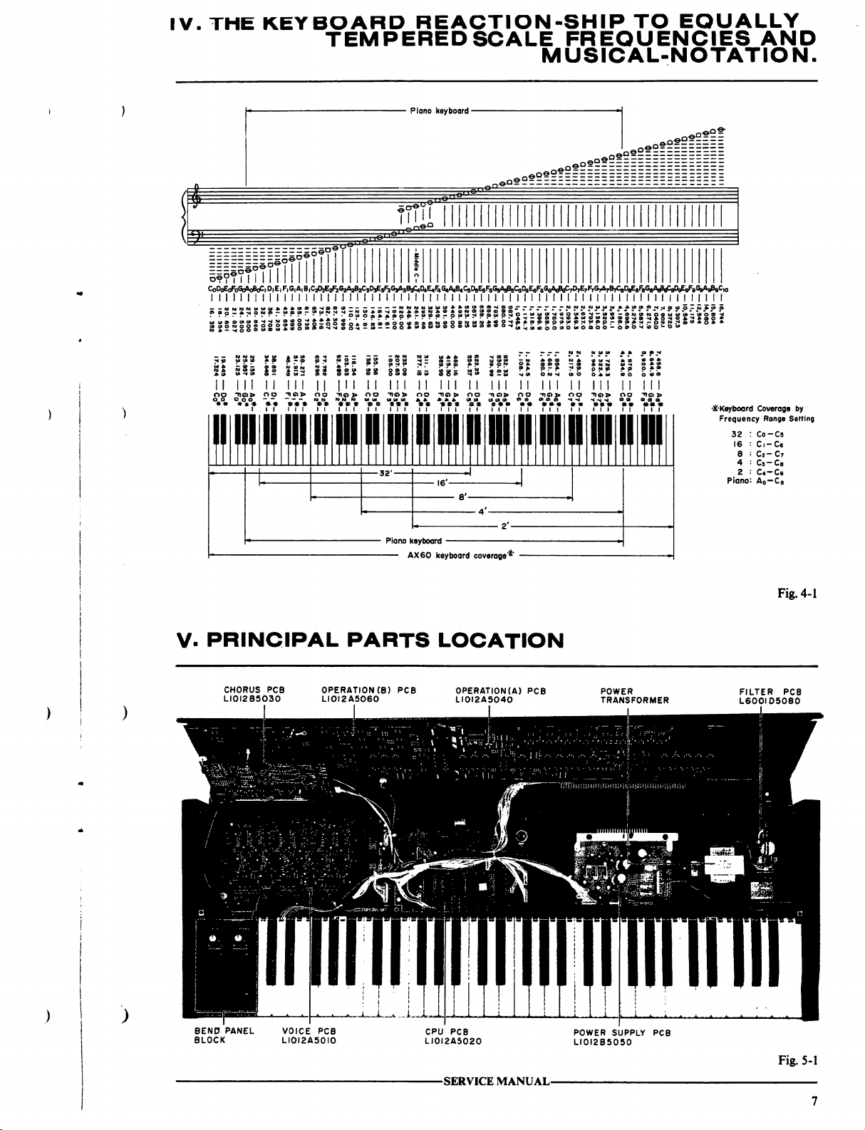
IV.
THE
KEYBOARD
TEMPERED
REACTION-SHIP
SCALE
-
Piano
keyboard
-
mil
»e?1
ii??°
PfffTtTT
CoD<^oFoGoMoClD,ElF,61A)B1CAEaF262A2B2C303E3F3G3A3B3C,CU^F4MAC9D9E9F9G5As%
I I I I I I I I I I I I I
.»
SSSS
II
III
no
"no>
oo
I I I I I I I I
!
* 5 & S -
8 2 S 5 3 = » 5 15 ^ 5 £ ♦ S «
»S*SoS*«°**5o*°S--oo*wae»t5o5i*o*»«o«Hj,^ul|0^00,ow0ffl00_owo^«oo-tow
SIS
*^S
S^
II
III
||
ico
oo
I I I I I
So=
|ll
^i<
g«
II
I I
I I I I I I I I
£8g
n
III
IS
I I
* S * S 5 S S S 2
m
ii
I I I I I I I I I I I I I I I I I
S g " "
" " " "
in
y!»it
TO
FREQUENCIES
EQUALLY
AND
MUSICAL-NOTATION.
oeofE
in
"-"
I I I I I I I I I I
-M-N
-ro-w-l--w
-*
i-
in
ii
mi
*??
*•
\i
m
ii i ii
I I
"-"** ? fPr???
».•--*
| I I I
•^Keyboard
?
Coverage
Frequency
32
Co-Cs
16
C.-Ce
8
C2-C7
4
Cj-Ca
2
C4-C9
Piano
Range
Setting
by
V-
PRINCIPAL
CHORUS
LIOI2B5O3O
PCB
PARTS
OPERATION
LIOI2A5O6O
(B)
LOCATION
PCB
OPERATION(A)
LI0I2A5040
PCB
POWER
TRANSFORMER
Fig.
4-1
FILTER
L600I05080
PCB
-SERVICE
MANUAL-
POWER
SUPPLY
LI0I2BS050
PCB
Fig.
5-1
Page 8
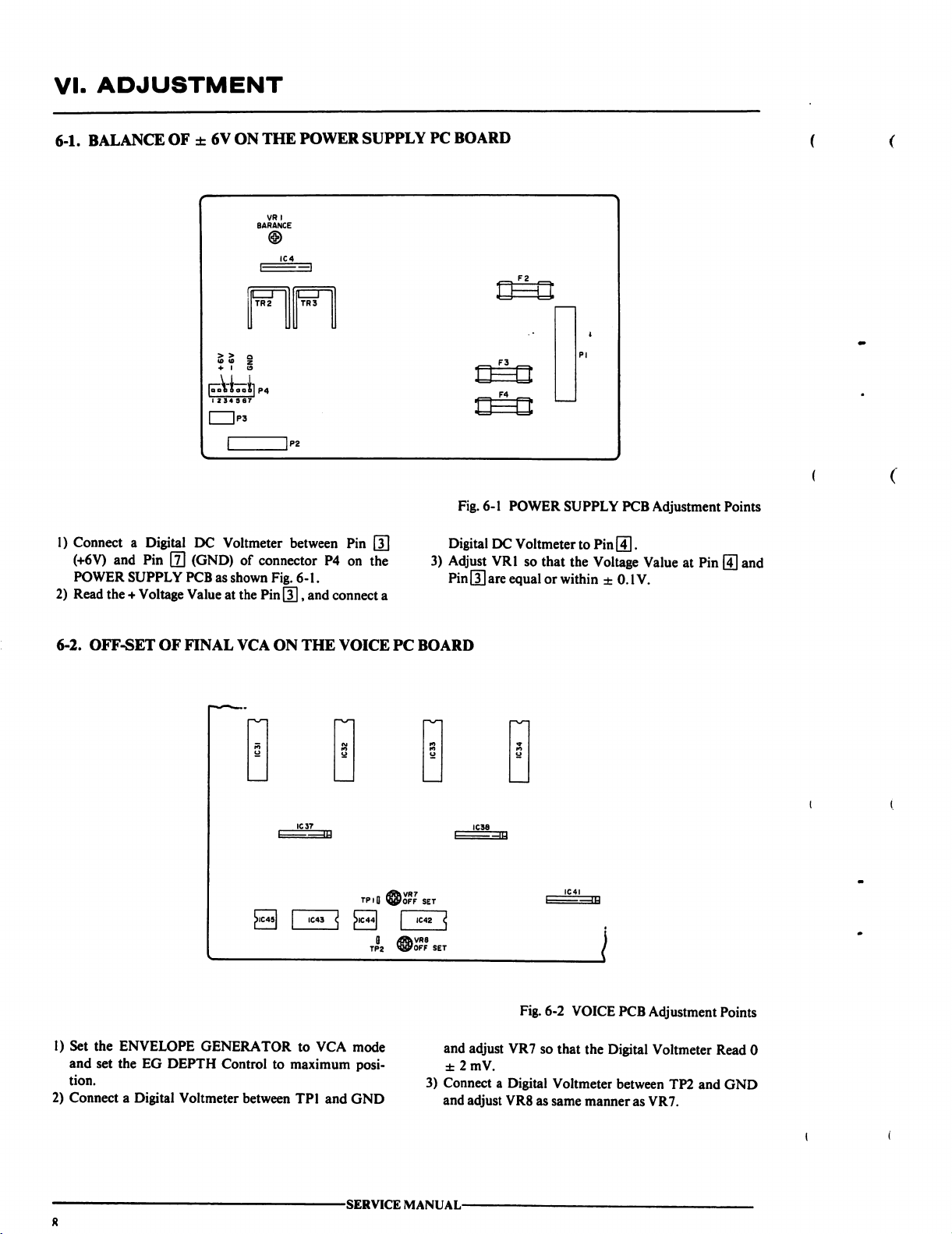
VI.
ADJUSTMENT
6-1.
BALANCE
OF ± 6V
ON
THE
POWER
SUPPLY
PC
BOARD
Fig.
6-1
POWER
SUPPLY
PCB
Adjustment
Points
1)
Connect
(+6V)
and
POWER
2)
Read
the + Voltage
6-2.
OFF-SET
a
Digital
DC
Voltmeter
Pin 0 (GND)
SUPPLY
PCB
Value
OF
FINAL
as
shown
at
between
of
connector
Fig.
the
Pin
VCA
ON
P4
6-1.
[T|,
and
connect
THE
VOICE
Pin
[T]
on
the
a
TP.O
piC44
0
TP2
PC
<J
FOFF
JiVRS
J/OFF
Digital
3)
Adjust
Pin
GQ
BOARD
SET
IC42
SET
DC
Voltmeter
VRI
so
are
equal
to
that
the
or
within
Pin
[4].
Voltage
Value
±
0.1V.
at
Pin
|
land
1)
Set
the
ENVELOPE
and
set
the
EG
DEPTH
tion.
2)
Connect a Digital
GENERATOR
Control
Voltmeter
to
between
to
VCA
mode
maximum
TP1
posi
and
GND
-SERVICE
and
adjust
±2mV.
3)
Connect a Digital
and
adjust
VR8
MANUAL-
Fig.
6-2
VR7
so
that
Voltmeter
as
same
VOICE
PCB
the
Digital
between
manner
Adjustment
Voltmeter
TP2
as
VR7.
Points
Read 0
and
GND
Page 9
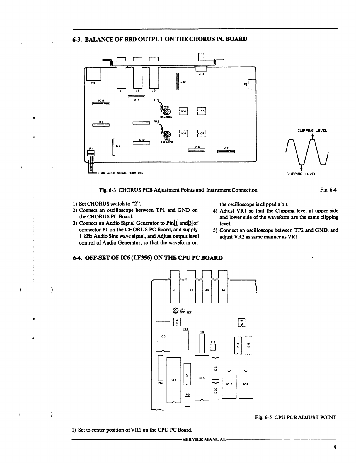
6-3.
BALANCE
OF BBD
OUTPUT
ON
THE
CHORUS
PC
BOARD
■ I kHz
Fig.
1)
Set
CHORUS
2)
Connect
the
3)
Connect
connector
1
control
an
CHORUS
an
PI
kHz
Audio
of
Audio
J2
J3
ICI3
IC10
I
AUDIO
SIGNAL
FROM
OSC
6-3
CHORUS
switch
oscilloscope
PC
Board.
Audio
Signal
on
the
CHORUS
Sine
wave
Generator,
PCB
to
"2".
between
Generator
PC
signal,
and
so
that
TPI
>IC4l > IC5
>
ice I >
VR2
BALANCE
Adjustment
TPI
to
Board,
Adjust output
the
Points
and
GND
on
Pin
[I]
and||]
of
and
supply
level
waveform
on
ic9
I
and
Instrument
the
4)
Adjust
and
level.
5)
Connect
adjust
•L
Connection
oscilloscope
VR1
lower
VR2
is
clipped
so
that
the
Clipping
side
of
the
waveform
an
oscilloscope
as
same
between
manner
CLIPPING
a
bit.
as
VR1.
CLIPPING
LEVEL
level
are
the
TP2
and
LEVEL
Fig.
at
upper
same
clipping
GND,
6-4
side
and
6-4.
OFF-SET
OF
IC6
(LF356)
ON
THE
\
/off
CPU
VR
I
set
PC
BOARD
□
Fig.
6-5
CPU
PCB
ADJUST
POINT
1)
Set
to
center
position
of
VR1
on
the
CPU
PC
Board.
SERVICE
MANUAL-
Page 10
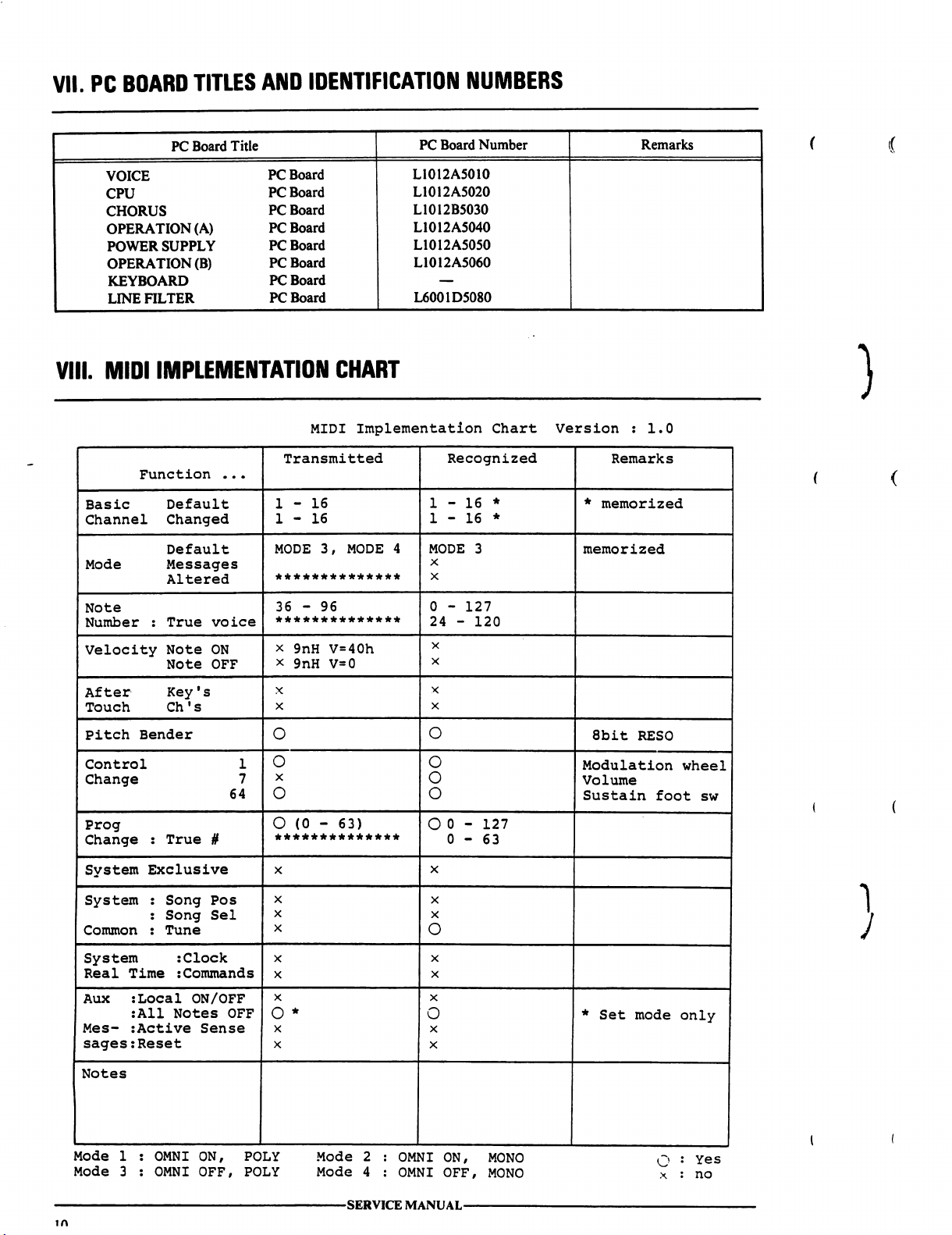
VII.
PC
BOARD
TITLES
AND
IDENTIFICATION
NUMBERS
VIII.
MIDI
IMPLEMENTATION
CHART
MIDI
Implementation
Chart
Version : 1.0
Mode 1 :
Mode 3 :
OMNI
OMNI
ON,
POLY
OFF,
POLY Mode
Mode
2
4
-SERVICE
OMNI
ON,
OMNI
OFF,
MANUAL-
MONO
MONO
Yes
no
Page 11
SECTION
2
RECOMMENDED
1.
PC
BOARD
2.
VOICE
3.
CPU
4.
CHORUS
5.
OPERATION
6.
OPERATION
7.
POWER
8.
FILTER
9.
PANEL
10.
ASSEMBLY
11.
FINAL
INDEX
BLOCK
PC
BOARD
PC
BOARD
PC
SUPPLY
PC
BOARD
BEND
BLOCK
ASSEMBLY
PARTS
TABLE
SPARE
BOARD
(A)
(B)
PARTS
PC
BOARD
PC
BOARD
PC
BOARD
BLOCK
BLOCK
OF
CONTENTS
LIST
LIST
13
14
14
14
14
14
14
15
15
15
17
17
18
This
Manual
is
available
produced
LTD.,
Tokyo,
FOR
to
unauthorized
in
any
form
Japan.
INTERNAL
personal.
without
USE
No
permission
-PARTS
ONLY
part
from
LIST-
and
must
not
be
of
this
manual
AKAI-ELECTRIC
may
be
made
CO.,
re
11
Page 12
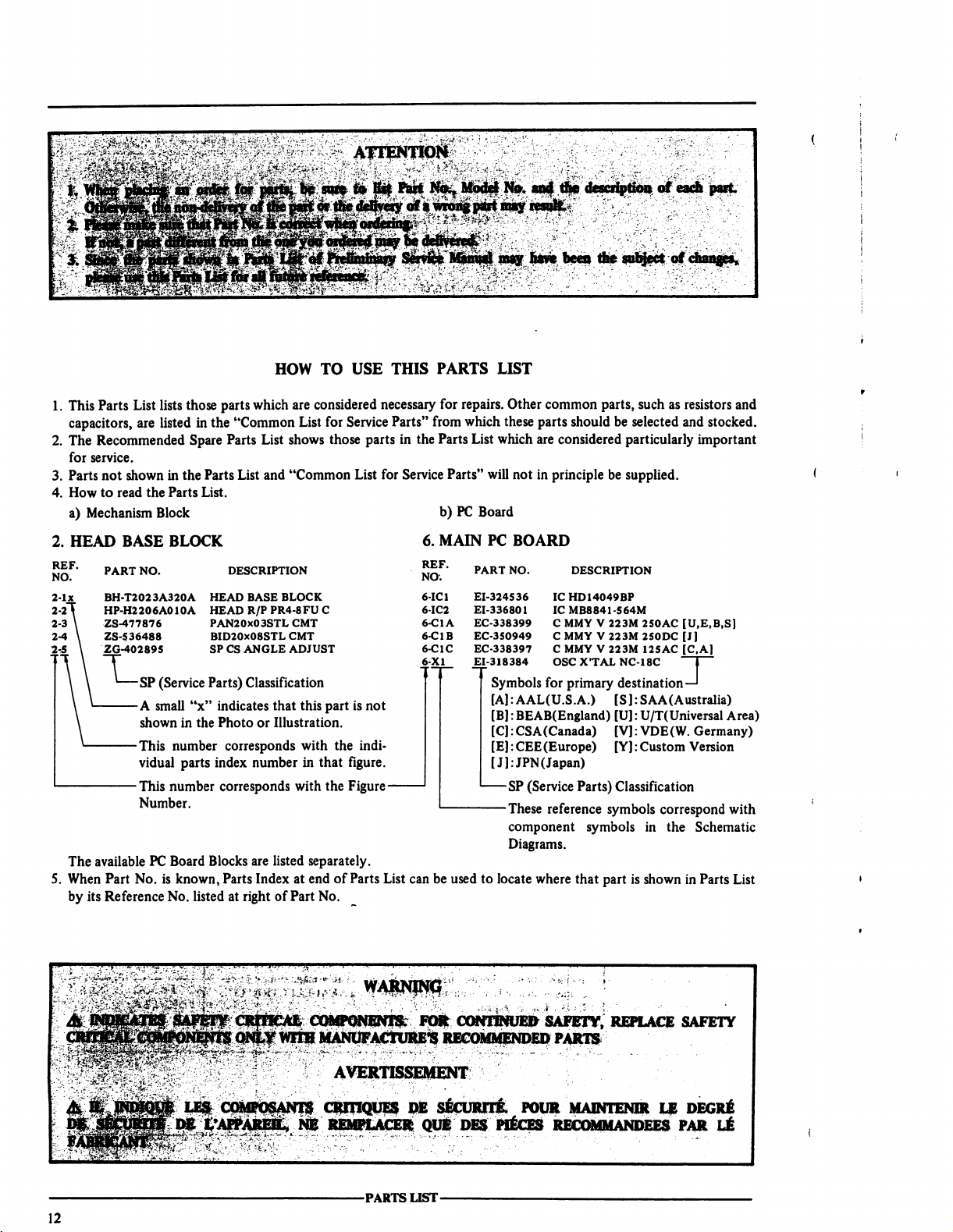
1.
This
Parts
List
lists
capacitors,
2.
The
for
3.
Parts
4.
How
a)
Mechanism
2.
HEAD
are
listed
Recommended
service.
not
shown
to read
the
Block
BASE
those
parts
in
the
Spare
Parts
in
the
Parts
Parts
List.
BLOCK
HOW
which
are
"Common
List
List
List
shows
and
"Common
TO
USE
THIS
considered
for
those
necessary
Service
Parts"
parts
in
the
List
for
Service
6.
PARTS
for
repairs.
from
which
Parts
List
Parts"
will
b)
PC
Board
MAIN
PC
LIST
Other
common
these parts
which
not
should
are
considered
in
principle
BOARD
parts,
such
as
resistors
be
selected
particularly
be
supplied.
and
stocked.
important
and
The
available
5.
When
by
its
PART
NO.
BH-T2023A320A
HP-H2206A010A
ZS-477876
ZS-5
36488
2G-402895
'—SP
(Service
A
small
"x"
shown
in
the
This
number
vidual
parts
This
number
Number.
PC
Board
Part
No.
is
known,
Reference
No.
listed
DESCRIPTION
HEAD
BASE
HEAD
PAN20X03STL
BID20X08STL
SP
CS
Parts)
indicates
Photo
corresponds
index
corresponds
Blocks
Parts
at
BLOCK
R/P
PR4-8FU
CMT
CMT
ANGLE
ADJUST
Classification
that
this
or
Illustration.
with
number
are
Index
right
in
that
with
listed
separately.
at
end
of
Part
No.
At
COMPONENTS.
WTIH
MANUFACTURE'S
C
part
is
not
the
indi
figure.
the
Figure-
of
Parts
List
can
FOR
Symbols
[A]:
[B]:
[C]:
[E]:
[J]:JPN(
—SP
—These
be used
to
locate
CONTINUED
for
AAL(U.S.A.)
BEAB(England)
CSA(Canada)
CEE(Europe)
Japan)
(Service
reference
component
Diagrams.
where
SAFETY,
RECOMMENDED
primary
destination—!
[S]:
SAA
[U]:
U/T(Universal
[VJ:
VDE(W.
[Y]:
Custom
Parts)
Classification
symbols
symbols
that part
in
is
shown
REPLACE SAFETY
PARTS
(Australia)
Area)
Germany)
Version
correspond
the
with
Schematic
in
Parts
List
12
LBS
COMPOSANTS
DE
t'APPAREIL,
AVERTISSEMENT
CRITIQUES
NE
REMPLACER
-PARTS
OB
QUE
LIST-
SECURTlt
DES
FOUR
PIECES
RECOMMANDEES PAR
MAINTENIR
LE
DEGRE
LE
Page 13
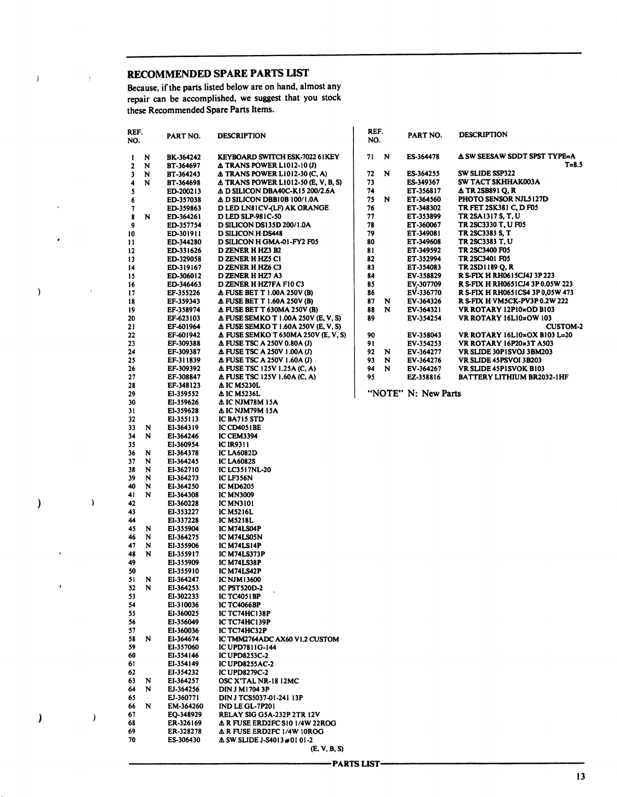
RECOMMENDED
Because,
repair
these
if
the
parts
can
be
accomplished,
Recommended
SPARE
listed
Spare
PARTS
below
are
we
suggest
Parts
Items.
LIST
on
hand,
that
almost
any
you
stock
REF.
NO.
N
1
N
2
N
3
N
4
5
6
7
8
N
9
10
11
12
13
14
IS
16
17
18
19
20
21
22
23
24
25
26
27
28
29
30
31
32
33
34
35
36
37
38
39
40
41
42
43
44
45
46
47
48
49
50
51
52
53
54
55
56
57
58
59
60
61
62
63
64
65
66
67
68
69
70
PART
NO.
BK-364242
BT-364697 A TRANS
BT-364243 A TRANS
BT-364698 A TRANS
ED-200213
ED-357038 A D
ED-359863 D LED
ED-364261 D LED
ED-357754 D SILICON
ED-301911 D SILICON H DS448
ED-344280 D SILICON H GMA-01-FY2
ED-331626 D ZENER H HZ3
ED-329058 D ZENER H HZ5
ED-319167 D ZENER
ED-306012 D ZENER
ED-346463 D ZENER H HZ7FA
EF-355226 A FUSE
EF-359343 A FUSE
EF-358974 A FUSE
EF-623103 A FUSE
EF-601964 A FUSE
EF-601942 A FUSE
EF-309388 A FUSE
EF-309387 A FUSE
EF-311839 A FUSE
EF-309392 A FUSE
EF-308847 A FUSE
EF-348123
EI-359552
EI-359626 A IC
EI-359628 A IC
EI-355113
EI-364319
N
EI-364246
N
EI-360954
EI-364378
N
EI-364245
N
N
EI-362710
N
EI-364273
EI-364250
N
EI-364308
N
EI-360228
EI-353227
EI-337228
El-355904
N
N
EI-364275
N
EI-355906
N
EI-355917
EI-355909
EI-3559I0
EI-364247
N
N
EI-364253
EI-302233
EI-310036
EI-360025
EI-356049
EI-360036
N
EI-364674
EI-357060
EI-354146
EI-354149
EI-354232
N
EI-364257
N
EJ-364256
EJ-360771
N
EM-364260
EQ-348929
ER-326169 A R
ER-328278 A R
ES-306430 A SW
DESCRIPTION
KEYBOARD
SWITCH
POWER
POWER
POWER
AD
SILICON
DBA40C-K15
SILICON
DBB10B
LN81
CV-(LF)
SLP-981C-50
DS135D
HHZ6C3
HHZ7
BET T 1.00A
BET T 1.60A
BET T 630MA
SEMKO T 1.00A
SEMKO T 1.60A
SEMKO T 630MA
TSC A 250V
TSC A 250V
TSC A 250V
TSC
125V
TSC
AICM523OL
AIC
ICBA715STD
ICCD4051BE
ICCEM3394
1C1R9311
IC
LA6082D
IC
LA6082S
ICLC3517NL-20
IC
LF356N
ICMD6205
IC
MN3009
ICMN3101
ICM5216L
ICM5218L
IC
M74LS04P
ICM74LS05N
ICM74LS14P
ICM74LS373P
ICM74LS38P
ICM74LS42P
ICNJM13600
ICPST520D-2
ICTC4051BP
ICTC4066BP
IC
TC74HC138P
IC
TC74HC139P
ICTC74HC32P
IC
TMM2764ADC
ICUPD7811G-144
IC
UPD8253C-2
IC
UPD8255AC-2
ICUPD8279C-2
OSC
DINJM1704
DIN J TCS5O37-OI
IND
RELAY
125V
M5236L
NJM78M
NJM79M
X'TAL
NR-18
3P
LE
GL-7P201
SIG
G5A-232P
FUSE
ERD2FC
FUSE
ERD2FC
SLIDE
J-S4OI3#O1
15A
15A
ESK-7022
L1012-10
(J)
L1012-30
L1O12-5O
(C,
(E,
200/2.6A
100/1.0A
AK
ORANGE
200/1.0A
F10
C3
250V
250V
250V
250V
250V
0.80A
1.00A
1.60A
1.25A
(C,
1.60A
(C,
V1.2
F05
(B)
(B)
(B)
250V
(J)
(J)
(J)
A)
A)
CUSTOM
B2
Cl
A3
AX60
12MC
-241
13P
2TR
12V
S10
1/4W
1/4W
10ROG
01-2
(E,V,B,S)
61KEY
A)
V,
B, S)
(E,
V,
S)
(E,
V,
S)
(E,
V,
22ROG
-PARTS
S)
"NOTE"
LIST-
N:
New
Parts
13
Page 14
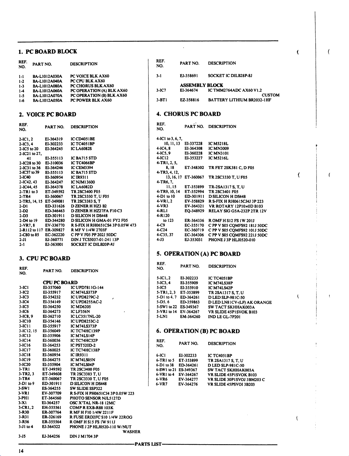
1.
PC
2.
VOICE
BOARD
PC
BOARD
BLOCK
REF.
NO.
3-1
PART
NO.
EJ-358691
ASSEMBLY
3-IC7
3-BT1
4.
REF.
NO.
4-IClto3,6,7,
4-IC4,8
4-IC5.9
4-IC12
4-TR1.2.5,
4-TR3.4,12,
4-TR6,
4-TR9,10,14
4-D1
4-VR1.2
4-VR3
4-RL1
4-R120
4-C9
4-C24
4-C35,37
4-J3
EI-364674
EZ-358816
CHORUS
PART
10,11,13
8,18
13,16,17
11,15
to
to
EI-337228
EI-364308
EI-360228
EI-353227
ET-348302
ET-360067
7,
ET-353899
ET-352994
10
ED-301911 D SILICON H DS448
EV-358829 R S-FIX H RH0615CJ4J
EV-364321
EQ-348929
123
ER-364336
EC-355170
EC-360719 C PP V S05
EC-364306 C PP V S05
EJ-353031
PC
DESCRIPTION
SOCKET
IC
BLOCK
IC
TMM2764ADC
BATTERY
LITHIUM
BOARD
NO.
DESCRIPTION
ICM5218L
IC
MN30O9
ICMN3101
ICM5216L
TR
FET
2SK381
TR
2SC333O
TR-2SA1317
TR2SC3401F05
VR
ROTARY
RELAY
SIG
ROMFHS12
CPPVS05CQMFS92
PHONE J 3P
CQMFS92
CQMFS92
DILB28P-8J
AX60
V1.2
CUSTOM
BR2032-1HF
C, D F05
T, U F05
S,
T,
U
3P
12P10x0D
G5A-232P
FS
HLJ0520-010
B103
2TR
1W
201J
181J50DC
101J
221J
223
12
V
50DC
50DC
3.
CPU
PC
BOARD
5.
OPERATION
(A)
PC
BOARD
14
Page 15

7.
POWER
REF.
NO.
SUPPLY
PART
NO.
PC
BOARD
DESCRIPTION
9.
PANEL
BEND
BLOCK
POWER
7-IC1
7-IC2
7-IC3
7-IC4
7-TR1.3
7-TR2
7-TR4to6
7-D1
7-D2
7-D3,5,
7-D4
7-D7
7-D9,11
7-D13
7-VR1
7-FR1.2
7-R1
7-R2
7-R3
7-R4
7-R5
7-R6
7-R7
7-C1
7-C2,
7-1
7-2
7-F2
7-F2A
7-F2B
7
F2C
7-F3,4
7-F3A.4A
7-F3B.4B
7-F3C.4C
EI-359552
EI-359626 A IC
EI-359628 A IC
EI-348123
ET-356817 A TR
ET-354083 A TR
ET-360067
ED-200213
ED-357038
6,12
ED-357754 D SILICON
ED-319167
ED-306012 D ZENER H HZ7
ED-329058 D ZENER H HZ5
ED-301911 D SILICON H DS448
EV-364326 R S-FIX H VM5CK-PV3P
ER-328278 A R
ER-360725 A ROMFHS12
ER-360732 R MF H F10
ER-356113
ER-356259 R MF H F10
ER-341577
ER-305128 R MF H F10
ER-364324 R MF H F10
EC-322804 C EC V CUT
3
EC-316231 C EC V CUT
EZ-200473
ZW-632226
ASSEMBLY
EF-311839 A FUSE
EF-308847 A FUSE TSC
EF-601964 A FUSE
EF-359343 A FUSE
EF-309387 A FUSE
EF-309392 A FUSE TSC
EF-623103 A FUSE
EF-355226 A FUSE
SUPPLY
PC
BOARD
AIC
M5236L
NJM78M15A
NJM79M15A
AICM5230L
2SB891
Q,
2SD1189
TR
2SC3330
AD
A D
DZENER H HZ6
RMFHF10
RMFHF101/4W7501F
SILICON
WASHER
T, U F05
SILICON
SILICON
FUSE
DBA40C-K15
DBB10B
DS135D
ERD2FC 1 /4W
1/4W
1/4W
1/4W
1/4W
1/4W
SM
SM
RUBBER
INSULATOR
BLOCK
TSC A 250V
125V
SEMKO T 1.60A
BET T 1.60A
TSC A 250V 1 .OOA
125V
SEMKO T 1
BET T 1
R
Q,
R
200/1.0A
C3
A3
Cl
FS
1W
4301G
13O2G
33O1G
15O2F
1402G
472M
222M
35.0DC
SHEET
1.60A
1.60A
250V
1.25A
.OOA
.OOA
250V
200/2.6
100/1.0
A
0.2W
222
10ROG
221J
16.0DC
TC-30
(BUSH
M)
(J)
(C,
A)
250V
(E,
V,
(B)
(J)
(C,
A)
250V
(E,
V,
(B)
A
S)
S)
8.
FILTER
REF.
NO.
8-FL1
8-C2.3
8-C4
8-F1
8-F1A
8-FIB
8-F1C
PC
BOARD
PART
NO.
DESCRIPTION
FILTER
EO-360068
EC-358450 A C
EC-338411 A C CE V FZ
ASSEMBLY
EF-309388 A FUSE
EF-309392 A FUSE
EF-601942 A FUSE
EF-358974 A FUSE
PC
BOARD
BLOCK
COIL
LF
LF-2
CE V B
TSC A 250V
TSC
SEMKO T 630MA
BET T 630MA
I02M
B
400AC
103P
400AC
125V
1.25A
0.80A
(J)
(C,
A)
250V
250V
(B)
(E,V,S)
-PARTS
LIST-
15
Page 16

ASSEMBLY
BLOCK
15
14 I 2
17
SW902
16
-PARTS
LIST-
A(SW90l)
1
!
i
'
Page 17

FINAL
10.
npr
£q
ASSEMBLY
ASSEMBLY
PART
BLOCK
BLOCK
NO.
DESCRIPTION
11.
FINAL
ASSEMBLY
BLOCK
10-1
10-1A
10-1B
10-IC
10-1D
10-2
10-2A
10-3
10-4
10-5
10-6
10-7
10-8
10-9
10-10
10-11
10-12
10-13
10-14
10-15
10-l6x
10-17
10-T901
10-T901A
10-T901B
10-SW901
10-SW902
I0-J90U
EW-524845 A AC
EW-358858 A AC
EW-359641 A AC
EW-358631 A AC
EW-358630 A AC
EZ-631945
EZ-302906
SA-332850
ZS-344754
ZS-362286
ZS-341960
BK-364242
ZS-354230
ZS-201778
ZW-274026
ZW-273914
ZW-698308
ZS-411232
ZW413267 N FRANGE
ZW-273892
ZS-350934
ZS-355511
BT-364697 A TRANS
BT-364243 A TRANS
BT-364698 A TRANS
ES-306430 A SW
ES-364478 A SW
EJ-358633 A SOCKET
CORD 2 CORES
CORD 2 CORES
CORD 2 CORES
CORD 2 CORES
CORD 2 CORES
STRAIN
RELIEF
STRAIN
RELIEF
ROUND
FOOT
ST
PAN30x06STL
PT
BID40x
ST
KEYBOARD
BID50x08STL
PAN40x08STL
SW50
SW40
RV
BID40xl0STL
TW40
PT
BID30x06STLBNI
18STL
BID40x06STL
NYL3OxO55
40STL
(TRANS
BR3OxO8STL
POWER
POWER
POWER
SLIDE
J-S4013#01
SEESAW
INLET
VM1165B,
KP-11
SJTAWGI8UC(C,A)
KJM19C/KS-17
KS-17
KP56O
SR-4N-4
SR-6N-4
CMT
BCM
BNI
SWITCH
ESK-7002
BNI
BNI
BL
BNI
(TRANS
CMT
(TRANS
POWER
BNI
(E,
L1012-10
L1O12-3O
L1012-50
SDDT
SPST
SOT017
VFFJ(J)
(E,V)
LTBS2FBS(B)
LTSA2F
KS17S(S)
(J)
(C,
A)
CO80
(FOOT
FIX)
61KEY
POWER
FIX)
POWER
FIX)
V.
FIX)
B,
S)
(SW90!
FIX)
(J)
(C,
A)
(E,
V,
B, S)
01-2
(E,V,B,S)
TYPE
=A
T=8.5
2P
(E,
V,
B,
S)
■PARTS
LIST-
17
Page 18

AX60
INDEX
-PARTS
LIST-
Page 19

AX60
-PARTS
LIST-
19
Page 20

MEMO
20
Page 21

AKAI
MODEL
SECTION3
SCHEMATIC
AND
TABLE
1.
POWER
2.
CONNECTION
3.
CONTROL
4.
VOICE
5.
CPU
6.
CPU
7.
VOICE
8.
VOICE
9.
OPERATION
10.
OPERATION
11.
CHORUS
12.
CHORUS
13.
LOCATION
PC
BOARD
DIAGRAM
BLOCK
AND
CHORUS
DIAGRAM
PC
BOARD
PC
BOARD
DIAGRAM
DIAGRAM.
(A),
DIAGRAM
PC
BOARD
OF
ICs
DIAGRAM
(B)
PC
AX60
DIAGRAM
PC
BLOCK
BOARD.
BOARD
OF
CONTENTS
DIAGRAM
,
••••
m
....
3
>•••
4
....
5
....
6
....
7
8
.....
9
10
...11
...12
,.13
,.14
This
Manual
is
available
produced
LTD.,
Tokyo,
FOR
to
unauthorized
in
any
form
Japan.
INTERNAL
personal.
without
USE
No
permission
ONLY
and
most
part
of
this
from
AKAI-ELECTRIC
not
manual
may
be
made
be
CO.,
re
Page 22

3
B
8
H*
•I=PNP
8
!•!•
m\zHPH
TRI,2,3,8,I8
TR3.4.I2,13,16,17
TR6,7,II,I3
TR9.I0,14
TRANSISTOR
TRANSISTOR
--2SK38KC.D)
-2SC333O(T,U)
-2SAI3I7(T,U)
2SC34OI
2SC3330
2SAI3I7
2SC34OI
IC's
IC I A
IC2 A I
IC3
IC4
IC5
IC6
IC7
IC8---A3
IC9—A3
ICIO
ten—8i
ICI2—83
ICI3—82
I
A2
83
83
A3
A4
A2
CHORUS
LOCATION
TRI-— A I
TR2 A I
TR3
TR4
TR5
TR6
TR7-—A4
TR8---A3
TR9 A ,84
PCB
OF
TR's
A3
83,4
A,BI
A4
LI0I2B5030
COMPONENTS
TRIO—-84
TRII
TRI2
TRI3
TRI4
TRI5
TRI6
TRI7—A3,4
TRI8---AI
A4
84
A4
B4
A4
A3
CONNECTORS
PI
P3
P5
W8
W9
Al
B4
-81
84
84
Page 23

LOC
AT I ON
OF
COMPONENTS
IC*f
ICI 61
IC2
IC3
IC4
IC5
IC6
IC7
IC8
IC9
IC10—
ICII
ICI4---G3
ICI5---G3
ICI6—
ICI7
ICI8---G4
ICI9
IC20-—F,64
IC2I
62
63
64
61
61
61
-—62
62
62
G2
ICI2
62,3
ICI3---G3
-63
63,4
64
El
IC22-— A 1,2
IC23
81,2
IC24—CI.2
IC2S—01,2
IC26
01,2
IC27—EI.2
IC28-—Al,2
IC29—CI.2
IC30—El,2
IC3I
A2,3
IC32
82,3
ICS3-—C2,3
IC34
02,3
IC33-—02,3
IC36—E2,3
IC37—A,B3
IC36
C3
IC39—E3
IC40—E4
IC4I
04
IC42-—C4
IC43
A,B4
IC44—84
IC43-—A4
TR't
TRI
62
TR2
62
TR3
63
TR4—E.FI
TR3
Fl
TRI4
0,E4
TRI5—-E4
CONNECTORS
PI
P3-
P4
PS
63,4
63
61,2
A4
|
TRANSISTOR
TRI
to
3
TR4
TR5,14,19
2SC3400
-2SC3330
IT.UI
2SC3383ISI
2SC3330
2SC34OO
VOICE
PCB
LI0I2A50I0
Page 24

CPU
PCB
LI0I2A5020
TRI
TR2.3—2SC3383
2SC3400
Page 25

74LS04
74LS05
74LS373N
74LS42
MD62705
MN3009
74HC138
74HC139
74HC38
CEM3394
TC4066
TC4051
MN3101
OUMUBL
CTUOPT
*n
*n
Page 26

2SC333O(TtU)
2SOII89(O,R)
2SB89K0.R)
NJM78MI5A
LI0I2B5050
M5236L
SUPPLY PCB
POWER
TRANSISTOR
TRANSISTOR
•|=NPN
K»J=PNP
SAFETY.
NJM79MI5A
CONTINUED
FOR
in
out
6ND
i:
o:
6:
COMPONENTS
CRITICAL
SAFETY
AlNOICATES
WARNING:
FABRICANT
LE
StCURITl
MANUFACTURERS
PAR
OE
L'APPAREIL.
ONLY WITH
DE
CRITIQUES
RECOMMANDEES
SECURITY
DE
COMPONENTS
PIECES
COMPOSANTS
DES
DEGRE
LES
CRITICAL
LE
PARTS
QUE
INOIQUE
SAFETY
AlL
MAINTENIR
REMPLACER
REPLACE
RECOMMENDED
POUR
NE
AVERTISSEMENT
Page 27

SECTION
4
O
This
section
vicing
and
adjusting
O
To
maintain
adjustment.
O
Further
Keep
technical
such
information
SERVICE
describes
the
the
information
AX60.
performance
information
of
will
carefully
on
techniques
AX60,
under
see
be
issued
the
BULLETIN
also
AX60
as
any
name
of
revisions
arises.
this
and
troubleshooting
Service
Manual
file.
for
ser
for
servicing
and
This
Manual
is
available
produced
LTD.,
Tokyo,
TOR
to
unauthorized
in
any
form
Japan.
INTERNAL
personal.
without
USE
No
permission
ONLY
and most
part
of
this
from
manual
AKAI-ELECTRIC
not
be
may
made
be
re
CO.,
Page 28

MODEL:
001
AX60
Subject: To
The
ROM
IC
program
1.
AUTO
TUNE
2.
AUTO
MUTE
other
3.
When
AX60
re-writen
4.
Since
is
functions
VERIFY
is
the
turned
posistion
from
its
5.
In
SPLIT
separately.
not
caceled
improve
request
request
performance
has
been
by
by
inoperative
is
executed
different
when
whatever
PROTECT
position
off,
when
of
setting
VR
position.
mode,
the
But
thus
Ref.
even
AX60
No.
changed
MIDI
AUTO
is
recognized
MUTE
for
and the
the
switch
of
PITCH
the
VR,
MIDI
after
unit
channels
BEND
the
SPLIT
is
is
amount
accepts 2 MIDI
Part
No.
No.
to
improve
button
up
data
reason
is
to 30 -35
recorded
may
off.
setting
turned
of
are
set for
mode
channels.
MS-0008
the
but
is
accepted
DATE:
following
not
transmitted.
up to 6 times
seconds.
on
the
be,
the
data
VR
is
memorized
on
again
Pitch
is
released,
Description
after
Bend effect
Upper
keys
March
points.
tape
and
in
AX60
when
changing
is
and
MIDI
channels
1986
causing
that
of
may
be
the
unit
the
different
Lower
Keys
are
MODEL:
002
(NEW)
Changed
Service
from : January
Ref.
AX60
Subject:
In
order
circuit
Changed
Service
to
has
from : April
Ref.
3-IC7
EI-364674
1986
No. : CNL0101,
Standardization
accommodate
been
changed
CNL0113
of
the
as
1986
No. : CNA1861
parts
same
power
follows.
IC
No.
MS-0008
supply
TMM2764ADC
AX60
DATE:
P.C.
Board
as
VI.2
March
of
AX73,
1986
the
Page 29

MODEL:
AX60
INDEX
Page 30

tX60
B
C
OPERATION(A)
PC8
LI0I2A5040
B
9»J
81
POWER
SUPPLY)
LINE
Page 31

OPERATION(B)
2SAI3I7
PCB
LI0I2A5060
NOTE
UNLESS
OTHERWISE
ALL
RESISTORS
ALL
CAPACITORS
SPECIFIED
Hi
OHMS
IN
mf
SOWVO)
1/4WU)
AX60
OPERATION(A)/(B)
SCHEMATIC
no.5-3
DIAGRAM
8602
I
4A
H
t
Page 32

AX
60
04
B
MPUT
SELCCT
LFOl.t
CHOWS
0*>0FF
|Sj
\7\
hj
CHORUS
CS8
100/29!
Ml
—a—t
PCB
CSO
100/281
Ml
3—
LI0I2B5030
tSS»
IT.
oi
>
ICS
MN3J0I
C
IBitJI 8 (
SIGNAL
LINE
POWER
SUPPLY ) LINE
2SK38I
2SAI3
17
2SC3330
2SC340I
Page 33

61
2SAI3I7
2SC333O
2SC340I
IKOICATEO
® a PULSE
VOLTAGES
ARE
MEASURED
H
AT
CHORUS " I"
MOOE
NOTE
UNLESS
OTHERWISE
ALL
RESISTORS
ALL
CAPACITORS
AX60
SCHEMATfC
SPECIFIED
IN
OHMS
IN
*F
50WV(
mm
1/4WO)
J)
CHORUS
DIAGRAM
no.5-5
8602
I
6A
8
Page 34

JD_
(SAV?1
IVERlfYl
h
UU:
ssssasts
iii
I
SAMPLER
m
II
TOCNKt
PS
1
'I
4
II
to
cvu
pci
. n cro
3$
II
ret
OPERATION
(A)
PCB
H0I2A5040
-VCF-
TRI,
2,3
II
III
wffl
-EMVELOPE
2SAI3I7
GENERATOR-
!•
•WM4
^ / 1 * I * | g |
^"/V
*^y
M±
ii ^ ' ~ '?j''-! \
t^
^^^
"^
-Z~*?\!a
Page 35

Page 36

Page 37

Page 38

H
r:
\\\\\\\
a
*
-1
-I
h
35
OB®—'
..
ICI4
(4/«
8 I TC74HC32P
-
'
C4t
O.OOllZl
MEMORY
pROTECT
PEDAL
SUSTAIN
ARPEGGIO
EXT
SYNC
TAPE
OUT
2SC3330
2SC2400
CPU
PCB
H
L4OI2A5O2O
NOTES
UNLESS
ALL
ALL
OTHERWISE
RESISTORS
CAPACITORS
IN
IN
OHMS
SPECIFIED
1/6W(J)
*F
50
WV(J)
AX60
SCHEMATIC
CPU
no.
5-2
DIAGRAM
860213A
Page 39

■"1
5
<n
3
l
71
-2
o
o
m
o
CD
o
ro
o
en
Page 40

i
r
r
I
)
FILTER
MOD
ID)
CV
\
OWAVE
8ELCCT
(U)
CV
I
Svcp-I
cv
Hvca-s
cv
^resonance
Sa-b
OfiXT
AkOISE
iu)
cv
balance
ioi
cv
IM
ON/OFF
IN
ON/OFF
1
j
j
j
1
I
VOICE 2 OUT
LoV°J£^:5_J
61
CHORUS
PCB
L1012B5030
H
AX60
VOICE
BLOCK
no.2-2
a
DIAGRAM
8602
CHORUS
MA
Page 41

B
OPERATION
(A)
PCB
LI0I2A5040
OPERATION
(B)
liS
?i« —-— — —
[operation
switchedes
I
PCB
LI0I2A5060
——
"I
I
CPU PCB
LI0I2A5020
Page 42

I
PI
PCB
VOICE
TO
PCBW9
CHORUS
TO
I
PCB
SUPPLY
POWER
TO
■
0D>
Sen
p
PCBP3
VOICE
TO
00OQ
Page 43

B
OPERATION(B)
LI0I2A5060
PCB
OPERATION(A)
LI0I2A5040
PCB
I |
U/L
MIX
|
LINE
FILTER
PCB
CHORUS
LIOI2B5O3O
1H4—^,
oovACfpi
▲ n fuse I ■
,_1_
E.V.B.B
h»r
CLA
L— | AC
L600ID5080
PCB
I
III
I
,
I
J
—I
VOLTAGE
SELECTOR
|
VOICE
LI0I2A50I0
PCB
NOTE
UNLESS
POWER
VINDICATES
REPLACE
SAFETY
RECOMMENDED
OTKERmSE
ALL
RESISTORS W OHMS
ALL
CAPACITORS
TRANSFORMER
ACCORDING
TO
SAFETY
CRITICAL
CRITICAL
PARTS
SPECIFIED
IN
pf
50WVU)
IS
AREA
COMPONENTS
COMPONENTS
I/6WW)
DIFFERENT
FOR
CONTINUED
ONLY
WITH
MANUFACTURER'S
2SC3B3O
B
SAFETY,
2SB89I
C
Page 44

H
POWER
SUPPLY
PCB
LI0I2B5050
H
AX60
CONNECTION
no.5-1
DIAGRAM
8602I2A
 Loading...