

Page 1

AUTO REVERSE CAR STEREO
RADIO CASSETTE
PLAYER WITH PLL
SYNTHESIZED TUNING
FULL DETACHABLE PANEL
Model:
ASR95
SERVICE MANUAL
www.akai.ru
Page 2

CONTENTS
Page
Disassembly Instructions .................................................................................................................................3
Disassembly Diagram ......................................................................................................................................4
Operation Check ..............................................................................................................................................5
Block Diagram..................................................................................................................................................6
Alignment Locations.........................................................................................................................................7
Alignment Procedures......................................................................................................................................8
Printed Circuit Boards ......................................................................................................................................9
Wiring Diagram ............................................................................................................................................12
Exploded View (Panel)...................................................................................................................................13
Exploded View Parts List (Panel)...................................................................................................................14
Exploded View (Cabinet)................................................................................................................................15
Exploded View Parts List (Cabinet)................................................................................................................16
Schematic Diagram........................................................................................................................................17
Electrical Parts List.........................................................................................................................................18
Specifications .................................................................................................................................................21
2
Page 3

DISASSEMBLY INSTRUCTIONS
1. Using the unlock key that came with the unit or a similar tool, unlock the Mounting Box and remove
toward the rear of the unit.
2. Remove the screw (A) located on the back of the top cabinet then remove the Top Cabinet.
3. Open the panel and remove the Trim Ring then remove two screws (B) from the Base.
4. Remove two screws (C) each side of the base then remove the Base.
5. Remove the screw (D) and remove the Antenna Clip.
6. Remove two screws (E) and remove the Wire Clip.
Remove two screws (F) from the Heat Sink then remove the Clip (A).
7. Remove two screws (G) from the deck front bracket and remove two screws (H) from the deck rear bracket
cabinet.
8. Remove two screws (I) from under the bottom cabinet and remove the Deck Front Bracket.
Remove two screws (J) from under the bottom cabinet then remove the Deck and the Deck Rear Bracket.
9. Remove two screws (K) from the heat sink then remove the Main Board.
10. Remove two screws (L) from the heat sink then remove the Heat Sink and the Bottom Cabinet.
3
Page 4
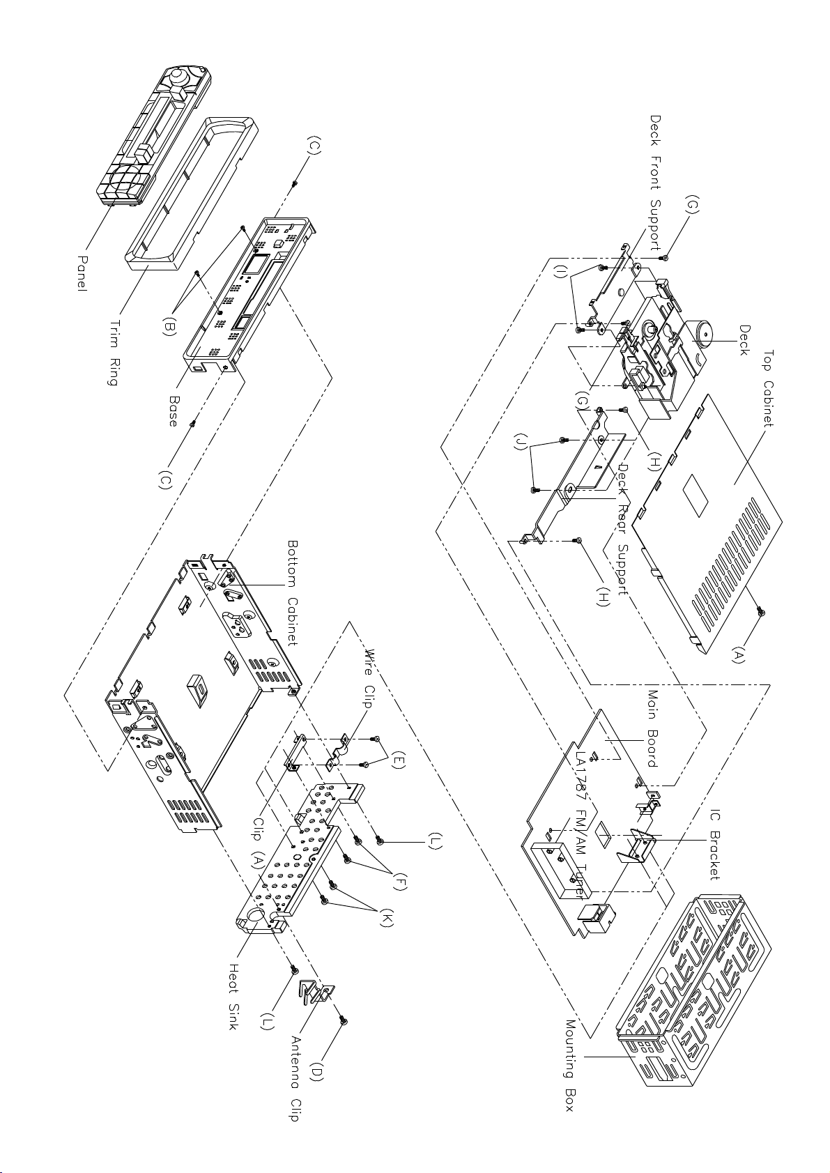
DISASSEMBLY DIAGRAM
4
Page 5
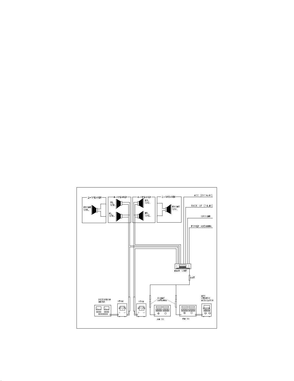
OPERATION CHECK
GENERAL SPECIFICATIONS OF SIGNAL
Standard frequency
Signal output
Modulation
AF output level FM/MW/LW
Power source voltage DC 14.0V (Backup voltage is the same as this)
AF load impedance 4 ohm pure resistance
Balance Center position of level
Tone Center position
The signal strength read in this section is voltage on the antenna.
Test Diagram
FM
MW
LW
FM
MW
LW
MW
FM Stereo
98.1 MHz (87.5, 108 MHz)
1000 kHz (522, 1620 kHz)
200 kHz (144, 288kHz)
1mV
5 mV
5 mV
400 Hz 30% MOD.
1 kHz 75 kHz DEV.
90% for L only or
R only pilot level 10%
5
Page 6
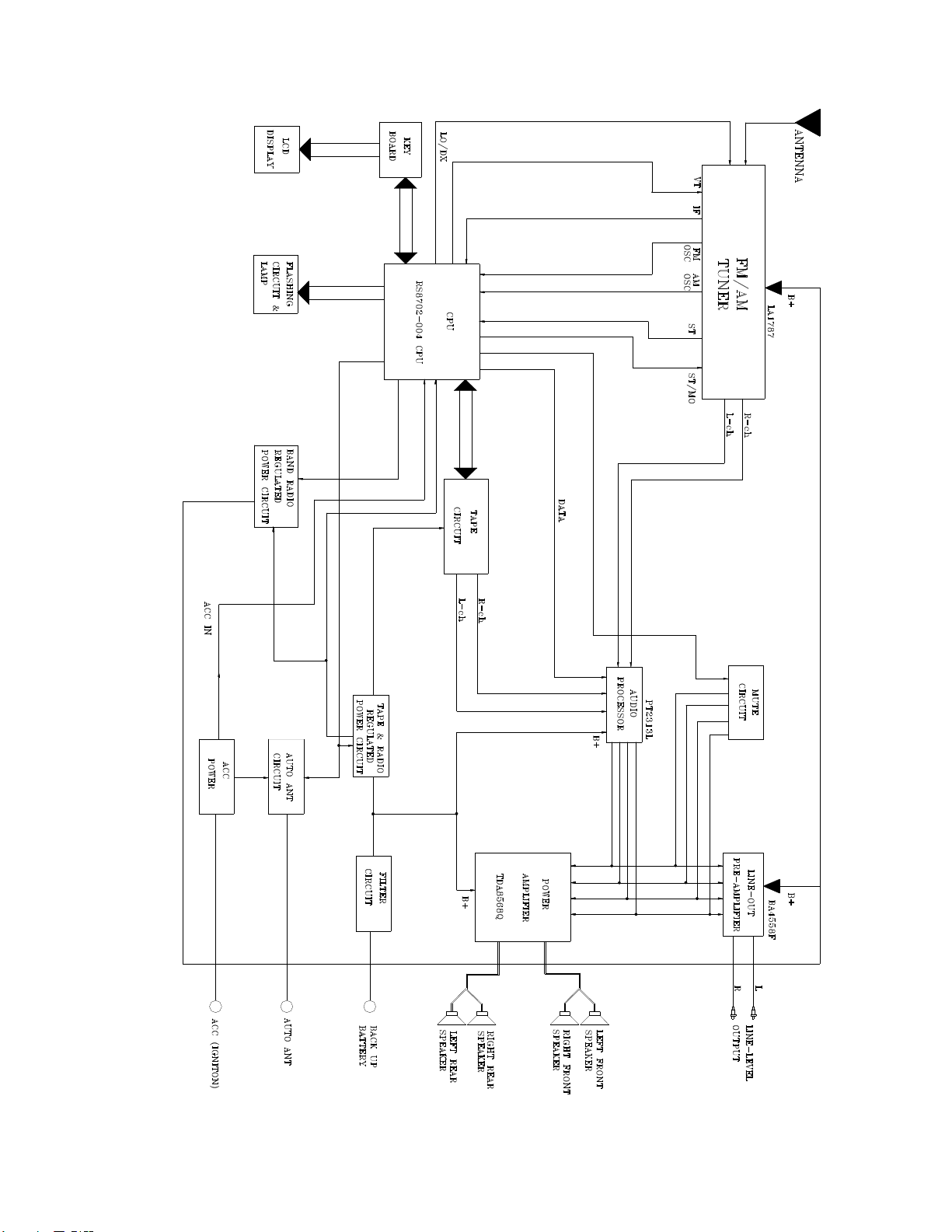
BLOCK DIAGRAM
6
Page 7
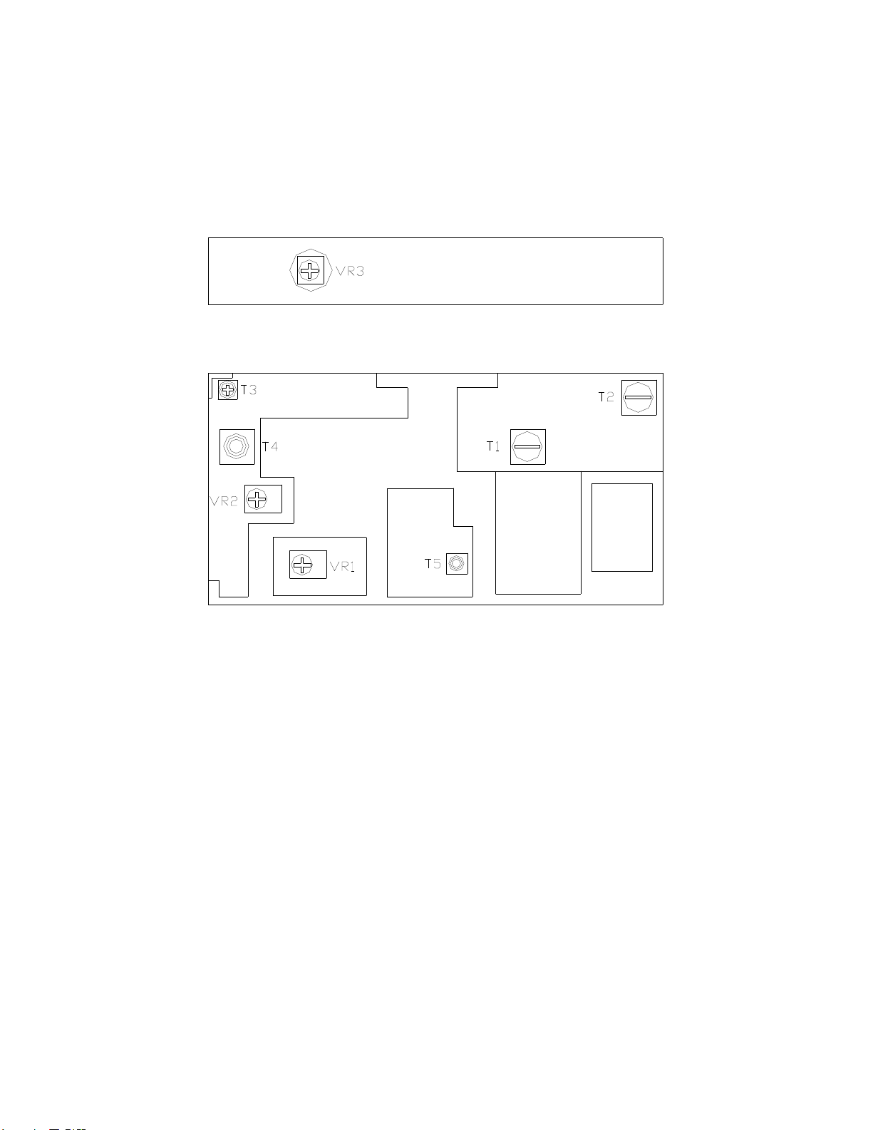
FM/AM TUNER
ALIGNMENT LOCATIONS
7
Page 8

ALIGNMENT PROCEDURES
FM ADJUSTMENT
Equipment Required
l AM IF/RF signal generator
l Solid-state voltmeter (SSVM)
l Regulated DC power supply
l 2-CH voltmeter
l Distortion meter
FM Alignment Using FM Signal Generator
Note: Press the radio power switch to on the radio. Signal generator output must be kept as low as possible
to avoid overload and clipping.
VR1
VR2
Adjustment
VR3
Remarks
Adjust AF
output power
at maximum
separating
more than30 dB
Stereo Separation
25 dB (! 5 dB)
Adjust AF to stop
station.
Step
Stereo
Separation
FM SNC
Adjustment
STOP
SENS.
Note: The tuner module is well-adjust and adjustment is not recommended.
Generator
Coupling
Signal
generator
to antenna
receptacle
98.1 MHz
Dev. 75 kHz
L+R=90 %
Int. 1 kHz
60dB V output
Signal
Generator
To antenna
receptacle
Generator
98.1 MHz
Int. 1 kHz
Dev. 75 kHz
L+R = 90 %
pilot = 10 %
98.1 MHz
@ 40 dBµ
98.1 MHz
mod. 1kHz
dev 75kHz
98.1 MHz
98.1 MHz
98.1 MHz
Display
Setting
8
Page 9

MAIN BOARD
PRINTED CIRCUIT BOARDS
9
Page 10

KEY BOARD
10
TOP VIEW
Page 11

KEY BOARD
BOTTOM VIEW
11
Page 12

WIRING DIAGRAM
12
Page 13

13
Page 14

PANEL
Ref. No.
1
2
3
4
5
6
7
8
9
10
11
12
13
14
15
16
17
18
19
20
21
22
23
24
25
26
27
28
29
30
31
32
33
34
35
36
37
38
39
40
41
42
43
EXPLODED VIEW PARTS LIST
Description
Lens (S. OPC0201)
Top Panel (S. 0201) W/O CDC 143681D
Key Board
Bottom Panel /PC
Open Knob (S.OPC0201)
PROG Spring
EJ Knob (A/R) (S.OPC0201)
EJ Knob Spring
REW Knob
FF Knob
SEL Knob (L-Up) (S.OPC0201)
BND/LOUD Knob (L-Up) (S.OPC0201)
TUNE Knob (L-Up) (S.OPC0201) ENCOD
VOL Knob For Encode (S.OPC0201)
Volume Back Light For SW. Encode
Left Adaptor (A)
Left Adaptor (B)
TUNE Knob Adaptor
MODE Knob (S.OPC0201)
SCAN Knob (L-Up) (S.OPC0201)
MONO Knob (L-Up) (S.OPC0201)
LOC Knob (L-Up) (S.OPC0201)
Hole Cover S. OPC0201
MUTE Knob (L-Up) (S.OPC0201)
Power Knob (L-Up) (S.OPC0201)
1 Knob (L-Up) (S.OPC0201)
2 Knob (L-Up) (S.OPC0201)
3 Knob (L-Up) (S.OPC0201)
4 Knob (L-Up) (S.OPC0201)
5 Knob (L-Up) (S.OPC0201)
6 Knob (L-Up) (S.OPC0201)
DISP Knob (L-Up) (S. OPC0201)
EQ Knob (L-Up) (S. OPC0201)
AMS Knob (L-Up) (S. OPC0201)
Middle Adaptor Spring White
Right Adaptor
LCD POS Dull TRAM. TI9012
White TRANSFLECTOR
LCD Back Light
Left Back Light
Right Back Light
CD115 Rotary Encoder VOL
Screw ∅2X8 BA/ST Black
RS Part No.
Mfr s Part No.
12-14310-305
52-A4341-81B
52-A4354-81B
27-00178-03T
53-A4366-81
51-A4321-82
51-A4324-00
52-A4332-80
36-34254-00
52-A4329-80
36-34501-00
52-A4327-80
52-A4328-80
52-A4340-81
52-A4342-82
52-A4363-00
43-A4303-00
43-A4304-00
43-A4305-00
52-A4361-81
52-A4337-81
52-A4338-81
52-A4339-81
52-A4365-80
52-A4343-81
52-A4344-81
52-A4345-82
52-A4346-82
52-A4347-82
52-A4348-82
52-A4349-82
52-A4350-82
52-A4351-81
52-A4352-81
52-A5353-81
43-A4301-00
43-A4302-00
44-78101-00
52-A4358-01
52-A4360-00
52-A4359-01
18-00115-00
40-12008-21
14
Page 15

CABINET
EXPLODED VIEW
15
Page 16

CABINET
Ref. No.
1
2
3
4
5
6
7
8
9
10
11
12
13
14
15
16
17
18
19
20
21
22
23
24
25
26
27
28
29
30
31
32
33
34
35
36
37
38
39
EXPLODED VIEW PARTS LIST
Description RS Part No.
Panel
Trim Ring +Spray Silver
Base /ABS
Cabinet Bottom
SM909-DL (MCI5ULCKSNZ/AP-4226)
Cabinet Top A/R
Heat Sink W/O Socket; W/O CDC
Main Fiber
Main Board
Mounting Box
Spring Knob
RE Knob Spring
Cass Door OP2320-56
Tape Door Spring
Slide Block
Hook Spring
Hook Support
Socket Board
16PIN Socket
Eject Lever (A/R)
REW/FF Knob Adaptor
Deck Front Support
Deck Rear Support
LA1787 FM/AM Tuner (CET-7000AF)
Touch Sheet
IC Bracket (8568)
BD435 Bracket
Spring Washer M5
Back Mounting Screw
Antenna Clip
Wire Clip
Clip (A)
Screw ∅2 X 4 PH/ST
Screw ∅2 X 6 PA/ST
Screw ∅2.6 X 4 BH/MS
Screw ∅2.6 X 6 BH/MS
Screw ∅2.6 X 12 BH/MS Black
Screw ∅3 X6 PH/MS
Screw ∅3 X 18 PH/MS
Mfr s Part No.
51-64824-81B
51-A4320-00
61-A4302-00
94-00909-01W
61-A4301-00
61-A4306-00
35-A4301-00
12-14301-085
61-02905-00
52-A4323-00
36-11852-00
66-32056-00
36-33004-00
52-A4324-00
36-A4302-00
39-A4305-00
12-14310-305
25-M6368-02
52-A4321-00
52-A4320-00
39-A4301-00
39-A4302-00
29-17870-00
39-A1529-00
39-A4310-00
39-A4308-00
35-50001-00
34-68701-00
39-A4309-00
39-A4306-00
39-A1520-00
40-02004-05
40-02006-10
40-02604-01
40-02606-01
40-12612-11
40-03006-00
40-03018-00
16
Page 17

SCHEMATIC DIAGRAM
17
Page 18

Ref. No. Parts No. Description Q ty
Q503/6
Q307/8,505
Q502,402
Q303~6,401,501,101~6
IC502
D801
D802/3/5,502/1/3,507/8/12/16,806,509
D804
ZD502,301
ZD504~7
ZD503
ZD501
IC301
IC401
IC503
IC802
IC801
IC501
IC101
XT501
C507
C506
C508
C105
C329/30,515/7/8,101/20,122,812
C516
C405/6,109/10
C119
C108
C504/5,315,803,103/16
C311/2
C111/2
C102
C804~7
C303~6
C104
C407/8,115
C314,510,107,123,328
C324~7,403/4,113/4/8
C411/4
C302,310,503,121
C313
C801
ELECTRICAL PARTS LIST
PC BOARD ASSY, MAIN BOARD
01-00435-00S
01-01175-00
01-01240-00
01-02785-00
01-02785-00
02-04001-00A
02-04148-00A
02-05401-00A
02-50051-00A
02-50068-00A
02-50091-00A
02-50100-00A
03-02313-00
03-03161-00
03-07035-00
03-07818-00
03-05868-00
03-08702-004
03-09257-00
04-00045-00
05-00220-06
05-00470-06
05-05102-00A
05-05103-00A
05-05104-00A
05-05104-82
05-05153-00A
05-05220-00A
05-05221-00A
05-05223-00A
05-05272-00A
05-05392-00A
05-05473-00A
05-05682-00A
05-06104-82
05-16225-00
06-10107-01A
06-10476-01
06-16105-01
06-16107-01
06-16225-01
06-16226-01
06-16228-00S
TRANSISTOR BD435
TRANSISTOR 2SA1175-FF
TRANSISTOR B1240
TRANSISTOR 2SC2785-FF
IC-REGULATOR 78L05
DIODE IN4001 AT. (TAPPING)
DIODE 1N-4148 AT. (TAPPING)
DIODE IN5401
ZENER DIODE 5.1V 0.5W AT.
ZENER DIODE 6.8V 0.5W AT.
ZENER DIODE 9.1V 0.5W AT..
ZENER DIODE 10V 0.5W
I.C. PT2313L
I.C. LA-3161
IC KIA7035P
REGULATOR LC-78L18
IC TDA 8568Q/N3 (PWR)
RS8702-004 CPU (CD/MP3 NON RDS)
IC TC9257F
CRYSTAL 4.5MHz HC-18U
CER CAP 22P NPO ±5%
CER CAP 47P NPO 5%
AXIAL CER CAP 1000PF ±20% TP.
AXIAL CER CAP 0.01µF+80/-20% TP.
AXIAL CER CAP 0.1µF+80/-20% TP.
AXIAL TYPE UP050F104Z-NALXXX
AXIAL CER CAP 0.015! F +80/-20% TP.
AXIAL CER CAP 22PF ±5% TP.
AXIAL CER CAP 220PF ±10% TP.
AXIAL CER CAP 0.022! F +80/-20% TP.
AXIAL CER CAP 2700PF ±20% TP.
AXIAL CER CAP 3900PF ±20% TP.
AXIAL CER CAP 0.047! F +80/-20% TP.
AXIAL CER CAP 6800PF ±20% TP.
AXIAL CER CAP 0.1µF X7R ±10% TAPE
TAN CAP 2.2! F 16V
E. CAP 100µF 10V (∅6.3X7 MINI)
E. CAP 47µF 10V (∅4X7 MINI)
E. CAP 1µF 16V (∅4X7 MM)
E. CAP 100µF 16V (∅6.3X7 MM)
E. CAP 2.2µF 16V (∅4X7)
E. CAP 22µF 16V (∅4X7 MM)
E. CAP 2200µF 16V (∅12.5X17 MM)
18
2
3
2
12
1
1
12
1
2
4
1
1
1
1
1
1
1
1
1
1
1
1
1
1
9
1
4
1
1
6
2
2
1
4
4
1
3
5
9
2
4
1
1
Page 19

ELECTRICAL PARTS LIST " CONTINUED
Ref. No.
C514,502
C307/8
C409/10,501,316~9,808
R505
R507,121
R541,125
R415,503,327/9,802/3,107/8
R508,416,556/7,501,101/2/12/15,520
,116
R124,322/3,403/4
R517/22/23,324/5
R509
R320~3
R328
R540
R555,106
R513/31/33/35/37,112/3,316~9
R337
R510/2
R401/2,109
R104,326
R407/8,119/20
R519
R115
R521/28~30,543~6,504,103
R502,801,511/4/8,526/7,532/4/6,414
,114,336
R330
R304/5
R311,409
R547,506
R405/6
L501/2,101
L801
FM TUNER 29-17870-00 LA17878 FM/AM TUNER (CET-7000AF) 1
Q201/2
C201
C202
C203
C205
C204
PC BOARD ASSY, FM TUNER BOARD
PC BOARD ASSY, AM TUNER BOARD
Parts No.
06-16476-01
06-50334-01
06-50475-01
07-05010-00
07-05100-16A
07-05101-16A
07-05102-16A
07-05103-16A
07-05104-16A
07-05105-16A
07-05123-16A
07-05152-16A
07-05153-16A
07-05182-16A
07-05221-16A
07-05222-16A
07-05223-16A
07-05224-16A
07-05330-16A
07-05331-16A
07-05332-16A
07-05334-16A
07-05471-16A
07-05472-16A
07-05473-16A
07-05561-16A
07-05562-16A
07-05680-16A
07-05681-16A
07-05752-16A
09-70100-01
12-14301-085
15-27014-01
01-01175-00
05-05102-00A
05-05103-00A
05-05104-00A
05-05223-00A
06-10107-01
E. CAP 47µF 16V (∅5X7MM)
E. CAP 0.33µF 50V (∅4X7MM)
E. CAP 4.7µF 50 (∅4X7 MINI)
RES. 1Ω 1/4W
RES. 10Ω 1/16W (TAPPING)
RES. 100Ω 1/16W (TAPPING)
RES. 1KΩ 1/16W (TAPPING)
RES. 10KΩ 1/16W (TAPPING)
RES. 100KΩ 1/16W (TAPPING)
RES. 1M" 1/16W (TAPPING)
RES. 12KΩ 1/16W (TAPPING)
RES. 1.5KΩ 1/16W (TAPPING)
RES. 15KΩ 1/16W (TAPPING)
RES. 1.8KΩ 1/16W (TAPPING)
RES. 220Ω 1/16W (TAPPING)
RES. 2.2KΩ 1/16W (TAPPING)
RES. 22KΩ 1/16W (TAPPING)
RES. 220KΩ 1/16W (TAPPING)
RES. 33Ω 1/16W (TAPPING)
RES. 330Ω 1/16W (TAPPING)
RES. 3.3KΩ 1/16W (TAPPING)
RES. 330KΩ 1/16W (TAPPING)
RES. 470Ω 1/16W (TAPPING)
RES. 4.7KΩ 1/16W (TAPPING)
RES. 47K" 1/16W (TAPPING)
RES. 560Ω 1/16W (TAPPING)
RES. 5.6KΩ 1/16W (TAPPING)
RES. 68Ω 1/16W (TAPPING)
RES. 680Ω 1/16W (TAPPING)
RES. 7.5KΩ 1/16W (TAPPING)
MICRO INDUCTOR 10UH AXIAL TYPE
PCB C14368X3.6 YMB 1.6X168X147
RING COIL # 27X14MM V-TYPE
TRANSISTOR 2SA1175-FF
AXIAL CER CAP 1000PF 20% TP
AXIAL CER CAP 0.01! F +80/-20% TP.
AXIAL CER CAP 0.1! F +80/-20% TP.
AXIAL CER CAP 0.022! F +80/-20% TP.
E. CAP 100! F 10V (# 5X7MM MINI)
Description
Q ty
2
2
8
1
2
2
9
11
5
5
1
4
1
1
2
11
1
2
3
2
4
1
1
10
13
1
2
2
2
2
3
1
1
2
1
1
1
1
1
19
Page 20

R202
R204/5
R123
R206/7
R201
R208
LED
IC601
C601
C602
R608
R620
R610
R627/8
R603,612
R604/13
R621/18
R611
R605/14
R622
R617
R606/15
R601
R602
R607/16/19
R609
SW
AMS
RST
C401/2
R417
R332/3
RCA OUT
LED
RST
ELECTRICAL PARTS LIST " CONTINUED
Ref. NO Part No. Description Q ty
07-05100-16A
07-05102-16A
07-05103-16A
07-05223-16A
07-05331-16A
07-05332-16A
PC BOARD ASSY, KEY BOARD
02-30000-02D
03-75823-00
05-03223-10
05-03681-00
07-05122-54
07-05152-54
07-05153-54
07-05181-00
07-05181-54
07-05221-54
07-05222-54
07-63331-00
07-05331-54
07-05332-54
07-05393-54
07-05471-54
07-05472-54
07-05513-54
07-05681-54
07-05682-54
12-14310-305
16-01107-00K
16-01140-04
16-05001-00
PCBOARDASSY, SERVO BOARD
05-02152-10
07-05473-16A
PC BOARD ASSY, LINE OUT BOARD
07-05102-16A
20-20200-08
PC BOARD ASSY, FRONT BOARD
02-30000-02D
16-05001-00
RES. 10Ω 1/16W (TAPPING)
RES. 1KΩ 1/16W (TAPPING)
RES. 10KΩ 1/16W (TAPPING)
RES. 22KΩ 1/16W (TAPPING)
RES. 330Ω 1/16W (TAPPING)
RES. 3.3KΩ 1/16W (TAPPING)
LED # 3MM RED
IC LC75823ED
CHIP CAP CM21X7R223K25AT
CHIP CER 680P 50V X7R TA
CHIP RES 1.2KΩ 1/10W
CHIP RES 1.5KΩ 1/10W
CHIP RES 15KΩ 1/10W
RES 180Ω 1/4W
CHIP RES 180Ω 1/10W
CHIP RES 220Ω 1/10W
CHIP RES 2.2KΩ 1/10W
CHIP RES 2.7KΩ 1/10W
CHIP RES 330" 1/10W
CHIP RES 3.3KΩ 1/10W
CHIP RES 39KΩ 1/10W
CHIP RES 470" 1/10W
CHIP RES 4.7KΩ 0805 1/10W 5%
CHIP RES 51KΩ 1/10W
CHIP RES 680Ω 1/10W
CHIP RES 6.8KΩ 1/10W
RDS143681 KB D/S 1.2X167.6X42.3
TACT SW. DCT/1101 4.3MM 2 PIN
TACT SW. KPS-1107SW H=2.5 KIE
TACT SW. TS-065001-150 H=5MM
MYLAR CAP 0.0015! F 10%
RES. 47K" 1/16W (TAPPING)
RES. 1kΩ 1/16W (TAPPING)
DOUBLE RCA CABLE 200MM Grey
LED # 3MM RED
TACT SW TS-065001-150 H=5MM
1
2
1
2
1
1
1
1
1
1
1
1
1
2
2
2
2
1
2
1
1
2
1
1
3
1
1
18
1
1
2
1
2
1
1
1
20
Page 21

pmb`fcf`^qflkp=
=
T. H. D .................................................................................................................................... Less than 0.35%
Signal to Noise Radio..............................................................................................................More than 60 dB
Channel Separation.................................................................................................................More than 60 dB
Frequency Response ............................................................................................................... 50Hz - 8,000Hz
Stereo separating (FM) ............................................................................................................ 30 dB (at 1kHz)
Signal to noise ratio (FM) ...................................................................................................... Better than 45 dB
Output power ..................................................................................................................................... 4 X 25W
Speaker output impedance .............................................................................................................4 To 8 ohm
Power source.......................................................................................... DC 12V (11~16V) Negative ground.
Frequency range ............................................................................................................ FM 87.5 - 108.0 MHz
............................................................................................................................................. MW 522-1620 kHz
.............................................................................................................................................. LW 144 - 288 kHz
Sensitivity .......................................................................................................................FM 3 V (S/N=30 dB)
..................................................................................................................................... MW 32 dB (S/N=20 dB)
...................................................................................................................................... LW 35 dB (S/N=20 dB)
Specifications are subject to change without notice.
21
 Loading...