

AKAI

DIGITAL INTEGRATED AMPLIFIER
AM-M939
Operator's Manual 5
| English | Page | 1~17 | ||||||||
|---|---|---|---|---|---|---|---|---|---|---|
| Français | Page | 19~35 | ||||||||
| Deutsch | Seite | 37~53 | ||||||||
| Nederlands | Pagina | 55~71 | ||||||||
| Español | Página | 73~89 |
1083
WARNING
This is the Akai Digital Integrated Amplifier
Use the Akai amplifier in combination with the other components in the Akai Midi-series and you will have an excellent hi-fi system.
To prevent fire or shock hazard, do not expose this appliance to rain or moisture.
Features
1
- Dual pole DC servo power amplifier with open loop circuit
- Optical and coaxial digital interface connection system for CD player and DAT deck (Page 3, 13)
- 2 times over sampling digital filter incorporating D/A converter for compact disc and DAT cassette playback
- Microcomputer controlled function controls
- Motor driven volume control
- DIRECT OPERATION switch (Page 7, 14)
- REC MODE SELECTOR switch (Page 10, 11)
- Super bass, bass and treble tone controls (Page 14)
- 2-sets of speaker connections (Page 7, 15)
- Exclusive processor input and output jacks and graphic equalizer recording jacks (Page 12) Electronic speaker protection system with
- Electronic speaker protection system with muting circuit (Page 15)
- Loudness switch and subsonic switch (Page 14)
- Remote control function (Page 4)
Table of contents
| Warning 1 |
|---|
| What you should know to protect yourself 2 |
| Before using the Akai amplifier 3 |
| Placement 3 |
| On the Akai CD player connection 3 |
| On the wireless remote control unit 4 |
| Making the right connections |
| Controls |
| Let's enjoy music |
| Let's record 10 |
| Tape dubbing 11 |
| Expanding Your Hi-Fi system 12-13 |
| Graphic equalizer and turntable connections. 12 |
| DAT deck connections |
| Operation details 14-15 |
| Protection circuit |
| The speaker system 15 |
| Problem? Let's check |
| Specifications |
Lithium battery
This product uses a lithium battery for memory back-up. The lithium battery should only be replaced by qualified service personnel. Improper handling may cause risk of explosion.
Power requirements
Power requirements for electrical equipment differ from area to area.
Please ensure that your machine meets the power requirements in your area.
If in doubt, consult a qualified electrician.
220 V, 50 Hz for Europe except UK
240 V, 50 Hz for UK and Australia
What you should know to protect yourself
Watch out! You might get an electric shock
- Never touch the plug with wet hands.
- Always pull out by the plug and never the cord.
- Only let a qualified professional repair or reassemble the Akai Amplifier. An unauthorized person might touch the internal parts and receive a serious electric shock.
- Never allow a child to put anything, especially metal, into the Akai Amplifier.
Let's protect the Akai Amplifier too.
- Use only a household AC power source. Never use a DC power source.
- Make sure that the power consumption of each component does not exceed the wattage specified on the rear panel.
- If water is spilled on the Akai Amplifier, disconnect it and call your dealer.
- Make sure that the Akai Amplifier is well ventilated and away from direct sunlight. Be careful not to block the side ventilator of the Akai Amplifier.
- To avoid damages to the internal circuits and the external surface, keep away from heat (stoves, etc.)
- Avoid using spray type insecticide near the Akai Amplifier. It can damage the finish and might ignite suddenly.
- To avoid damaging the finish, never use alcohol, paint thinner or other similar chemicals to clean the Akai Amplifier.
- Place the Akai Amplifier on a flat and solid surface.
- If you don't plan to use the Akai Amplifier for a long period of time, disconnect the power cord.
To enjoy the Akai Amplifier for a long time, please read this operator's manual thoroughly.
3 Before using the Akai Amplifier
Placement
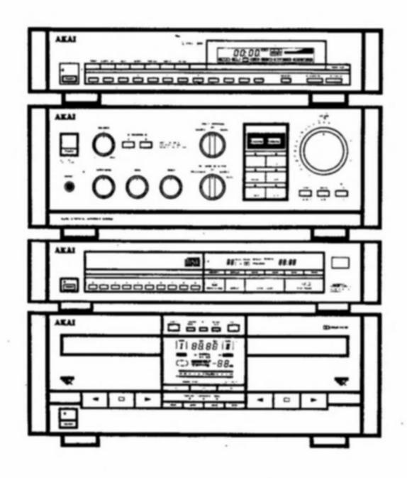
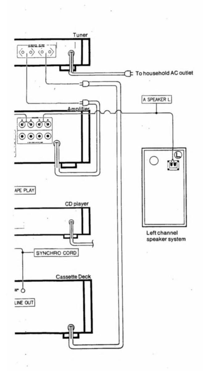
Stack the Akai Midi series components as shown in the illustration.
If you wish to change this order, always make sure that there is another component separating the amplifier and cassette deck. The tuner and CD player should also have another component between them.
When installing the components
Use an audio rack which has heat radiation holes.
Interference
This amplifier has a D/A converter for CD and DAT cassette playback. If there is any interference during TV reception, turn OFF the power switch of the amplifier if you are not using it.
Notes for connection and optical terminals
- Connect the plug firmly, with it's printed face up.
- When connecting and disconnecting the cable, pull by the plug not the cable.
- Keep the plug and inside of the terminals clean. Do not scratch the top of the cable.
- Replace the terminal caps when the terminals are not in use.
- Do not bend the cable.
- If you are winding the cable, loops with a 15 cm diameter or more are recommended.
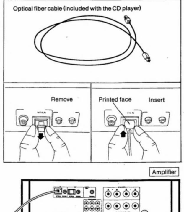
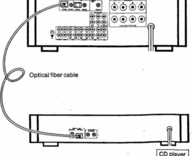
On the Akai CD player connection
Use the optical fiber cable provided with the CD player for connections
Before connecting
- Turn off all the components.
- Remove the terminal caps from the CD OPTICAL terminal of the Akai amplifier and the DIGITAL OUT OPTICAL terminal of the Akai CD player.
- Do not loose these terminal caps. The terminal caps will protect these optical terminals from dust.
- Do not make connections to OPTICAL terminals, COAXIAL jacks and the CD (L/R) PIN-jacks at the same time. This will result in the OPTICAL and COAXIAL input signals being cut automatically.
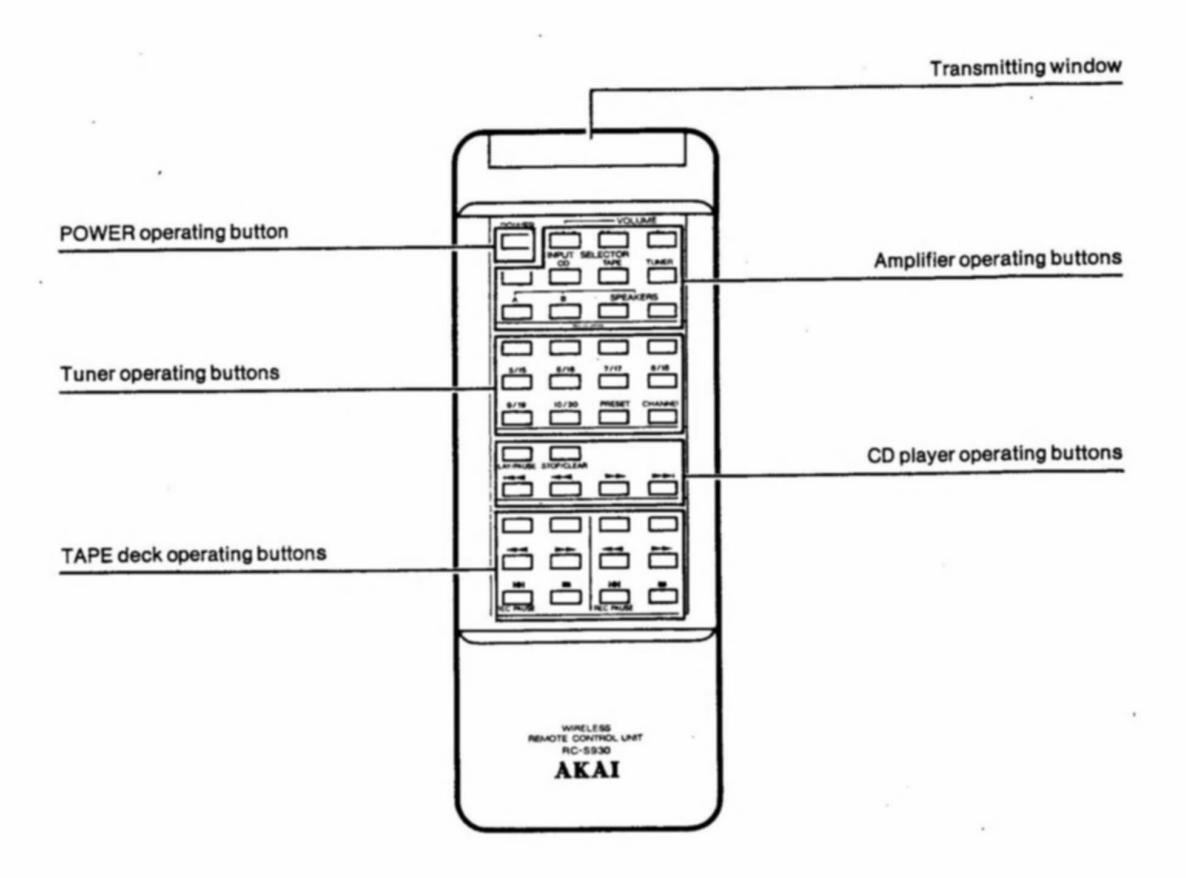
On the wireless remote control unit
The wireless remote control unit can be used to control all the operations on the following Akai Midi series components:
AT-M739/L Tuner, AM-M939 Amplifier, CD-M939 CD player and GX-M959W Cassette deck.
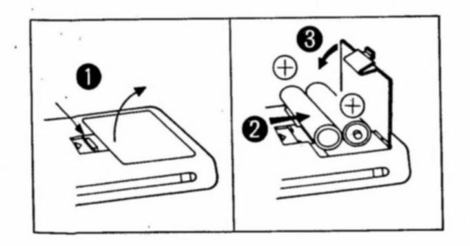
Loading the batteries
• Push the release lever while pulling the battery compartment cover to open.
Insert two 1.5 V (R6, AA SUM-3 or equivalent size) dry batteries, according to the polarity guides.
Replace the cover.
Notes on the remote control operation and batteries
- Please read the information printed on the dry batteries.
- Do not use the remote control unit near fluorescent lamps which may shorten the operation range of the remote control unit.
- As the strength of the remote control unit's batteries become depleted, the operation range of the remote control will become shorter. In this case, the batteries should be replaced with new ones.
- If you aren't planning to use the remote control unit for a long period of time, take the batteries out.
- When replacing the batteries, always clean all the terminals with a dry cloth and replace both batteries at the same time.
- Do not use any batteries other than those recommended.
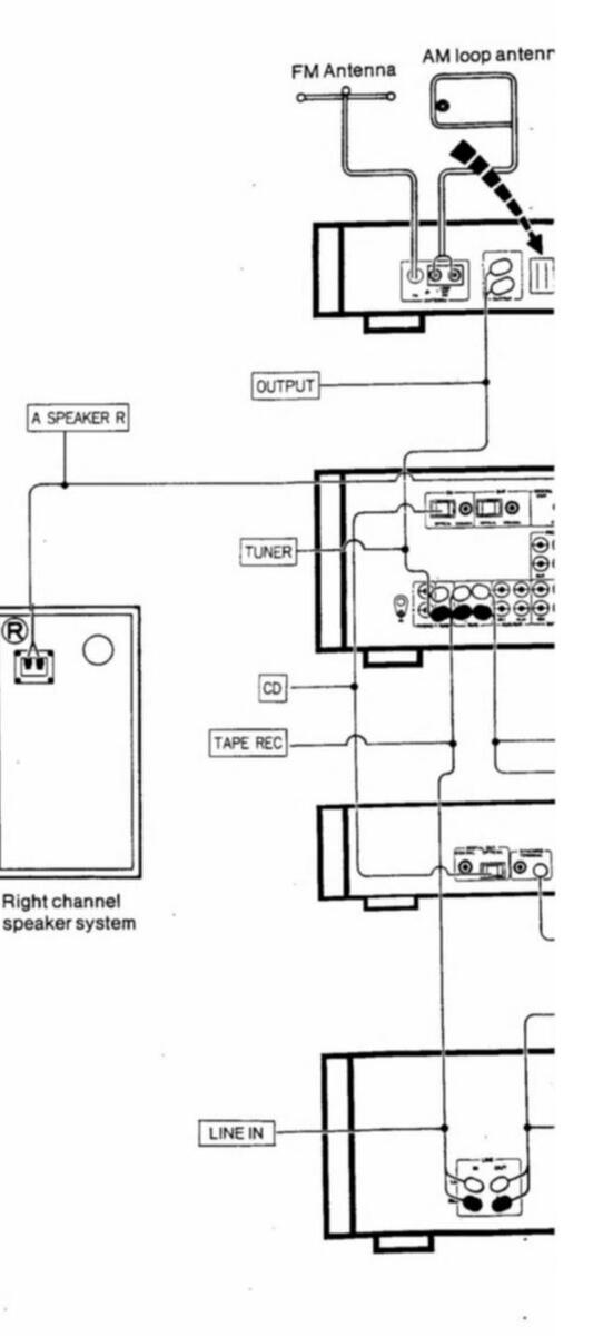
Making the right connections
Before connecting
5
- Turn off all the components before connecting.
- Connect the power cord last.
- Make sure that you connect the white PIN-plug to the left (white) jack and the red PIN-plug to the right (red) jack.
- Connect everything securely. Loose connections can lead to distortion.
- To prevent damage to the cords, connect and disconnect by holding the plug and not the cord.
- Make sure that the power cords and the connection cords do not get tangled with each other. This can lead to distortion.
- If your turntable has a ground wire, connect it to the Akai amplifier's ground terminal (7/7) securely.
AUX/DAT REC and PLAY jacks
These are auxiliary jacks. Connect such components as a 2nd DAT deck or cassette deck to these jacks.
CD and DAT PIN-jacks
Connect the CD player and the DAT deck to these jacks with the conventional PIN-plug cords. When these jacks are being used, the CD and DAT OPTI-CAL terminals and COAXIAL jacks are cut automatically.
For digital interface connection use the OPTI-CAL terminals or COAXIAL jacks.
PHONO and PROCESSOR jacks
Connect the Akai turntable to the PHONO jacks of the Akai amplifier.
Connect the Akai graphic equalizer or surround processor to the PROCESSOR jacks of the Akai amplifier.
Refer to the operator's manual of the turntable and the graphic equalizer, etc..
Ground terminals
If your turntable has a ground wire, connect it to this terminal securely.
SPEAKERS terminals
Be sure to connect the:
- + wires to the + terminals (red);
- wires to the terminals (black);
Left speaker to the Left (L) terminals: and Right speaker to the Right (R) terminals.
How to connect the speakers
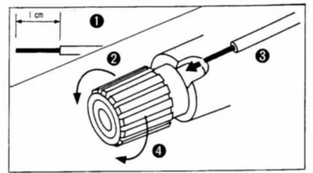
Strip off a 1cm length of vinyl covering from the end of the speaker cord.
- Loosen the Red and Black speaker terminals by turning them counter-clockwise. (These terminals cannot be removed.)
- Twist the speaker wires firmly, then insert them through the opening of the speaker terminals guards.

Turn the terminals clockwise to securely fasten the cords.
IMPORTANT: Do not cross connect speaker systems. Use either the A terminals or B terminals for a pair of speakers. Do not connect one speaker to an A terminal and the other to a B terminal.
On the required speaker impedance
When using one pair of speakers:
Turn one of the A or B SPEAKERS switches to on. Connect speakers of 6 to 16 ohms impedance.
When using two pairs of speakers:
Turn both the A and B SPEAKERS switches to on. Connect speakers of 12 to 16 ohms impedance.
Refer to the markings on the amplifier's rear panel.
Power cord
Connect this cord to the Akai tuner's SWITCHED AC OUTLET or directly to a household AC outlet.
On the PROCESSOR IN/OUT and G.E. REC jacks This Akai amplifier is equipped with special PROC-ESSOR jacks for connection to a graphic equalizer or audio processor.
Remove the pins of these jacks only when connecting one of these accessories and keep them in a safe place. Do not lose these pins. Refer to page 12.
DIGITAL OUT COAXIAL jack
Connect the DAT deck's DIGITAL INPUT jacks or a D/A converter which has a digital interface circuit. Connection can be made with a coaxial PIN-plug cord such as a video connection cable available in most Hi-Fi stores. Refer to page 13.
Important!
The illustrated power plugs are intended for general reference. The power plug used in your country may differ from the illustration. (Example: U.K., Australia, U.S.A., Europe etc.)
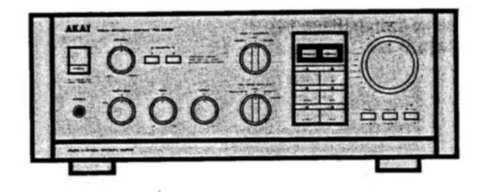
7 Controls
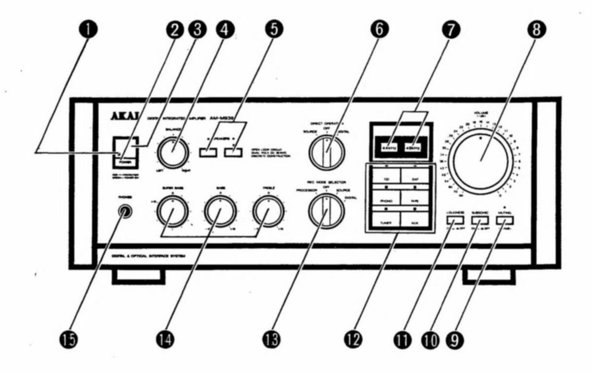

POWER Indicator
Indicates the power is turned on. Also indicates the speaker protection circuit operation. When the speaker protection system is engaged, the indicator will be red.
POWER Switch
To turn the Akai amplifier on and off.
6
Remote control receiver For remote control operation.
BALANCE Control To adjust the left and right channel balance.
5 A/B SPEAKERS Switches and Indicators To select the speaker system.
6 DIRECT OPERATION Switch To select the playback operation mode of the Akai amplifier.
SAMPLING FREQUENCY Displays (44 kHz/48 kHz)
Shows which digital input signal has been selected when using the digital interface connections.
44 kHz: CD player's signal is selected. 48 kHz: DAT deck's signal is selected.
- VOLUME (-dB: minus decibel) Control To adjust the volume level. The 0 dB (zero decibel) position is the maximum volume of the amplifier.
-
MUTING Switch and Indicator To reduce volume instantly during playback without using the VOLUME control.
- SUBSONIC Switch (ON /OFF ) To turn the subsonic filter on and off.
LOUDNESS Switch (ON - /OFF - ) For instant compensation of tone setting at low volume.
-
To select the playback source you want to listen to.
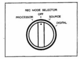
- REC MODE SELECTOR Switch (PROCES-SOR/OFF/SOURCE/DIGITAL)
- For recording operation.
BLE) To adjust the super bass note (super bass), bass note (bass) and high note (treble) levels.
Headphones (PHONES) jack For headphone listening.
Let's Enjoy Music
Set the following controls before turning on the power of your amplifier
| ٠ | VOLUME control | Minimum (−∞) |
|---|---|---|
| BALANCE control | Center | |
| REC MODE SELECTOR | ||
| switch | OFF | |
| LOUDNESS switch | OFF (=) | |
| SUBSONIC switch | OFF ( = ) | |
| Tone controls | All controls to 0 |
Basic Operation for digital source playback
Use the optical or coaxial cables to connect the CD player or the DAT cassette deck to the Akai amplifier.
For compact disc and DAT cassette playback

Select the speaker system for playback with the A and B SPEAKERS switches.
Press the appropriate button according to how the speaker system is connected.
Set the DIRECT OPERATION switch to DIGI-TAL.
Press the CD or the DAT button, depending on which source you want to listen to, as follows:
Press the CD button for compact disc playback.
The 44 kHz display will light.
2
A
Press the DAT button for DAT cassette playback.
The 48 kHz display will light.
Playback a compact disc.
Adjust the VOLUME control to suit your taste.
Note
When the DIRECT OPERATION switch is set to DIGITAL, the tone controls and balance control are ineffective.
Basic Operation for digital source playback
Ð
Depress the POWER switch to turn on the power.

Select the speaker system for playback with the A and B SPEAKERS switches. Press the appropriate button according to how the speaker system is connected.
Set the DIRECT OPERATION switch to SOURCE.
Press the input select button of the source you want to listen to as follows: For compact disc playback Press the CD button. For DAT cassette playback Press the DAT button. For record playback
For record playback Press the PHONO button. For cassette playback Press the TAPE button.
For radio listening Press the TUNER button. For auxiliary source playback
Press the AUX button.
Playback a compact disc.
Adjust the VOLUME control to suit your taste.
Notes
- When the DIRECT OPERATION switch is set to SOURCE, the tone controls and balance control are ineffective.
- When using the optional graphic equalizer, set the DIRECT OPERATION switch to OFF.
Let's Record
Normal recording operation
Use the REC MODE SELECTOR switch and the input select buttons for recording operations. Normally set to OFF when not recording.
Before recording
Turn on all the components.
If you want to make a copy directly from an original cassette:
Use the dubbing function of the Akai double cassette deck.
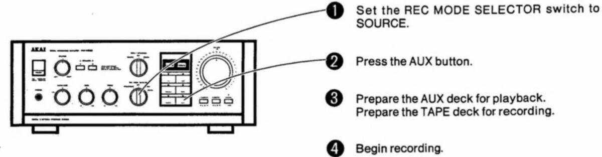
Set the REC MODE SELECTOR switch to SOURCE.
Select the recording source with the proper input select button.
a compact disc a DAT cassette a record the radio a compact disc Press the CD button. Press the DAT button. Press the PHONO button. Press the TUNER button.
an auxiliary source
Play back the source.
Prepare the tape deck for recording, then begin recording.
Press the AUX button.
Digital recording operation
This operation uses the digital interface circuit.
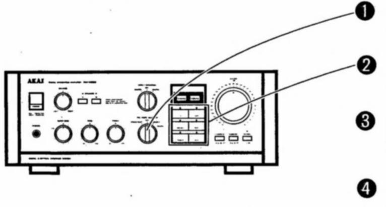
Set the REC MODE SELECTOR switch to DIGITAL.
Press the CD button to record from a compact disc to a DAT cassette.
Play back the compact disc.
Prepare the DAT deck for recording, then begin recording.
Notes for recording operation.
- If you want to adjust the tone controls and balance control, set the DIRECT OPERATION switch to OFF before recording. Recorded signals will not be affected by these adjustments.
- Do not touch the input select button or REC MODE SELECTOR switch during recording. This will interfere with the recording operation.
- When the REC MODE SELECTOR switch is set to DIGITAL, the cassette deck will not record.
10
11 Tape Dubbing
Copving a prerecorded cassette tape:
Connect a 2nd cassette deck using the AUX/DAT jacks of the Akai amplifier. If your cassette deck has a dubbing feature, you can use it for easy operation.
Using the graphic equalizer recording feature
Prepare the AUX deck for playback. Prepare the TAPE deck for recording.
Set the REC MODE SELECTOR switch to PROCESSOR
Select the source you want to record with the proper input select button.
Playback a source and adjust the frequency level controls of the connected graphic equalizer.
Prepare the deck for recording, then begin recording.
Notes for the recording operation
- If you want to adjust the tone controls and balance control, set the DIRECT OPERATION switch to OFF before recording. Recorded signals will not be affected by these adjustments.
- Do not touch the input select button or REC MODE SELECTOR switch of the Akai amplifier and the level controls of the connected graphic equalizer during recording. This will interfere with the recording operation.
- Refer to page 12 for the graphic equalizer connection.
Expanding Your Hi-Fi System
Graphic equalizer and turntable connections
Take advantage of the full potential of your Akai amplifier and increase your listening pleasure by adding a turntable or, for more finely adjusted tone compensation, a separate graphic equalizer or audio processor.
Placement
- Place the Akai turntable on the Akai tuner's top panel.
- Place the optional Akai graphic equalizer or audio processor between the Akai tuner and the Akai amplifier.
Before connecting
- Turn off all the components.
- Refer to the operator's manual of your graphic equalizer or audio processor for further details.
Remove the two short pins from the amplifier's PROCESSOR IN and OUT jacks.
Do not loose these pins. Replace them when an audio processor or a graphic equalizer is not connected to the Akai amplifier.
If you want to record with the graphic equalizer
Connect the G.E. REC IN jacks of the Akai amplifier and the TAPE 1 REC jacks of the Akai graphic equalizer. (Connection-A)
If your turntable has a ground wire
Connect it to the ground terminals (7/7) of the Akai amplifier.
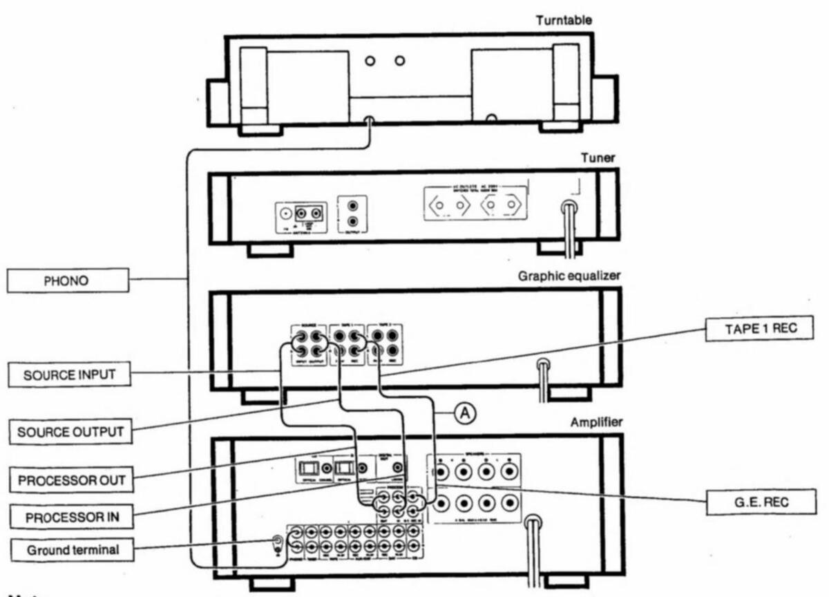
Note
Illustrations indicate additional connections only.
DAT deck connections
If your DAT deck has an optical or coaxial type digital interface connection system, you can connect the Akai amplifier to the DAT OPTICAL terminal or the COAXIAL jack directly.
Notes for terminals and connections
- Insert the plug in the terminal with it's printed side up.
- When connecting and disconnecting the cable hold it by the plug, not the cable.
- Keep the terminals and plugs clean. Do not scratch the top of the plugs.
- Replace the terminal caps when the terminals are not in use.
- Do not bend the cable. Avoid acute angles when making connections.
Playback with the digital interface (OPTICAL terminal or COAXIAL jack) and recording from the DAT REC PIN jacks
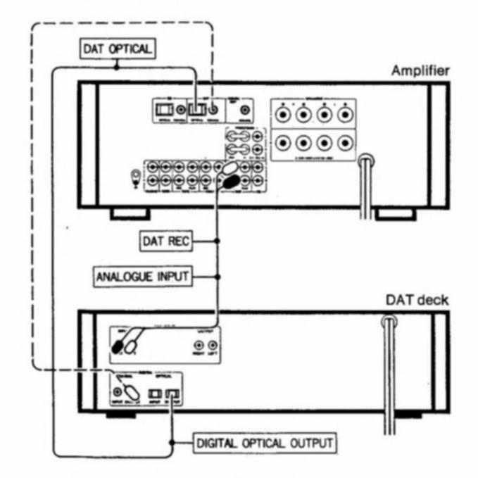
If you have a 2nd cassette deck
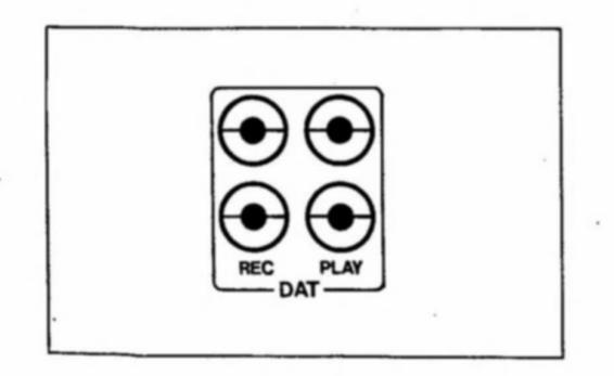
Use the DAT REC/PLAY jacks for connections. Connect the DAT REC jacks of the Akai amplifier to the LINE IN jacks of your cassette deck. Connect the DAT PLAY jacks of the Akai amplifier
to the LINE OUT jacks of your cassette deck.
Connect the AUX/DAT REC/PLAY jacks in the same manner.
Notes
- The DAT OPTICAL terminals and the COAXIAL jack will be cut automatically when the DAT PLAY PIN jacks are being used.
- Dotted lines indicate the coaxial cable when used for connection.
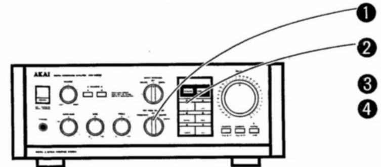
Operation details
For the best sound reproduction of all sources
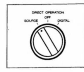
Set the DIRECT OPERA-TION switch to SOURCE or DIGITAL during CD or DAT cassette playback.
Note
When the DIRECT OPERATION switch is set to SOURCE or DIGITAL, the BALANCE control and tone controls are ineffective.
If you want to reduce the volume instantly during playback
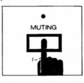
Press the MUTING button to ON. The indicator will light.
To resume the normal listening volume level Press the MUTING button once again to OFF. The indicator will go off.
To adjust tone during playback
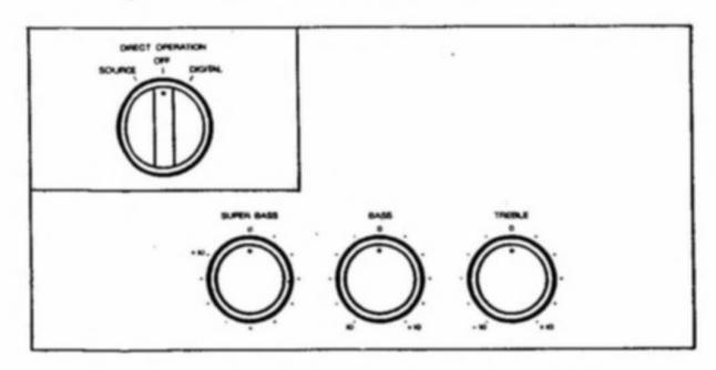
- 1 Make sure to set the DIRECT OPERATION switch to OFF.
- 2 Use the SUPER BASS, BASS and TREBLE tone controls.
To increase the super bass note
.... Use the SUPER BASS control.
To increase or decrease the bass note .... Use the BASS control.
To increase or decrease the treble note .... Use the TREBLE control.
When listening to music at low volume levels
Depress the LOUDNESS button to ON ( - ). When listening to music at normal or high volume levels, set the LOUDNESS switch to OFF ( - ).
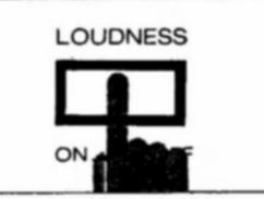
Loudness compensation
The human ear is less sensitive to low and high frequencies at low volume levels. If these frequencies are not boosted or compensated, the sound will seem unnatural. A more natural sound can be obtained by boosting the bass and treble responses. This is called loudness compensation.
On the Balance control
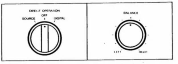
- 1 Make sure to set the DIRECT OPERATION switch to OFF.
- 2 Use the BALANCE control when you feel that there is a deficiency in the left and right balance due to the speaker placement.
It is best to use a monaural source to test the balance. After setting the volume, tune in an AM station and move the BALANCE control to the left or right to boost the volume in the left or right channel respectively.
If the woofer cone vibrates during record playback
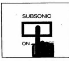
Set the SUBSONIC switch to ON (-). For other source playback except record playback: Set the SUBSONIC switch to OFF (-).
On the subsonic filter
The subsonic filter will eliminate the ultra low frequency noise (below 15 Hz to 20 Hz) during record playback. Whatever this amplifier interprets as a playback signal will be reproduced. Sometimes this will include unwanted noise such as subsonic noise during record playback. The subsonic filter will eliminate this.
15
Headphone use and SPEAKERS switches
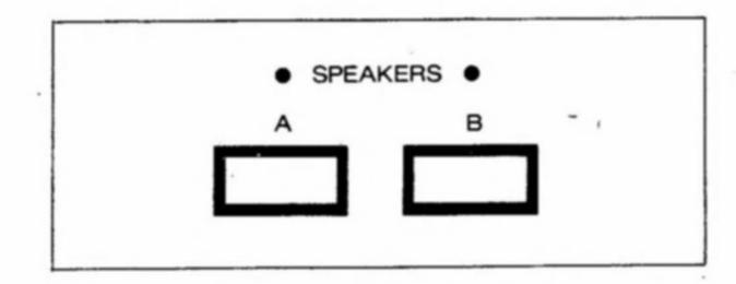
The SPEAKERS A and B switches allow you to switch between the speakers connected to the A SPEAKERS terminals or the B SPEAKERS terminals on the rear panel of the Akai amplifier.
If only one set of speakers is connected to the rear SPEAKERS terminals, simply set the other switch to OFF. When listening through headphones, set both speaker switches to OFF.
Protection circuit
When the Akai amplifier is turned on, no signal will be output to the speakers for a few seconds. The power indicator will first light up red for a few seconds, then change to green when the Akai amplifier has gone into normal operation mode.
This is due to the protection circuit which prevents output of noise when the Akai amplifier is turned on.
The protection circuit also functions during playback to protect the speakers from overloading, and to protect the circuit from damages. When speakers with less than rated impedance are used, the protection circuit will short-circuit the + and -, speaker cords.
When the protection circuit is engaged, the POWER indicator will change from green to red and output signals will be cut automatically.
Should the sound be cut during playback and the power indicator changes from green to red:
- 1 Turn off the Akai amplifier.
- 2 Check for and correct the cause.
- 3 Turn on the Akai amplifier.
The speaker system
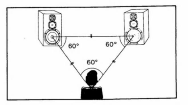
Speaker placement
The playback characteristics of the speaker system(s) are greatly influenced by the placement and the room in which the speakers are used. For example, if the speaker system is placed near a hard wall, the bass will sound better but the treble might seem too strong. Play back some music without using the tone controls and move the speaker system around to find the best location. However, please keep the following in mind.
Place the speaker system:
- On a flat and solid surface which does not transmit too many vibrations.
- In a well ventilated, not very humid place.
- Away from direct sunlight and heat sources (stoves, etc.).
- Away from your turntable and TV.
To prevent damage to the speaker system:
- Do not raise the volume too high.
- Turn off the Akai amplifier when changing or connecting the player system's cartridge.
- Lower the volume when changing radio stations and when cueing or reviewing tapes.
- Do not touch the speakers' diaphragms.
How to clean the speaker system(s):
- Clean the speaker system(s) with a soft, dry cloth.
- If it is very dirty, use a mild detergent.
- To protect the diaphragms (the vibrating parts), do not spray liquid cleaner directly on the speaker system. Always spray it on a cloth first.
- Never use alcohol, paint thinner or use a spraytype insecticide near the speaker system, as this will damage the finish.
Problem? Let's check
No sound
- Check to see if the power cord is connected securely to the household AC outlet.
- The input select button corresponding to the music source you want to listen to is engaged.
- Press the appropriate input select button. The VOLUME control is set too low.
- Adjust the VOLUME control.
- The SPEAKERS switch is turned OFF. Turn ON the A and/or B SPEAKERS switch. The DIRECT OPERATION switch is not set
- properly.
- Set the switch to appropriate position. MUTING switch is engaged.
- Set the switch to OFF. Protection circuit is engaged.
- Check the speaker cord connections and the speaker impedance.
- The PROCESSOR jack's short pins have been removed Replace the short pins when an audio processor or a graphic equalizer is not connected to the Akai amplifier.
If during playback, you cannot hear the bass fully or the sound does not seem to be in stereo
Check the speaker connections. Make sure that + wires are connected to + terminals and - wires to - terminals
Remote control operation will not take place
- The POWER switch of each component is not set to ON Set all the components to ON
-
Battery power is low. Replace all the batteries.
The BALANCE control and the tone control are not effective
Check the DIRECT OPERATION switch. Set the switch to OFF.
The protection circuit engages
Check the speaker system's impedance. Use a speaker system of more than 6 or 12 ohms impedance.
Cannot record
- Check the input select button. Press the input select button of the source you want to record.
- Check the REC MODE SELECTOR switch. Set the switch to the appropriate position.
Graphic equalizer recording will not perform
- Check the graphic equalizer connections. Make sure the graphic equalizer is connected to the PROCESSOR IN/OUT and G. E. REC jacks.
- The REC MODE SELECTOR switch is not set to the PROCESSOR position. Set the switch to the PROCESSOR position.
Should a problem persist, write down the model and serial numbers and all pertinent data regarding warranty coverage as well as a clear description of the existing trouble. Then contact your nearest authorized Akai Service Station.
17 Specifications
| Power output | |
|---|---|
| By FTC | .80 W + 80 W / 6 ohms |
| By DIN (1 kHz) | .80 W + 80 W / 6 ohms |
| Power bandwidth | .10 Hz to 60 kHz/0.1% |
| Total harmonic distortion | 0.008% (1 kHz 8 ohms) |
| PHONO max, input level | 250 mV (MM) |
| Frequency response | |
| PHONO | +0.2 dB |
| CD Direct | |
| Tone control | . 5 HZ 10 TOO KHZ |
| Treble | +10 dB |
| Page | . ±10 dB |
| Dass | . ±10 dB |
| Super bass | . + 10 dB |
| Input sensitivity/impedar | |
| . 2.5 mV/47 konms | |
| I UNER etc | .150 mV/47 Kohms |
| Outut level/Impedance | |
| TAPE RECOUT | . 150 mV/47 kohms |
| Damping factor | . 30 (1 kHz) |
| Residual noise | . 0.5 mV |
| S/N | |
| PHONO (MM) | . 85 dB |
| TUNER etc | . 100 dB |
| Channel separation | . 60 dB |
| Audio mute | . 20 dB |
| Required speaker impeda | ance |
| A or B | . 6 to 16 ohms |
| A + B | . 12 to 16 ohms |
| D/A section | |
| Digital input level/ | |
| Impedance | .0.5 V p-p/75 ohms |
| Frequency response | . 5 Hz to 20 kHz ±3 dB |
| Dynamic range | . 95 dB |
| Total harmonic distortion | .0.003% |
| Channel separation | . 90 dB (1 kHz) |
| Power requirements | . 220 V, 50 Hz for Europe |
| except UK | |
| 240 V, 50 Hz for UK & Australia | |
| Dimensions | 385 (W) ×139 (H) ×330 (D) |
| mm | |
| (15 2 × 5 5 × 13 0 inches) | |
| Weight | 10.3 kg (22.7 lbs) |
| 10.0 19 (22.1 100) | |
Standard accessories
| Wireless remote control unit (RC-S930) | ×1 | • |
|---|---|---|
| Dry batteries (R-6, DC 1.5V) | ×2 |
For improvement purposes, specifications and design are subject to change without notice.
Scans von https://archive.org


 Loading...