

Page 1
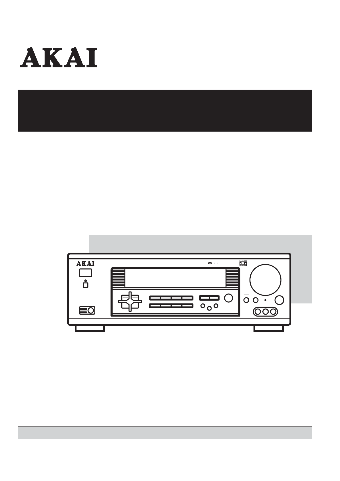
Operator's manual
AUDIO VIDEO CONTROL RECEIVER
AA-V2080
POWER
STANDBY
AUDIO VIDEO CONTROL RECEIVER AA-V2080
PHONES
MEMORY STATION
UP
STEREO
MONO
DISPLAY BAND
DOWN
MANUAL
BASS
TREBLE
VIDEO2 INPUT
BASSMGT.
MASTER VOLUME
VIDEO
RESET
AUDIOLR
BALANCE
RDS
1
2CH
INPUTMODE
SURROUNDMODE
DOLBYPRO LOGIC
AUTO
PHONO
AUXCDDVD
TUNER
VIDEO1 VIDEO2
6CHEXT.IN
TAPE
DOLBYDIGITAL
Operator's manual
1-17
Page 2
CAUTION: READ THIS BEFORE OPERATING YOUR UNIT.
(
)
IMPORTANT SAFETY INSTRUCTIONS
1. READ AND FOLLOW INSTRUCTIONS---All the safety and operation instructions should be read before the prod uct is operated.
Follow all operation instructions.
2. RETAIN INSTRUCTIONS---The safety and operation instructions should be retained for future reference.
3. HEED WARNINGS---Comply with all warnings on the product and in the operation instructions.
4. CLEANING---Unplug this product from the wall outlet before cleaning. Do not use liquid clea ners or aerosol cleaners. Use a damp
cloth for cleaning.
5. GROUNDING or POLARIZATION---This product may be equipp ed with a polarized alternating current line plug (a plug having o ne
blade wider than the other). This plug will fit into the power outlet only one way. This is a safety feature. If you are unable to insert the
plug fully into the outlet, try reversing the plug. If the plug should still fail to fit, contact your electricia n to replac e your obsolete outlet.
Do not defeat the safety purpose of the polarized plug.
6. OVERLOADING---Do not overload wall outlets or extension cord as this can result in a risk of
fire or electric shock. . Overloaded AC outlets, extension cords, frayed power cords, damaged
or cracked wire insulation, and broken plugs are dangerous. They may res ult in a shock or fire
hazard. Periodically examine the cord, and if its appearance indicates damage or deteriorated
receptacles, have it replaced by your service technician.
7. POWER SOURCES---This product should be operated only from the type of power source in dicated on the marking l abel. If you are
not sure of the type of power supply to your home, consult your product dealer or local Power Company. For products intended to
operated from battery power, or other sources, refer to the operation instructions.
8. ACCESSORIES---Do not place this product on an unstable surface or support. The product may fall,
causing serious injury to a child or adult as well as serious damage to the product. Any mounting of
the product should follow the manufacture’s instructions and use a mounting accessory
recommended by the manufacturer. A product and cart combination should be moved with care.
Quick stops, excessive force, and uneven surfaces may cause the product and cart combin ation to
overturn.
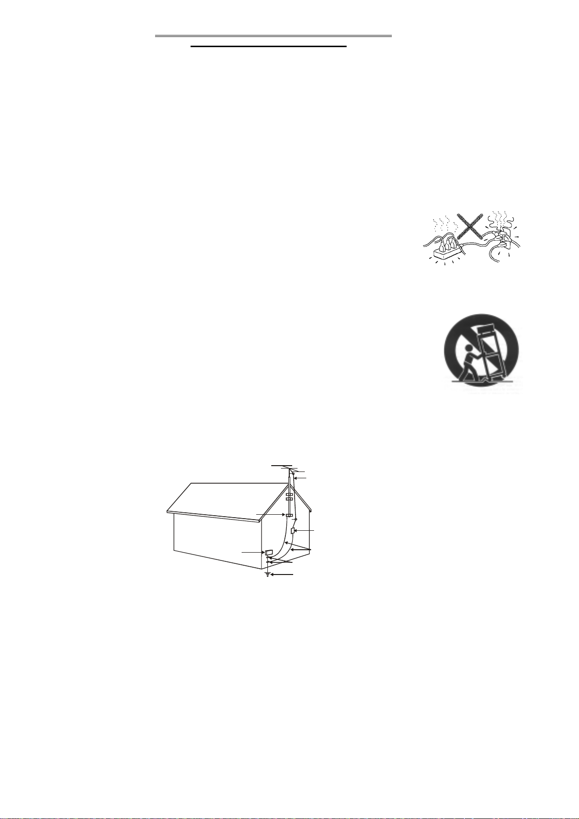
9. OUTDOOR ANTENNA GROUNDING---If an outside antenna or cable system is connected to the
product, be sure the antenna or cable system is grounded so as to provide some protection agai nst voltage sur ges a nd bui lt-up s tatic
charges. Section 810 of the National Electrical Code, ANSI/NIPA No. 70-1984 (section 54 of Canadian Electrical Code, Part 1)
provides information with respect to proper grounding of the mast and supporting structure, grounding of the lead-in wire to an
antenna-discharge unit, size of grounding conductors, location of antenna-discharge un it, connection to grounding electrodes, and
requirements for the grounding electrode. See the example.
ANTENNA
LEAD IN
WIRE
GROUND
CLAMP
ANTENNA
DISCHARGE UNIT
NEC SECTION 810-21
ELECTRIC
SERVICE
EQUIPMENT
GROUNDING CONDUCTO RS
(NEC SECTION 810-21)
GROUND CLAMPS
POWER SERVICE GROUNDING
ELECTRODE SYSTEM
(NEC ART 250 .PART H )
10. POWER-CORD PROTECTION---Power supply cord should be routed so that they are not likely to be walke d on or pinched b y items
placed upon or against them, paying particul ar attention to cords at plugs, convenience receptacles, and the point where the y exit
from the product.
A. The amplifier is equipped with the automatic protection circuit for safety purpose.
B. Depending on the recording level of the DVD DISK, the amplifier may reach to saturation causing the output sound distorted. For
good listening level, 2/3 of volume will be recommended.
11. ATTACHMENTS---Do not use attachments not recommended by the product manufacturer as they may cause hazards.
12. CONDITIONS REQUIREING SERVICE— Unplug this product from the wall outlet and refer servicing to qualified service personne l
under the following conditions.
A. When the power-supply cord or plug is damaged.
B. If liquid has been spilled, or objects have fallen into the product.
C. If the product has been exposed to rain or water.
D. If the product does not operate normally by following the operation inst ructions. Adjust only those controls that ar e covered by the
operation instructions. Improper adjustment of other controls may result in damage and will often require extensive work by a qualified
1
Page 3
technician to restore the product to its normal operation.
E. If the product has been dropped or damaged in any way, and
F. When the product exhibits a distinct change in performance--- this indicates a need for service.
13. Servicing ---Do not attempt to service this product yourself as opening or removing covers may expose you to dangerous voltage or
other hazards. Refer all servicing to qualified service personnel.
14 Lightning---For added protection for this product during a lightning storm, or when it is left
unattended and unused for long period of time, unplug it from the wall outlet and disconnect the
antenna or cable system. This will prevent damage to the product due to lightning and power line
surges.
15 Replacement Parts--- When replacement parts are required, have the service technician verify that
the replacement parts he uses have the same safety characteristics as the original parts. Use of replacements specified by the product
manufacturer can prevent fire, electric shock, or hazards.
16 Safety Check--- Upon completion of any service or repairs to this product, ask the service technician to perform safety checks
recommended by the manufacturer to determine that the product is in safe operating condition.
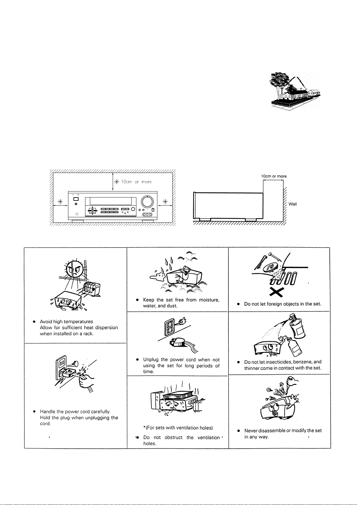
17 Heat Dispersal ---leave at least 10 cm of space between the top, back and sides of this unit and the wall or other components.
18 NOTE ON USE
2
Page 4

ABLE OF CONTENT
T
Safety Information P.1 - P.2
Table of Content P.3
General Information P.4
Panel information P.5 - P.7
Front Panel
Back Panel
Remote Control
P.5
P.6
P.7
Connection P.8 - P.9
Operation P.10
Switching on the Receiver
Playing the Analog Program Source
Playing the Digital Program Source
P.10
P.10
P.10
Using the Surround Function P.11 - P.12
Setting P.13 - P.14
Listening to the Radio P.15 - P.16
Other Operation P.16
Specification P.17
Total Pages: 17
3
Page 5

GENERAL INFORMATION
ACCESSORIES
- Analog audio cables x 2 (with red and white plugs)
- “2A” size batteries x 2 for the remote control
- Remote control
- Instruction Manual
- AM Loop Antenna
REMOTE CONTROL
The remote control enables you to activate the main functions of the system.
Some buttons are only available on the remote control device. In this case the respective functions can only be
activated via the remote control device.
The following should be noted when operating the system using the remote control:
Point the remote control (transmitter) towards the unit.
•
• Visual contact must exist between the transmitter and receiver.
If the range of the remote control decreases dramatically, replace the batteries with new ones.
•
Take part in environment protection!
Used batteries and accumulators (accus) don’t belong to the rubbish.
You can deliver them to the collecting point for used batteries.
Please inform yourself at your local community authority.
HEADPHONE SOCKET
Connection socket for headphones (6.3 mm. pin plug). Use commercially available adapters for other types of
plug.
4
Page 6
PANEL INFORMATION
AUDIO VIDEO CONTROL RECEIVER AA-2080
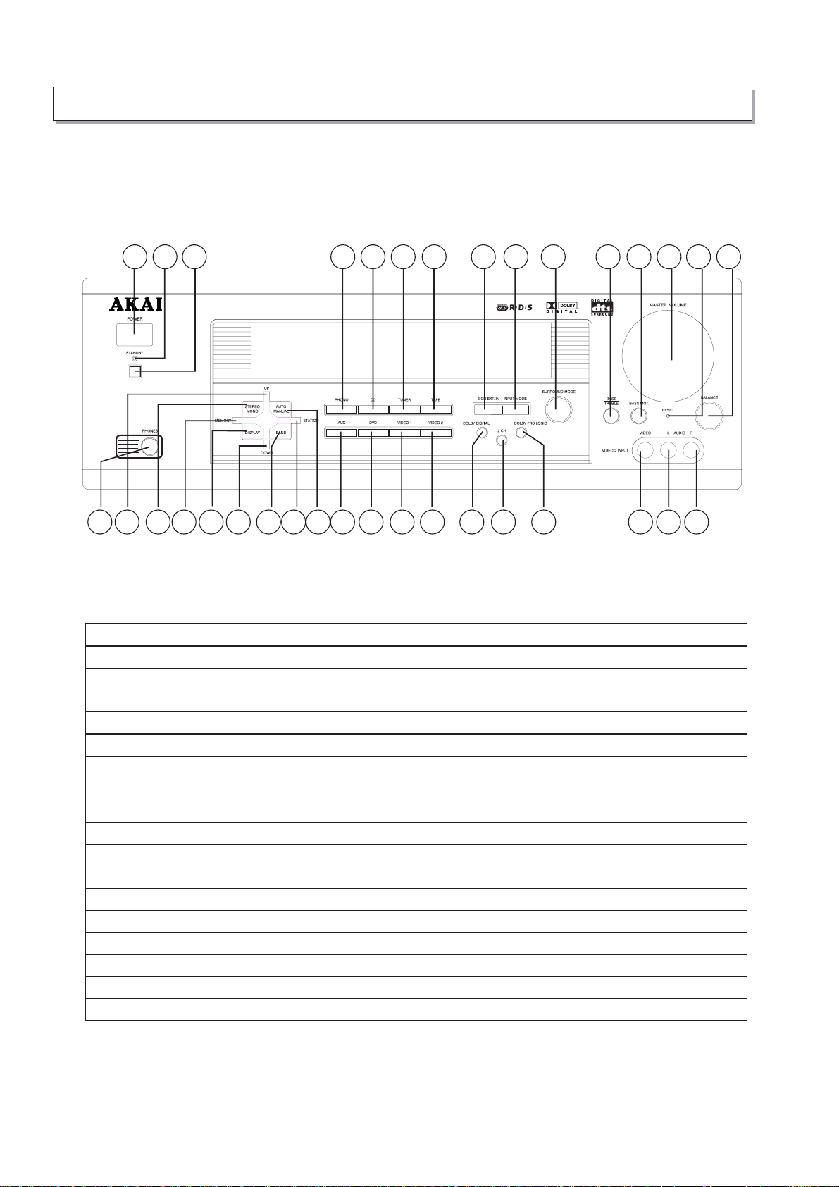
FRONT PANEL
1 2 3 4 5 6 7 8 9 10 11 121314 15
16 17 18 19
21 22 23 24 25 26 27 29 30 31 32 33 3428
20
1.POWERON/OFF 19.MEMORY
2. STANDBY INDICATOR 20. DISPLAY
3. STANDBY 21. DOWN
4. PHONO 22. BAND
5. CD 23. STATION
6. TUNER 24. AUTO / MANUAL
7. TAPE 25. AUX
8.6CHEXT.IN 26.DVD
9. INPUT MODE 27. VIDEO 1
10. SURROUND MODE 28. VIDEO 2
11. BASS / TREBLE 29. DOLBY DIGITAL
12. BASS MGT. 30. 2 CH
13. MASTER VOLUME 31. DOLBY PRO LOGIC
14. RESET 32. VIDEO 2 (VIDEO IN)
15. BALANCE 33. VIDEO 2 (AUDIO L IN)
16. PHONES 34. VIDEO 2 (AUDIO R IN)
17. UP
18. STEREO / MONO
5
Page 7

BACK PANEL
1. 6 CHANNEL EXTERNAL IN
Front L & R
-
7. COAXIAL IN
- Center
- Surround L& R
- Sub- Woofer
2. 75 OHM JACK FM ANTENNA IN 8. OPTICAL IN
3. AM LOOP L & R SOCKET 9. VIDEO
- MONITOR OUT
- VIDEO 1 IN
- DVD IN
4. ANALOG ADUIO IN
- Phono
- Video 1
- DVD
10. SPEAKERS CONNECTION IN
- Surround Speakers L & R
- Center Speaker
Front Speakers L & R
- CD
- AUX
- TAPE PLAY
- TAPE REC (Output)
5. S-VIDEO
11. CONNECTION TO MAIN POWER SUPPLY
- MONITOR OUT
- VIDEO 1 IN
- DVD IN
6. SUBWOOFER OUT
6
Page 8
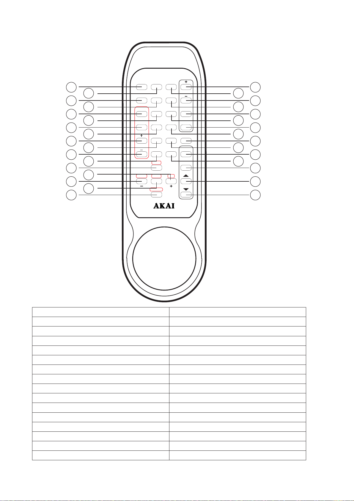
REMOT E CONTROL
124
12 18
225
13 19
326
14 20
427
15 21
528
16 22
629
17 23
730
8
931
10
11 32
POWER
ON/STANDBY
BASS
MGT
MUTE
DOLBY
APS DVD
DIGITAL
PRO
MEMORY
LOGIC
2CH
STATION
DYNAMIC
BAND
DOWNUPAUTO
STEREO
CD
TAPESURROUND
VIDEO
1/2
AUX/
PHONO
TUNER
DELAY .T
SPK
SETTING
SPK
ON/OFF
T. TONE
LFE
CH. TRIM
VOLUME
AA-V2080
1. POWER ON / STANDBY 17. DYNAMIC
2. MUTE 18. CD
3. APS 19. TAPE
4. MEMORY 20. DVD
5. STATION UP 21. VIDEO1/2
6. STATION DOWN 22. AUX / PHONO
7. BAND 23. TUNER
8. UP 24. DELAY TIME UP
9. DOWN 25. DELAY TIME DOWN
10. AUTO SEARCH 26. SPEAKER SETTING
11. STEREO 27. SPEAKER ON / OFF
12. BASS MGT 28. TEST TONE
13. SURROUND 29. LOW FREQUENCY EFFECT
14. DOLBY DIGITAL 30. CHANNEL TRIMMER
15. PRO LOGIC 31. VOLUME UP
16. 2 CHANNEL 32. VOLUME DOWN
7
Page 9

CONNECTION
PRECAUTION
- Disconnect the power cord from the power socket before any connection.
- The digital optical connection is less sensitive to external disturbance
- Loose connect may create noise when operating
The single small number in bracket is the key no. on back panel
-
CONNECTION TO AC POWER SUPPLY
- Connect the power cord to the AC main socket.
- The receiver is switched on and off by the POWER ON/OFF button (Front Panel label 1).
- Press STANDBY on the (Front panel label 3) or (Remote label 1) to switch on the unit.
CONNECTION TO ANTENNA
- Insert the AM antenna loop into the AM Loop Socket (Back Panel label 3)
CONNECTION TO ANALOG AUDIO / VIDEO
- You can connect the L & R output (except Tape Rec) of the following external player to the
AUDIO IN (Back Panel label 4) with a RCA cable:
ANALOGUE
PHONO (FOR TURN TABLE)
VIDEO (FOR CDV OR LD PLAYER)
DVD (Refer to the DVD connection above)
COMPACT DISC PLAYER (FOR CD PLAYER)
UX (FOR ANY EXTERNAL PLAY ER WITH A NALOG A UDIO O UTPUT
A
TAPE PLAY (FOR CASSETTE PLAYER)
TAPE REC (FOR CASSETTE RECORDING. CON NECT THE TAPE REC OUTPUT TERMINALS TO THE LINE IN
TERMINALS ON THE CASSESSTE DECK USING THE RCA CORD.)
)
* Upon connection, you should choose the external sources on the corresponding buttons on front panel
CONNECTION TO DIGITAL AUDIO
- Connect the OPTICAL IN (Back Panel label 8) or COAXIAL IN (Back Panel label 7) of this unit to the digital
output of your external player.
- Digital input signal can only be recognized when DVD, CD or VIDEO 1/2 is the input source.
- Use 75 ohm cable pin cords (sold separately) for coaxial connections
- Use optical cables (sold separately) for optical connections. (Remove the cap before connecting)
* At any one time, only two digital input signals can go into the machine (i.e. via Optical and/or Coaxial
IN)
CONNECTION TO EXTERNAL UNIT WITH 6 CHANNELS
- Left, Right, Central, L Surround, R Surround & the Sub-Woofer signal output of your external decoder with
6-channel output to the 6 CH EXT IN (Back Panel label 1)
CONNECITON TO TV AND VIDEO
- Connect the MONITOR OUT at VIDEO (Back Panel label 9) with a video cord or connect MONITOR OUT at
S-VIDEO (Back Panel label 5) with a S-video cord to the TV VIDEO IN of your TV set
- Connect the VIDEO 1 IN VIDEO IN (Back Panel label 9) / VIDEO 1 IN at S- VIDEO IN (Back Panel label 5) or
VIDEO 2 IN (Front Panel label 32) to the video output of your external players.
8
Page 10
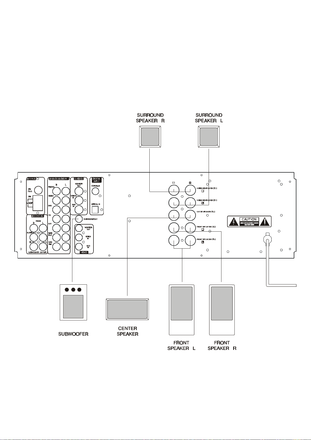
CONNECTION TO SPEAKERS
- Connect the cord between speakers to the unit at (Back Panel label 10) the SURROUND SPEAKERS R & L
(8 ohm), CENTER SPEAKERS (8 ohm) and FRONT SPEAKERS R & L (8 ohm) sockets on back panel.
CONNECTION TO SUBWOOFER
- Connect the cord between the subwoofer with built-in amplifier (super woofer) and this unit at SUBWOOFER
OUT (Back Panel label 6).
*To achieve DOLBY DIGITAL playback effect, use a unit that can sufficiently reproduce frequencies of under 80
Hz.
9
Page 11

OPERATION
(* The small numbers in bracket is the key no. on panel / remote control information respectively unless specify)
SWITCHING ON THE RECEIVER
Power On / Off
Press
Standby
POWER
(Front Panel label 1) to switch the unit on. The
STANDBY indicator LED
(2) will be lighted.
To start operating the unit, press STANDBY (Front Panel label1) or (Remote label 1). The Standby Indicator LED
will diminish. When switching on the amplifier, the volume will start at –50 dB.
PLAYING THE ANALOG PROGRAM SOURCE
1. Select the program source to be played before starting.
Source Selection (small no in bracket = key no. Front panel)
a. PHONO (Front Panel label 4)
It is for playing records from turntable
b. CD (Front Panel label 5)
It is for compact disc playback
c. TUNER (Front Panel label 6)
It is for radio listening
d. TAPE (Front Panel label 7)
It is for cassette recordings playback
2. To select analog input mode, press INPUT MODE (Front Panel label 9) until ANALOG IN is displayed
3. Start playing the selected component
4. Adjust the
MASTER VOLUME
by turning the round button (Front Panel label13) on front panel or the up /
down button (Remote label 31 or 32) on remote control
5. Press the BASS / TREBLE (Front Panel label 11) until you see TRB 0 dB for adjusting Treble or BAS 0 dB
for adjusting Bass.
Turn in clock-wise direction (Front Panel label 13) for increasing the bass or treble or vice versa
PLAYING THE DIGITAL PROGRAM SOURCE
1. Select the program source to be played before starting.
Source Selection (small no in bracket = key no. Front panel)
a. CD (Front Panel label 5)
It is for compact disc playback
c. DVD (Front Panel label 26)
It is for analog DVD playback
* Only 2 digital input can be used at every single time i.e. via the OPTICAL IN and COAXIAL IN
2. To select the digital input, press INPUT MODE (Front Panel label 9) until DIGITAL IN is displayed
3. Start playing the selected source
4. Adjust the MASTER VOLUME (Front Panel label 13) by turning the round button or press the up / down
button (Remote label 31 and 32)
e. AUX (Front Panel label 25)
It is for any analog external source
f. DVD (Front Panel label 26)
It is for analog DVD playback
g. VIDEO 1 (Front Panel label 27)
It is for video playback
h. VIDEO 2 (Front Panel label 28)
It is for video playback
d. VIDEO 1 (Front Panel label 27)
It is for video playback
e. VIDEO 2 (Front Panel label 28)
It is for video playback
10
Page 12

11
m, Theater and Hall.
SING THE SURROUNDING FUNCTION
U
DOLBY SURROUND
This unit is equipped with digital signal processing sections for decoding and reproducing movie soundtracks the
same way as in movie theaters.
Dolby Pro Logic
When using conventional video tapes, laser discs, TV programs or CDs with the mark, 3 Dolby Pro Logic
extremely natural sound movement and positioning, immersing you in the on screen action. Pro Logic uses a
directional emphasis circuit to decode four output channels (front left and right, center and surround) from the two
audio channels provided on the software.
This set is equipped with six Dolby Pro Logic play modes: Pass through, Movie, Music, Roo
You can select the optimum mode according to your preference.
Dolby Digital
When you connect the DVD player or an LD player with an DOLBY DIGITAL RF output to the DOLBY DIGITAL
RF input terminal and play DVD, laser discs with 1 mark, you can experience improved sound spatiality,
positioning, and impact compared with Pro Logic. This is because Dolby Digital delivers up to 5 totally discrete full
frequency audio channels (front left and right, center and surround left and right), plus a bass-only effect channel.
Since the signal is digital from the input of the program source until to the output of this unit, a higher quality and
clarity of surround sound results.
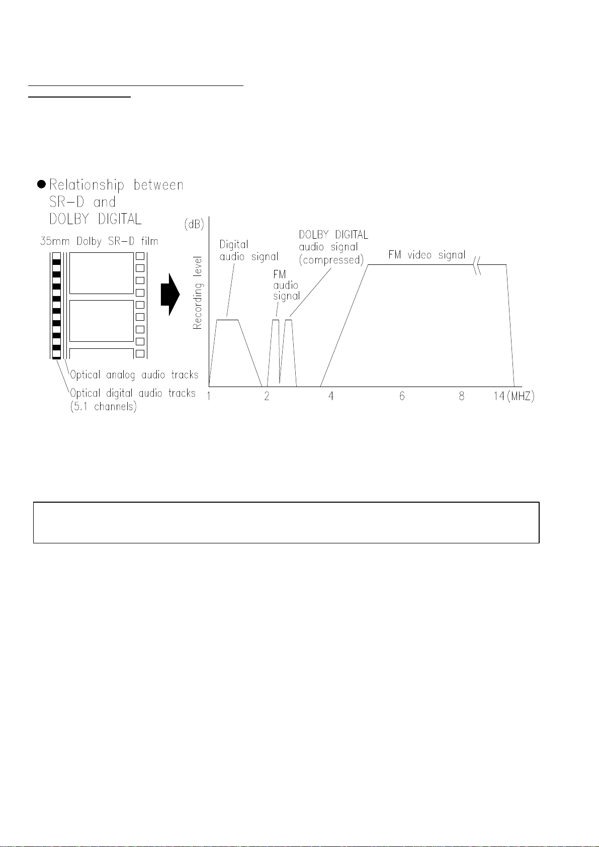
Dolby Digital is a system developed by Dolby Laboratories that transmits 5.1 channels of digital signals. The
surround system developed for movie theaters using this system is called “Dolby SR-D (Surround Digital)”.
Whereas the conventional Dolby Pro Logic Surround is an analog matrix system, Dolby SR-D is a digital discrete
system in which the different channels are completely independent. This makes it possible to achieve a realistic
sound field with a “three-dimensional” feel, giving the sound sense of distance, movement and relative position,
and creating a surprisingly real and powerful sense of presence when playing movie software in AV rooms.
There are 5.1 channels playback: three front channels (front left, center and front right), two surround channels
(surround left and surround right), plus “0.1 channel” called LFE (Low Frequency Effect) for low bass effect
sounds of 120 Hz or less. The signals are recorded on the software in fully discrete fashion, eliminating cross
talk between channels and making it possible to control the sound field in the listening/ viewing space with greater
precision.
In addition, the frequency range of the five channels extends up to 20kHz (the same as CDs), resulting in clear
sound with greater richness of expression.
Dolby Digital and Pro Logic
Home surround methods Dolby Digital Dolby Pro Logic
No. of recording channels
(material)
No. playback channels
Playback channels
Audio processing
Upper reproduction limit of
surround channel
5.1 channels 2 channels
5.1 channels 4 channels
L, R, C, SL, SR and SUB L, R, C, S (SUB recommended)
Digital Discrete processing, DOLBY
DIGITAL encoding / decoding
20 kHz 7 kHz
Analog matrix processing, Dolby
Surround
Page 13
12
Relationship between SR-D and DOLBY DIGITAL
35 mm Dolby SR-D film
Manufactured under license from Dolby Laboratories. “Dolby”, “Pro Logic” and the double-D symbol
are trademarks of Dolby Laboratories
Page 14

13
ETTING
S
TEST TONE
It is to adjust playback level from different speakers and is only effective in Dolby Pro Logic and Dolby Digital
modes.
1. Press
2. Press the
3. The adjustable range is between –10dB and +10dB.
* You will hear some noise like sound when adjusting.
T.TONE
(Remote label 28) repeatedly to see L, R, LS, RS, C, and SUB sequentially.
VOL UP / DOWN
(Remote label 31 and 32) to adjust the sound level of each speaker.
SPEAKER SETTING (SPK SETTING)
It is to select the speaker(s) to which the sound signal is sent out.
Press the
SPK SETTING
* It cannot be adjusted under analog mode
SPK SETTING
(Remote label 26) then
Display
C
(it means the center speaker)
SL / SR
(it means the surround left and right speaker)
SUB
(it means the subwoofer)
SPK ON / OFF
(Remote label 27) to get the followings:
SPK ON / OFF
Display
YES / NO
YES / NO
YES / NO
DELAY TIME (Delay T.)
It is to adjust each speaker’s response time to output signal.
Press
DELAY T. UP / DOWN
SPK SETTING
(Remote label 26) then
(Remote label 24 and 25) repeatedly to get the followings:
DELAY T.
(Remote label 24 and 25). Then adjust by pressing the
Display Display Display
C CDL 0, 1, 2, 3, 4, 5
SPK SETTING
* It will have no response after pressing DELAY T. if that speaker is not connected.
SL / SR SDL 0, 5, 10, 15 mS
SUB
DELAY T.
VOL UP
/ DOWN
mS
BASS MANAGEMENT
It is to set the speaker bass.
1. Press
2. Choose from Mode 0, 1 or 2 for different bass combination.
Front L & R Center Surround L & R Subwoofer
Mode 0 Large large large On
Mode 1 Small small small On
Mode 2 Large small small On
* Small: speakers that cannot reproduce low sound of below 80 Hz with sufficient volume
Large: speakers that can fully reproduce low sound of below 80 Hz
* The small and large indication does not refer tot he physical size of the speakers, but according to the bass
* The default speaker setting is mode 1
BASS MGT
reproduction capacity at 80 Hz.
(Remote label 12) to activate / off the bass of the speakers.
DYNAMIC RANGE CONTROL (DYNAMIC)
It is to adjust the compression of the output sound level to protect you from hearing too loud sound / voice.
Large the compression, smaller the output sound level.
Page 15

14
Default DRC values: 0/4, 1/4, 2/4, 3/4, 4/4.
0/4
1/4
2/4
3/4
4/4
Level of Compression Sound Level
Increasing Decreasing
LOW FREQUENCY EFFECT (LFE)
It can be adjusted when playing program sources recorded in Dolby Digital.
It can only be adjusted under 5.1 channels playback.
If the subwoofer clips due to the LFE signal during Dolby Digital playback, adjust the level as needed.
1. Press
2. You can select in 1 unit from –10 dB to 0 dB.
(Remote label 29). Then press the
LFE
VOLUME UP / DOWN
(Remote label 31 and 32) to adjust.
CHANNEL TRIMMER (CH. TRIM)
1. Press
MASTER VOLUME
2. If the master volume is not adjusted after 5 seconds, the display will back to normal automatically.
* Please note that if your DVD player has only 2 channels, then the amplifier can adjust left and right front
speakers only.
TRIM (Remote label 30), the display will show LS , RS, CCH, SW, LCH and RCH and then rotate
CH.
to adjust the volume. The volume can be adjusted from –10 dB to +10 dB
DOLBY DIGITAL
1. Select the source then start playing
2. Press
* This effect should be complementary with a Digital input signal and a digital disc with Dolby Digital encoded
STEREO
1. Select the source then start playing
2. Press 2 CH (Front Panel 30 or Remote label 11) to have stereo effect
* You can choose to have stereo output also with Digital input
MASTER VOLUME
It is to increase or decrease the master speaker volume by rotating the
13 or Remote label 31 and 32). The volume on the display will be changed accordingly.
The highest output is at 0 dB (
BALANCE
It is to adjust the balance of the left & right speakers volume.
² Turn the
speakers’ volume.
DOLBY DIGITAL
BALANACE
(Front Panel label 29 or Remote label 14) to activate the Dolby Digital function.
MASTER VOLUME
MAX VOL
knob (Front panel 15) clockwise or anti-clockwise to adjust the balance of the R & L
) and the lowest is at –79 dB (
MIN VOL
).
control (Front Panel
Page 16

LISTENING TO THE RADIO
Auto. Tuning
1. Select TUNER (Front Panel label 6) as the source.
2. Press BAND (Remote label 7) to choose AM/FM band frequency.
3. Press AUTO/MANUAL (Front Panel 24) or AUTO (Remote label 10) to select to have auto tuning or not.
4. For auto tuning, press UP/DOWN (Front Panel label 17 and 21) or (Remote label 14 and 16) to search
for your desired stations automatically.
(To operate manual search, press the UP/DOWN buttons the same and searches your favorite station.)
PRESET MEMORY
1. To store your selected stations, press MEMORY (Front Panel 19) or (Remote label 4) and
color will appear on the display.
2. Press UP/DOWN (Front Panel 17 and 21) or (Remote label 8 and 9) to choose the station number for
your desired station frequency . T he green musical calendar number
display is to show the station number.
3. Press MEMORY again to confirm.
4. You can store up to 15 stations for AM and FM band.
RECALLING PRESET STATION
1. Choose TUNER (Front panel 6) or (Remote label 23) as the source.
2. Press BAND (Remote label 7) to select AM or FM frequency.
3. Press STATION UP/DOWN (Remote label5 and 6) or press STATION (Front panel 23) then UP/DOWN
(front Panel 17 and 21) to go to your preset stations.
AUTO PRESET SEARCH (APS)
It is to allocate and memory radio station automatically. It will search the station with RDS broadcast first and
then search the other without.
1. Press APS (Remote label 3) to activate this function.
2. Then you will see SEARCH then the band frequency. The station found will be stored.
RDS DISPLAY (c/w RDS)
RDS is a method for the transmission for additional information via VHF stations. For example, name of the
station broadcasting will be shown on the multifunction display.
It can only function if the local broadcasting stations have the RDS transmission and the signal is strong
enough.
1. Press the DISPLAY (Front Panel 20) repeatedly to have PS (program name), WAIT CT.
2. The selected display mode will be flashing for 5 times until it searches your desired type.
3. NO PS, NO CT will appear after the flashing to show that function cannot be carried out. (E.g. due to
weak signal.)
1 , 2 , 3 ... on top of the
M in red
15
Page 17

DISPLAY (w/o RDS)
Digital (CD, DVD, VIDEO 1 & VIDEO 2) mode---Press this key to display the digital source of the
underplaying CD, DVD, VIDEO 1 & VIDEO 2.
PS (Station Name)
1. Press DISPLAY (Front Panel 20) until PS appears.
2. The current station name will be shown.
CT (Current Time)
1. Press DISPLAY (Front Panel 20), then WAITING CT will appear.
2. The current time will be shown e.g. 14:30.
OTHERS OPRERATION
MUTE (Remote label 2)
In order to stop all the voice, you can press MUTE button. The indicator will light up. If you press once more
or rotate the MASTER VOLUME, this function will be canceled.
PHONES JACK (front Panel Label 16)
Connect the plug on the stereo headphones for private listening. Adjust the volume so that it does not hurt
your ears when using the headphones. The loudspeakers are automatically switched off when headphones
are plugged in.
RESET (Front Panel Label 14)
If you find the amplifier has some problems or you want to back to the original setting, you can press RESET
while the amplifier is off. Pay attention!
In order to protect your amplifier, you must disconnect the power plug from the power outlet before you
press this button.
Note: OVER HEAT PROTECTION
The amplifier will turn off in case of over heat occurs, “ OVER HEAT PROTECTION” will be shown on the
display. The amplifier cannot be turned on until temperature inside falls down and clock is shown again on
the display.
16
Page 18

17
S
PECIFICATION
Audio Section
Rated Power Output :
(EIAJ) CENTER
Output Terminals : FRONT 8 ohm
CENTER 8 ohm
REAR 8 ohm
Total Harmonic Distortion : less than 0.05% at 1/2
rated power output
FRONT
REAR
80 W + 80 W
80 W
80 W + 80 W
Line Input (Each Line Input - FRONT SPEAKER OUT)
Input Sensitivity/Impedance :
Phono (MM):
Frequency Response : 20 Hz - 25 kHz +0.5 / -1 dB
Tone Control Range :
Signal-to-noise Ratio : 75 dB
150 mV / 47k Ω
2.5 mV / 47 K Ω
BASS: ±6 dB
TREBLE: ±6 dB
Phono Equalizer (PHONO Input – TAPE REC)
RIAA Deviation :
Rated Output : 150 mV
Signal-to-noise Ratio : 70 dB
± 0.5 dB
Woofer Output (Each Line Input – SUB-WOOFER OUT)
Rated Output/Impedance :
Frequency Response :
150 mV / 10K Ω
10 Hz - 300 kHz ± 3 dB
FM Tuner Section
Frequency Range : 87.5 - 108 MHz
Sensitivity : 14dB (5uV)
Antenna Terminal : 75 ohm (unbalanced)
AM Tuner Section
Frequency Range : 522 - 1629 kHz (Europe) 9 kHz step
530 – 1710 kHz (US) 10 kHz step
Sensitivity : 68 dB / M
Single-to-noise Ratio : 30 dB
Antenna : Loop Antenna
Video Section
Standard Video Jacks
Input and Output
Level/Impedance :
General
Power Requirements :
Power Supply : AC 220 - 230V ~ 50Hz (Europe)
Power Consumption : 280 Watts
Dimensions : 430(W) x 350(D) x 150(H) mm
Weight : 14Kg
*Design and specifications are subject to change without notice.
1 Vp-p / 75Ω
AC 110 – 120V ~ 60 Hz (US)
 Loading...