

AKA Sidewinder User Manual
Technical
Document
Sidewinder Specifications:
Model:
Version:
Gas Source:
Length:
Width:
Weight:
Adjustable Range:
Max Input:
**There are different length endcaps available for the Sidewinder
so the total length can be shortened or lengthened for a more
custom fit to the end user.
Sidewinder
A
Compressed air, Nitrogen or
2
CO
4.875 inches (total length)*
1” dia main body/1.125” dia
swivel sleeve.
0.308 lbs (with QD)
0-700 PSI
800 PSI
Adjusting the Sidewinder Regulator:
To decrease output when looking at the regulator from
the bottom, turn the allen wrench clockwise to decrease
the pressure. To increase output when looking at the
regulator from the bottom, turn the allen wrench counter
clockwise to increase the pressure.
Trouble Shooting:
Disassembly of Sidewinder Regulator:
To properly disassemble the Sidewinder regulator and
not scratch the outside, you will need a few items: Two
pieces of 2x4s about 4 inchs long, a cloth strap wrench,
a bench vise, a good adjustable wrench, and a set of
allen wrenches.
1. Remove all air sources.
2. Clamp the reg. body upper and reg. middle between
the two pieces of wood. The wood will keep the
regulators outside surface from getting scratched up.
3. Using the adjustable wrench on the swivel nut unscrew the swivel assembly from the bottom of the
regulator. Once loose unscrew the two pieces. Be careful
not to lose the reg. washer and the o-ring that are on
the inside this portion of the regulator.
4. Reclamp the regulator between the two pieces of
wood, clamp on the reg. body upper. Using the strap
wrench loosen the reg. body middle from the reg. body
upper. Inspect the o-rings for damage or wear. Replace
if needed.
Remember to shoot the gun several times after any
adjustment to the Sidewinder regulator so you can see
what the velocity settles in at. If the regulator creeps in
pressure range, check to make sure there is not a piece
of debris in between the regulator seat and the regulator
piston. Make sure the vent hole on the side of regulator
body middle is open and clean. If it is plugged the
regulator will not fuction properly.
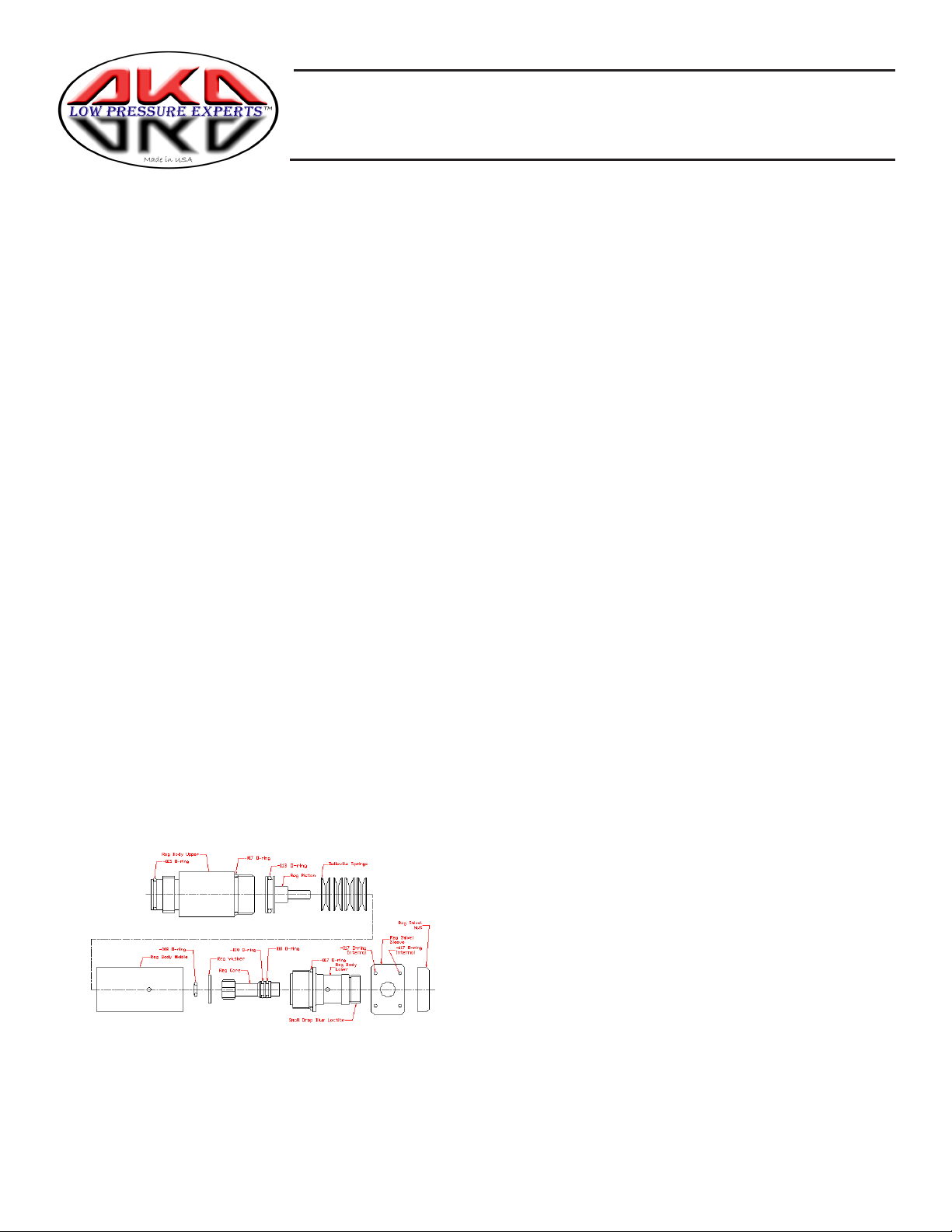
Schematic and Parts Chart:
(1) Regulator body upper
(1) -017 o-ring 1 -015 o-ring
(1) Regulator body middle
(1) -008 o-ring
(1) Regulator piston
(1) -113 o-ring
(8) Belleville springs
(1) Regulator washer
(1) Regulator Sleeve
(2) -017 o-ring
(1) Male Quick Disconnect
(1) Regulator body lower
(1) -017 o-ring
(1) Regulator core
(2) -010 o-ring
(1) 10-32 set screw
5. Once the two halves are separated you can remove
the piston and springs from the regulator body middle.
Be careful not to damage the piston or the o-rings.
Remember in what order the parts came out of the
regulator. Replace o-rings or springs if needed.
6. To disassemble the swivel joint, clamp the threaded
end of the swivel between the two pieces of wood. Use
the adjustable wrench to loosen the swivel nut. The
swivel nut is BLUE LOCTITED in place.
7. Using a gentle twisting action gently pull the swivel
sleeve from the regulator body lower. Inspect the o-rings
for damage or wear. Replace if needed.
8. Use an allen wrench and unscrew the regulator core
from the regulator body lower. The core comes out
through the front of the regulator body lower. Do not try
backing it out. Be careful not to damage any o-rings. If
needed replace the o-rings or if the reg. seat is damaged
replace the whole core assembly.
9. You can now replace the major components to the
regulator if needed. The regulator goes back together
easily. Use the strap wrench to tighten. Do not overtighten, just snug down and use a drop of blue loc-tite
on the threads to keep the regulator bodies tight
together.
 Loading...