

AKA Excalibur Viking, Viking Excalibur User Manual

2004
Excalibur and Viking Manual
Version 3.0
Nov 2003
EXCALIBUR®, VIKING™, TORNADO® VAL VE (p at#5791328), LIGHTNING BOLT®, SODA
CAN MOD/SCM™ and SIDEWINDER®(pat pend) are T rademarks or Registered Trademarks
of AKALMP, Inc. Design rights and all rights reserved. All patterns, drawings, photographs, instructions or manuals remain the intellectual property of the manufacturer . Covered under US
Patent 5791328 and other Patents Pending. All rights will be strictly enforced.
All rights reserved. No part of this work covered by the copyright hereon may be
reoproduced or used in any form or by any means without the written permission of
AKA.

I. Safety Guidelines & Instructions
II. Specifications
III. Operating instructions
A. Power Supply
B. Compressed Air/Nitrogen Supply
C. T urning “ON & FIRING” the Marker
D. Velocity Adjustment
IV. Electronics
A. Equalizer Board
B. Nelson Board
V. Maintenance
A. Cleaning
B. Sidewinder
C. Ball Detents
D. SCM™ / LPR
E. Tornado Valve
F. Lightning bolt
G. Excalibur Hammer
H. Viking Hammer
I . Excalibur Ram
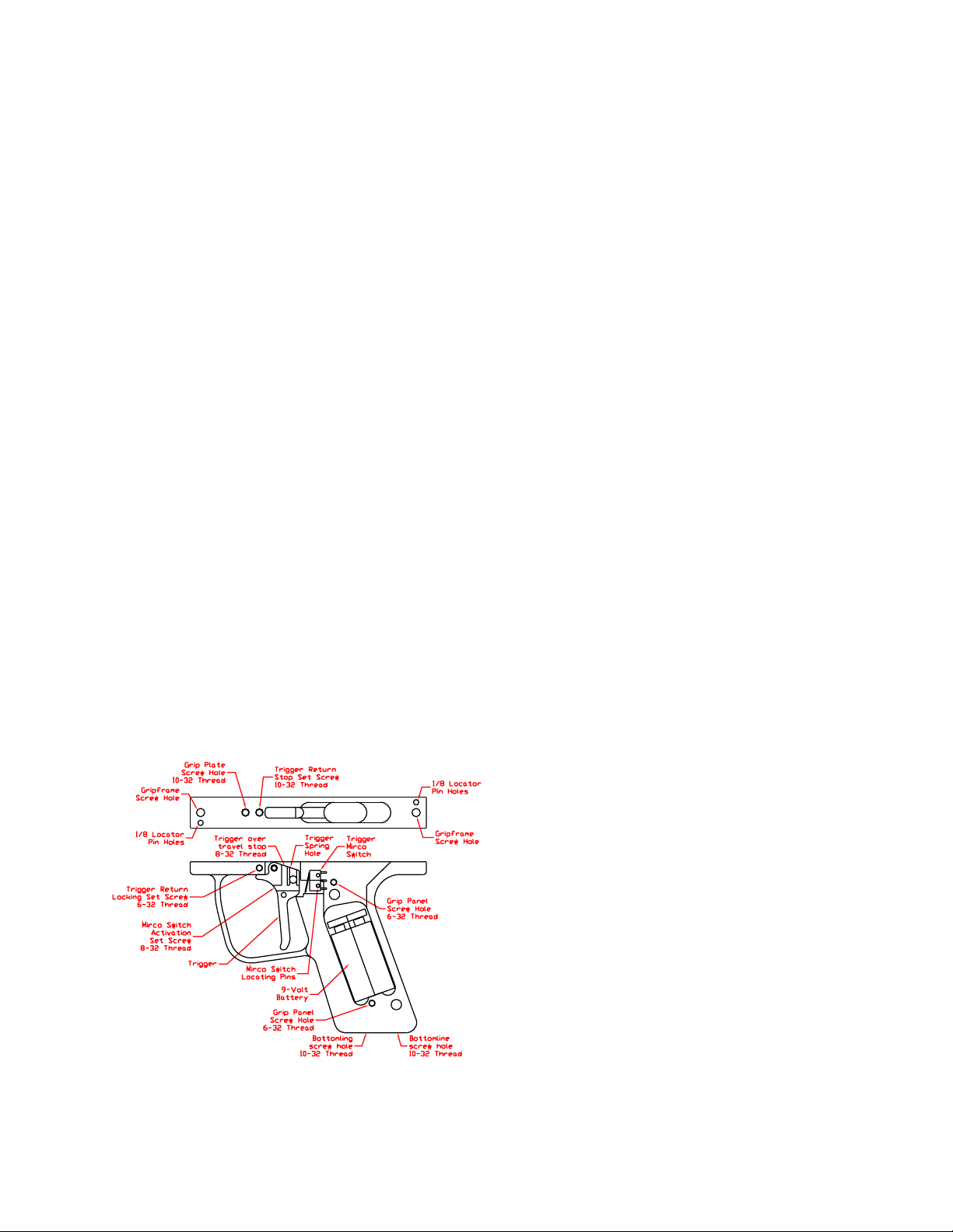
J. Trigger Frame
K. Solenoid valves
L. O-rings and Screws
VI. T roubleshooting
VII. Schematics
A. 2004 Excalibur®
B. 2004 Viking™
VIII. Warranty , Liability and Cont act Information
CONTENTS

Introduction:
Congratulations on purchasing an EXCALIBUR® or VIKING™ paintball marker . We hope you
enjoy using this marker. Please read the information in the manual and get familiar with you
marker before use.
This manual covers both the EXCALIBUR® and VIKING™ series of paintball markers as well as
covering the SIDEWINDER® regulator and the SCM™ low pressure pneumatics regulator. This
manual includes information for both the 2000-2003 and the 2004 models of EXCALIBUR® and
VIKING™. This manual is a work in progress and will be continuously updated as needed. If you
have suggestions to help improve this manual contact us through e-mail and let us know . W e
decided to place the manual on disk for the simplicity of keeping it up to date and to eliminate
paper waste.
The specifications and photographs in this material are for information and general guidance
purpose only . Our products are continually updated and changes may be made to specification,
design or appearance from time to time. These changes are subject to change without notice.
AKALMP reserves the right to revise and improve its products as it sees fit.
EXCALIBUR®, VIKING™, TORNADO® VAL VE (p at#5791328), LIGHTNING BOLT®, SODA
CAN MOD/SCM™ and SIDEWINDER®(pat pend) are T rademarks or Registered Trademarks
of AKALMP, Inc. Design rights and all rights reserved. All patterns, drawings, photographs,
instructions or manuals remain the intellectual property of the manufacturer. Covered under US
Patent 5791328 and other Patents Pending. All rights will be strictly enforced.
I. SAFETY GUIDELINES &
INSTRUCTIONS.
SAFETY GUIDELINES & INSTRUCTIONS FOR SAFE HANDLING OF EXCALIBUR® &
VIKING™ MARKERS.
• The EXCALIBUR® and VIKING™ are not toys.
• Careless or improper use, including failure to follow instructions in the operators manual, could
cause serious injury or death.
• Paintball industry standard head/face/throat/eye/ear protection designed specifically for paintball
meeting ASTM st andard F1776 must be worn by user and any person within range of any paintball
marker .
• Do not shoot at a person at close range.
• Observe all local laws, regulations and guidelines.
• Use only on paintball fields where safety rules are strictly enforced.
• Y ou must be at least 18 years of age to purchase the EXCALIBUR® or VIKING™.

• Individuals under 18 years of age must have adult supervision when using or handling the
EXCALIBUR® or VIKING™.
• Use only nitrogen and compressed air from approved storage bottle. Do not use CO2.
• Do not exceed 850 psi input pressure.
• Read operator’s manual before use and comply with all safety instructions.
• Use .68 caliber paintballs only.
• Always keep EXCALIBUR® or VIKING™ turned off when not in use.
• Always switch gas source of f when EXCALIBUR® or VIKING™ is not in use.
• Treat ever EXCALIBUR® or VIKING™ as if it is loaded.
• Never point the EXCALIBUR® or VIKING™ at anyone or anything you do not intend to shoot.
• Use approved barrel blocking devices on the EXCALIBUR® or VIKING™ when not in use.
• Never shoot at velocities in excess of 300 FPS.
• Never put fingers or any foreign objects into the paintball feed tube.
• Always remove all paintballs from the EXCALIBUR® or VIKING™ when not in use on or off the
field.
• Regulators and LPR’s can store gas after the bottle has been removed. Always degas
EXCALIBUR® or VIKING™ when not in use or before working on the markers.
• When adjusting, servicing or using the Excalibur, AL W A YS WEAR EYE PROTECTION
• Before doing any work to the Excalibur® (pat pend), make sure it is turned off, the air source
has been removed, and all paintballs have been removed.
• Seek professional assistance for advice if you are unsure of anything.

II. SPECIFICATIONS.
2000-2003 EXCALIBUR SPECS:
• Model: Excalibur®(pat. pending)
• Version: A
• Caliber: .68
• Action: Closed Bolt Electro-pneumatic
Operation
• Gas Source: Compressed air or Nitrogen
• Power Supply: 9 V olt battery
• ROF (Cyclic Rate): 13+BPS
• Standard Barrel Length: 12.0" Javelin
(AC Threads)
• Length: 8.0 inches
• Height: 8.4 inches (T op of feed tube to
bottom of grip)
• Width: 1.75 inches
• Weight: 3. lbs (Without battery & barrel)
• Operating Pressure: 140-180 PSI @ 280
FPS (depending on paint size)
• Input PSI to SIDEWINDER: 400-850 PSI
• Pneumatics Pressure: 65-85 PSI
Features:
• Tornado® Valve(Pat. #5791328)
• Lightning® Bolt (Delrin) with Quick Release
Pin
• Javelin™ Barrel
• 45 Grip
• Wire Ball Detent
• Built-In V ertical Mount
• SIDEWINDER®(pat pend) V ertical
Pressure Reg.
• Threaded V ertical Feedtube
• Adjust able Trigger (3 adjustment points)
• Adjustable WAS circuit board
• Adjustable Pneumatics Low Pressure
Regulator (LPR).
• Pull Through Cleaning
• Easy Disassembly & Low Maintenance
• Rugged Design
• Barrel Plug
• Carrying Case
2004 EXCALIBUR SPECS:
• Model: Excalibur®(pat. pending)
• Version: B
• Caliber: .68
• Action: Closed Bolt Electro-pneumatic
Operation
• Gas Source: Compressed air or Nitrogen
• Power Supply: 9 V olt battery
• ROF (Cyclic Rate): 13+ BPS
(unlimited ROF with EYE’s)
• Standard Barrel Length: 12.0" Javelin
(AC Threads)
• Length: 7.25 inches
• Height: 8.3 inches (T op of feed tube to
bottom of grip)
• Width: 1.75 inches
• Weight: 3 lbs (Without battery & barrel)
• Operating Pressure: 140-180 PSI @ 280
FPS (depending on paint size)
• Input PSI to SIDEWINDER: 400-900 PSI
• Pneumatics Pressure: 65-85 PSI
Features:
• Tornado® Valve(Pat. #5791328)
• Lightning® Bolt (Delrin) with Quick Release
Pin
• Javelin™ Barrel
• 45 Grip
• Dual ball Detent for centering the ball in the
breech
• Built-In V ertical Mount
• SIDEWINDER®(pat pend) V ertical
Pressure Reg.
• AKA Threaded V ertical Feedtube
• Adjust able Trigger (3 adjustment points)
• Adjustable WAS circuit board
• Ready to install Anti-chop eyes.
• Adjust able SCM™ Low Pressure
Regulator (LPR).
• Pull Through Cleaning
• Easy Disassembly & Low Maintenance

2001-2003 VIKING™ SPECIFICATIONS:
• Model: Viking™(pat pend)
• Version: A
• Caliber: .68
• Action: Open Bolt Electro-pneumatic
Operation
• Gas Source: Compressed air or Nitrogen
• Power Supply: 9 V olt battery
• ROF (Cyclic Rate): 13+BPS (unlimited
ROF with EYE’s)
• Standard Barrel Length: 12.0" Javelin
(AC Threads)
• Length: 8.0 inches
• Height: 8.4 inches (T op of feed tube to
bottom of grip)
• Width: 1.75 inches
• Weight: 3. lbs (Without battery & barrel)
• Operating Pressure: 140-180 PSI @ 280
FPS (depending on paint size)
• Input PSI to SIDEWINDER: 400-850 PSI
• Pneumatics Pressure: 65-85 PSI
2004 VIKING™ SPECIFICATIONS:
• Model: Viking™(pat pend)
• Version:B
• Caliber: .68
• Action: Open Bolt Electro-pneumatic
Operation
• Gas Source: Compressed air or Nitrogen
• Power Supply: 9 V olt battery
• ROF (Cyclic Rate): 13+BPS (unlimited
ROF with EYE’s)
• Standard Barrel Length: 12.0" Javelin
(AC Threads)
• Length: 7.5 inches
• Height: 8.3 inches (Top of feed tube to
bottom of grip)
• Width: 1.75 inches
• Weight: 3. lbs (Without battery & barrel)
• Operating Pressure: 140-180 PSI @ 280
FPS (depending on paint size)
• Input PSI to SIDEWINDER: 400-850 PSI
• Pneumatics Pressure: 65-85 PSI
Features:
• Tornado®Valve (Pat. #5791328)
• Lightning® Bolt(Delrin) with Quick Release
Pin
• Javelin™ Barrel
• 45 Grip
• Wire Ball Detent
• Built-In Vertical Mount
• SIDEWINDER®(pat pend) V ertical
Pressure Reg.
• Threaded V ertical Feed tube
• Adjust able Trigger (3 adjustment points)
• Adjustable Equalizer circuit board
• Adjustable Pneumatics Low Pressure
Regulator (LPR).
• Pull Through Cleaning
• Easy Disassembly & Low Maintenance
• Rugged Design
• Barrel Blocking Device
• Carrying Case
Features:
• Tornado® Valve(Pat. #5791328)
• Lightning® Bolt (Delrin) with Quick Release
Pin
• Javelin™ Barrel
• 45 Grip
• Dual ball Detent for centering the ball in the
breech
• Built-In V ertical Mount
• SIDEWINDER®(pat pend) V ertical
Pressure Reg.
• AKA Threaded V ertical Feedtube
• Adjust able Trigger (3 adjustment points)
• Adjustable Equalizer circuit board
• Ready to install Anti-chop eyes.
• Adjust able SCM™ Low Pressure Regulator
(LPR).
• Pull Through Cleaning
• Easy Disassembly & Low Maintenance
III. OPERATING INSTRUCTIONS.
A. POWER SUPPLY:
The ECALIBUR® and VIKING™ uses a 9-volt
battery stored in the grip as its power supply .
For maximum number of shots and velocity
stability you should only use high quality
alkaline batteries.
Installing a Battery:
Step 1: Make sure the marker is unloaded,
de-gassed and turned off. Remove one of the
two screws holding the grip panel on the left
side of the marker . Rotate the panel out of the
way . Remove the 9-volt battery from the
battery cable. Make sure not to pull the
battery cable apart.
Step 2: Inst all the new 9-volt battery on the
battery cable and place it back into the grip
frame. Make sure no wires on the battery
cable are pinched. Gently loop the wiring and
lay it on the side of the battery .
Step 3: Rot ate the grip panel back into place.
Then replace the grip panel screw . Y our
EXCALIBUR® and VIKING™ is now
powered and ready to use.
B. COMPRESSED AIR/NITROGEN
SUPPLY.
The EXCALIBUR® and VIKING™ are
designed to operate on nitrogen or
compressed air . It requires a high flow of
CLEAN gas. Most adjustable nitrogen
systems or preset bottle systems, will work
fine. The EXCALIBUR® and VIKING™ are
supplied with a SIDEWINDER® regulator
which has been designed to work at the low
pressure range in which the EXCALIBUR®
and VIKING™ operate. The input pressure to
the SIDEWINDER® regulator should be 400
to 500psi if you have an adjustable nitrogen
system. If you have a preset bottle then the
850 psi input is okay but the Low Pressure
450 nitrogen bottles are better .
CAUTIONS:
Air supplied at fields and tournament s is
often dirty if a compressor is used. Scuba air
is not always clean either . This dirty air is one
reason for paintball guns and regulator
failures. Next time your gun or regulator fails
at a tournament, stop - before blaming the
manufacturer of the paintball gun or regulator ,
and check your air supply . Some of this dirt
eventually ends up in the marker . Electronic
markers with solenoid valves are particularly
vulnerable to dirt. For this reason, we
recommend a portable filter such as the
GUARDIAN™ for filling your nitrogen system
or a nitrogen system with a built-in filter when
using the EXCALIBUR® or VIKING™.
Most metal fittings and steel braided hoses
are nickel-plated brass which can leave metal
shaving in your marker when you install a
hose. Always run air through the hoses and
fittings before attaching them to a marker to
make sure the air line is clear of debris. Metal
shaves can damage the internals of the
marker .

Use only steel braided hose and stainless
steel quick disconnects or Macro-line. Micro-
line restricts airflow and unsafe for use in
paintball.
DO NOT USE TEFLON TAPE. Improper use
of T eflon t ape can result in pieces of tape
going through the regulator and into the
marker. This can cause blockages and
damage to solenoid valves.
Do not use of pro-connects and fittings like
those, they restrict airflow which can cause a
drop in efficiency or can cause drop off
problems while firing the EXCALIBUR® or
VIKING™. They do not have a high enough
airflow for low pressure markers.
SIDEWINDER®(pat pend) regulator mounted
vertically in front of the trigger frame. The
SIDEWINDER®(pat pend) regulator is
standard on the EXCALIBUR® and VIKING™
and is adjusted in this fashion while looking at
the bottom of the SIDEWINDER®(pat pend)
regulator . When making velocity adjustments
you should use extremely fine adjustments so
as not to go past the desired velocity . If you
are unsure where your operating pressure is,
simply turn the pressure down until the velocity
drops to about 200 fps then slowly turn the
pressure back up.
Do not exceed a
velocity of 300 FPS.
C. T urning “ON” the marker.
1. After making sure the marker is unloaded
and de-gassed and you have installed the
battery .
2. Turn on the air source. On the
EXCALIBUR®, if the bolt is not in its forward
position it will now move forward closing the
breech. The bolt on the VIKING™ will move to
the rear of the marker.
3. Pointing the marker in a safe direction
away from you and others. Turn the marker
“ON” using the recessed power switch on the
side of the marker or in the back of the
marker. When the LED st arts blinking then the
marker is ready to fire.
4. The paintball marker is now ready to fire.
1. Turning the adjuster screw clockwise will
lower the pressure, thus lowering the velocity .
2. T urning the adjuster screw counterclockwise will increase the pressure raising
the velocity .
5. Simply point in a safe direction and pull the
trigger. Always keep your finger out of the
trigger guard when you are not firing the
paintball marker .
D. Velocity adjustment.
The velocity of the EXCALIBUR® and
VIKING™ is controlled directly through the

IV. ELECTRONICS:
TM
Equalizer
Installation and Usage Manual for
AKA Viking and Excalibur
EqualizerTM is a trademark of Wicked Air Sportz
All material including, but not limited to photographs, text, and concepts contained in this manual
is copyright ©2002-2003 By Wicked Air Sportz and Jim Drew. Distribution of this data without
permission is strictly prohibited! All rights reserved, worldwide. Reprinted with permission. This
section provided by Wicked Air S portz http://www .wickedairsportz.com/home.htm.

Introduction
Liability
Thank you for purchasing the EqualizerTM board.
This board is a direct replacement for the stock
circuit board found in your AKA marker .
Please read through this entire manual before
you attempt the installation of your Equalizer
TM
board!
Installation Requirements
T o install your Equalizer
TM
board, you will need
the appropriate sized allen wrenches and a flat,
clean, work surface.
The installation of the EqualizerTM board is not
difficult. If after reading through this manual, you
believe you cannot perform the installation,
please seek someone who can assist you.
This manual should provide ample information
and clarity to install this product.
By using this product, you agree to hold
Wicked Air Sportz free from any type of
liability either directly or indirectly due to
the use of this product.
SECTION 1 – INSTALLATION
Step 1 – Removing the Grip Frame
Before disassembling the marker, make
sure the marker power switch is in the off
position.
Remove the two screws that hold the grip frame
to the body .
Step 2 – Removing the Circuit Board From
the Grip Frame Tray
Two plastic screws are used to hold the circuit
board in place. Using the proper size flat tipped
screw driver, carefully remove the screws that
holds the circuit board in place.
Warranty Information
The EqualizerTM board carries a limited lifetime
warranty . Units subject to improper installation,
misuse, abuse, or modifications will not be
covered under this warranty .
Wicked Air Sportz may at its discretion either
repair or replace the unit. The customer will pay
all freight charges to and from Wicked Air
Sportz.
All defective units will be returned to the
customer via USPS Priority Mail. At the time of
printing this manual, this rate is $4.40. This
amount must be included with any unit to be
repaired, or the unit will be returned UPS COD/
Freight collect.
Once the screws are removed, gently pull up on
the circuit board assembly to give yourself
enough room to grab a hold of it.
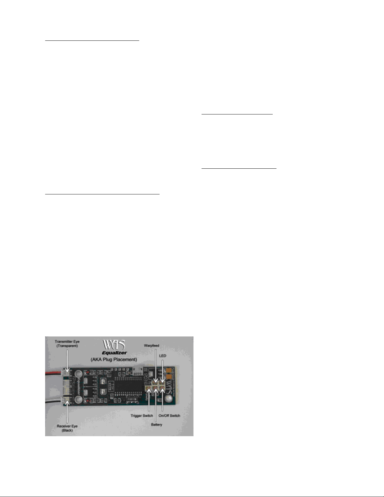
Step 3 – Disconnecting/Connecting the
Plugs
Carefully remove each connector from the stock
board (one by one) and place each connector
in the same socket location on the Equalizer
board. Refer to Figure 1 for proper plug
placement.
Step 4 – Mounting the Board Into the Grip
Frame Tray
Carefully press the EqualizerTM into the area
designed for the circuit board to fit in. Make
sure that you do not pinch any wires in the
harness. Line up the holes (opposite corners
of the EqualizerTM). Now, insert the plastic
screws into the holes and tighten the screws
until they are just snug. DO NOT
OVERTIGHTEN!
Step 5 – Testing the Board
Before reassembling the marker, you should do
a quick test to make sure that connections are
correct and that the board is working. Making
sure that nothing is grounding the grip frame,
move the power switch to the on position. If
everything is working, you should see the LED
light up orange. If this occurs, turn the power
switch to the off position and continue to step 6.
If you don’t see the LED light up, make sure
your battery is connected. If that is not the
problem, then check the connector plugs. If you
require further assistance, please email the
technical support department
(tech@wickedairsportz.com).
Step 6 – Reassemble the Marker
Reassemble your marker by attaching the grip
frame to the body , and using the two screws to
hold them together.
Congratulations! You have now successfully
completed the installation of your Equalizer
TM
board!
SECTION 2 – USAGE
The EqualizerTM has numerous features,
which can be a bit overwhelming to those
that are not use to having so much
flexibility .
The Boot Sequence
When the EqualizerTM boots up, the LED will light
up orange and then either green (NORMAL
mode) or red (COMPETITION mode).
Feature Descriptions
Dwell
Dwell is the amount of time that the
solenoid will be activated. This time is
measured in milliseconds (1/1000th of a
second). The user can alter the Dwell only
when in NORMAL mode. In COMPETITION
mode, it is not possible to change settings
via the trigger programming. The factory
default is 8.0ms. Changes can be made in
.1ms units via the Equalink.
NOTE: The Equalizer board can be used with
either the Viking or Excalibur markers. The
Equalizer detects which marker it is installed
in, and adjusts parameters to handle the
different firing sequences and eyes modes.
Increasing your Dwell will increase the
velocity of your marker. If you are
experiencing a great variance in your
chrono results, try increasing your Dwell.
If your dwell is too low, consistency will
suffer greatly .
Debounce
Debounce is the amount of time the trigger
switch must be stable in the up position
before checking for another trigger pull.
This time is measured in milliseconds. The
user can alter the Debounce only when in
NORMAL mode. Possible values are from
1ms to 255ms. The factory default is 10ms.
Changes are made in 1ms units.
If you find that your marker is double firing,
increase the Debounce time. T o make your
marker fire faster due to being more

responsive to the trigger, decrease the
Debounce time.
Remember, if you pull the trigger once and
the recoil causes your marker to fire again
by itself, it is NO LEGAL for tournament play
and is a SEVERE SAFETY HAZARD!
Eye Mode
The Eye Mode is can be set to one of four
different modes for the VikingTM:
Bypass - The anti-chop system is disabled.
When this occurs, the maximum rate of fire
is limited to 13 balls per second to help
prevent chopping of balls in the breech.
Delayed – This is like the normal method
of firing used in the original Intimidator
select fire and semi-only boards. If you pull
the trigger and noball is found in the
breech within ¾ of a second, the marker is
fired anyways. If a ball is found before the
time expires, the marker will immediately
fire (before the ¾ of second time is up). This
is the default eye mode.
Forced – In this mode, the marker will not
fire unless there is a ball in the breech. In
this mode, your marker will not “dry fire”
ever. This is the recommended eye mode.
Simulate – In this mode, a ball is simulated
to be in the breech. This allows you to fire
the marker with just air, at the full speed that
the marker is capable of firing! This mode
can be used for practicing trigger pull
methods, without wasting paint. DO NOT
SHOOT P AINT IN THIS MODE!
common, this does happen enough to
justify the creation of this mode. The
factory default is Delayed.
The Eye Mode can be set to one of four
different modes for the Excaliburâ:
Bypass - The anti-chop system is disabled.
When this occurs, the maximum rate of fire
is limited to 10 balls per second to help
prevent chopping of balls in the breech.
Normal – In this mode, the chambered ball
will fire (if there is one) and the bolt will open
for up to ¾ of a second before automatically
closing. If a ball is found before this time
expires, the bolt will immediately close.
This is the default eye mode.
Classic – In this mode, the chambered ball
will fire (if there is one), and the bolt will stay
open as long as you keep holding the
trigger (just like a stock Autococker).
Sniper – In this mode, the chambered ball
will fire (if there is one), and the bolt will not
cycle until you release the trigger. When
the trigger is released, bolt will open for up
to ¾ of a second before automatically
closing. If a ball is found before this time
expires, the bolt will immediately close.
NOTE: IN ALL CASES, IF YOU DO NOT
HAVE AN EYE SYSTEM, THE COMPUTER
WILL AUTOMATICALLY SWITCH TO
BYP ASS MODE!
It is highly recommended that tournament
players use the Forced mode. Ifyou have
a hopper jam or something hangs up in the
feed tube, and you are using Delayed
mode, it is possible to chop a ball if one
breaks free at the instant the firing
sequence starts. Although this is not
Hopper Trigger
The EqualizerTM hardware has the ability to
generate a positive or negative going
pulse, for a duration that is user
programmable. Although the Equalizer
TM

cannot supply power to your hopper to run
it (in place of its own batteries), it can
provide a trigger that could force activation
for a programmable period of time. More
information about the interface to the
EqualizerTM will be provided in separate
documentation. Possible values are .1 to
2.0 seconds, with either a positive or
negative going pulse. The factory default is
positive pulse, lasting 1.0 second. This
configuration was designed to work
directly with the Warpfeed from Air Gun
Designs. Changes to these parameters
require the Equalink cable.
LED Colors and Meanings
The LED is a type that can light up in one
of 3 different colors. The Equalizer
TM
uses
this to indicate to the user when certain
events are occurring. This is a breakdown
of what the LED states represent:
• Solid Green - In or entering
programming mode.
• Blinking Green - Normal operation,
anti-chop system is enabled.
• Blinkin g Orange - Normaloperation,
anti-chop system is disabled.
• Blinking Red - Battery is low.
• Red/Green toggle - There is an error
with the anti-chop system.
General Usage Tips
The LED boot sequence is as follows: solid
orange (booting), solid green (normal
mode) or solid red (competition mode
You can manually bypass the anti-chop
system by moving the bolt forward
(blocking the infrared beam) and pulling the
trigger 3 times. When the anti-chop system
is bypassed the LED will blink orange
(instead of green).
The first two times you pull the trigger, the
LED will toggle red/green to let you know
that an error occurred with the anti-chop
system. If a shell fragment entered the
breech, it could be cleared on the next shot.
Thus, disabling the anti-chop system
immediately on the first problem is
something that the EqualizerTM does not do.
With an eye system, the rate of fire is limited
only by how fast the pneumatics will cycle,
how fast you can pull the trigger , and how
fast your loader can feed your marker.
Because the EqualizerTM can easily exceed
the feed rate of standard agitated hoppers,
it is recommended that you use an
advanced hopper (TurboRev equipped
Revolution) or a force-feed type of hopper
for the best possible performance.
While in programming mode, the marker’s
ability to shoot is completely disabled.
Tournament Lock
It is possible to put the EqualizerTM into a
tournament lock (COMPETITION) mode.
Y ou can do this by making sure the power
switch is in the off position, grounding
(connecting) the two center pins on the
Equalink interface connector, and then
moving the power switch to on position.
Each time you ‘reboot’ with the pins
grounded, the NORMAL and
COMPETITION modes will toggle. The
marker will not fire with the jumper in place!
Removing the jumper will allow the normal
operation of the marker.
Programming the Dwell, Debounce, and Eye
Mode Using the Trigger
The Dwell, Debounce, and Eye Mode
functions are programmable by following
these instructions:
Make sure the power switch is on the off
position. During programming, make sure
that your marker has a barrel condom in
place or the air supply shut off. Although it
is not possible to fire the marker while in

programming mode, it is always good to
practice safe marker handling.
Pull the trigger, and hold it in the back
position. Now, turn the power switch to the
on position. The LED will light green. Now,
immediately release the trigger. The LED
will light red.
Pulling and releasing the trigger will toggle
the LED color between red, green, and
orange.
Red indicates you are in the Dwell
programming mode, green indicates you
are in the Debounce programming mode,
and orange indicates you are in the Eye
Mode programming mode. Once you have
reached orange, an additional trigger pull
will start the sequence of colors over again.
This is also known as the “programming
starting point”.
When you decide which programming
mode you want, pull the trigger and hold it
until the LED goes out and then release the
trigger. There will be a 2 second p ause, and
then the LED will flash the same color of
the programming mode you are in
(red=Dwell, green=Debounce, orange=eye
mode).
For the Dwell and Debounce programming
modes, each flash represents 1ms
(millisecond) of time. For example, if you
were programming the Dwell and the
settings were the default, you would see
the LED flash red 8 times in a row, indicating
the dwell is set to 8ms. The flashing of the
LED shows you the current setting before
you program it.
For the Eye Mode programming mode, the
total number of flashes represents the
mode of the anti-chop system.
Dwell and Debounce
Once the LED stops flashing, you can now
pull and release the trigger once for every
1ms of time you want the setting to be. For
example, if you were programming the
Debounce for 5ms, you would pull and
release the trigger 5 times. On each pull of
the trigger , the LED will light up (indicating
that the pull has been detected). If you have
decided not to program this mode, simply
do not touch the trigger for 5 seconds. The
LED will toggle green/red alternately to
indicate there was a programming error,
and then go back to the programming
starting point.
Eye Mode
Once the LED stops flashing, you can now
pull and release the trigger the number of
times necessary to set the Eye Mode.
The following is a list of the possible Eye
Modes and the flashes (also trigger pulls
required):
• 1 flash – Bypassed mode (for
Viking and Excalibur)
• 2 flashes - Delayed mode (Viking)
or Normal mode (Excalibur)
• 3 flashes – Forced mode (Viking)
or Class mode (Excalibur)
• 4 flashes - Simulate mode (Viking)
or Sniper mode (Excalibur)
If you pull and release the trigger more than
4 times, then the LED will toggle green/red
alternately to indicate there was a
programming error , and then go back to the
programming starting point.
Programming Complete
Once you pulled and released the trigger
the number of times necessary to set the
function, wait a few seconds. The LED will
flash red/green/orange in rapid succession
(numerous times) to let you know that the
new setting has been saved. Af ter this, the
 Loading...