

Page 1

mod
VCF User Guide
Discrete Transistor Ladder Filter
Thank you for purchasing the AJH Synth MiniMod VCF module, which like all AJH Synth Modules,
has been designed and handbuilt in the UK from the very highest quality components. We hope
that it will help and inspire you towards creating some great music and soundscapes!
The MiniMod VCF is a very faithful replica of the four pole 24db/octave low pass lter used in the
early Model D synthesiser. By using fully matched discrete ladder transistors along with audiophile grade capacitors and operational ampliers in the audio signal path, it captures the vintage
sound and vibe of this epic lter and combines it with the versatility of the Eurorack modular
format.
The front panel provides a three channel input mixer and a large lter cuto control, along with
1/3 and 2/3 CV inputs to emulate the action of the original VCF keyboard switches. There is also a
variable Exponential CV input which is about 30% more sensitive than the 1v/oct input, which
allows some nice over modulation eects.
Added features include Voltage Controlled Emphasis (Resonance) which uses a Vactrol as the
control element. This approach was chosen because it is a purely resistive element and importantly has no impact on the vintage sound of the lter. The fast acting Vactrol chosen allows
modulation speeds up into the audio range. The lter will of course self-resonate and act as a sine
wave oscillator too.
An overdrive facility can be selected using the onboard jumper which allows the input to the lter
core to be substantially overdriven - great for adding a bit of extra dirt to the sound!
Module width is 14 HP of Eurorack space and it is compatible with standard Eurorack cases. The
height of the panel is 128.5mm, and depth is 26mm . There are four mounting holes at the
corners of the module and we provide 4 of M3 rack xing screws, along with a Eurorack compatible power cable. Current consumption is 45mA from the +12V supply rail and 30mA from the
-12V supply rail.
All AJHSynth modules are covered by a one year guarantee against manufacturing defects.
Note:
It is very important that the power supply ribbon cable is connected correctly, see the “adjustment and
calibration” section for an illustration of the correct orientation.
www.ajhsynth.com
Page 2
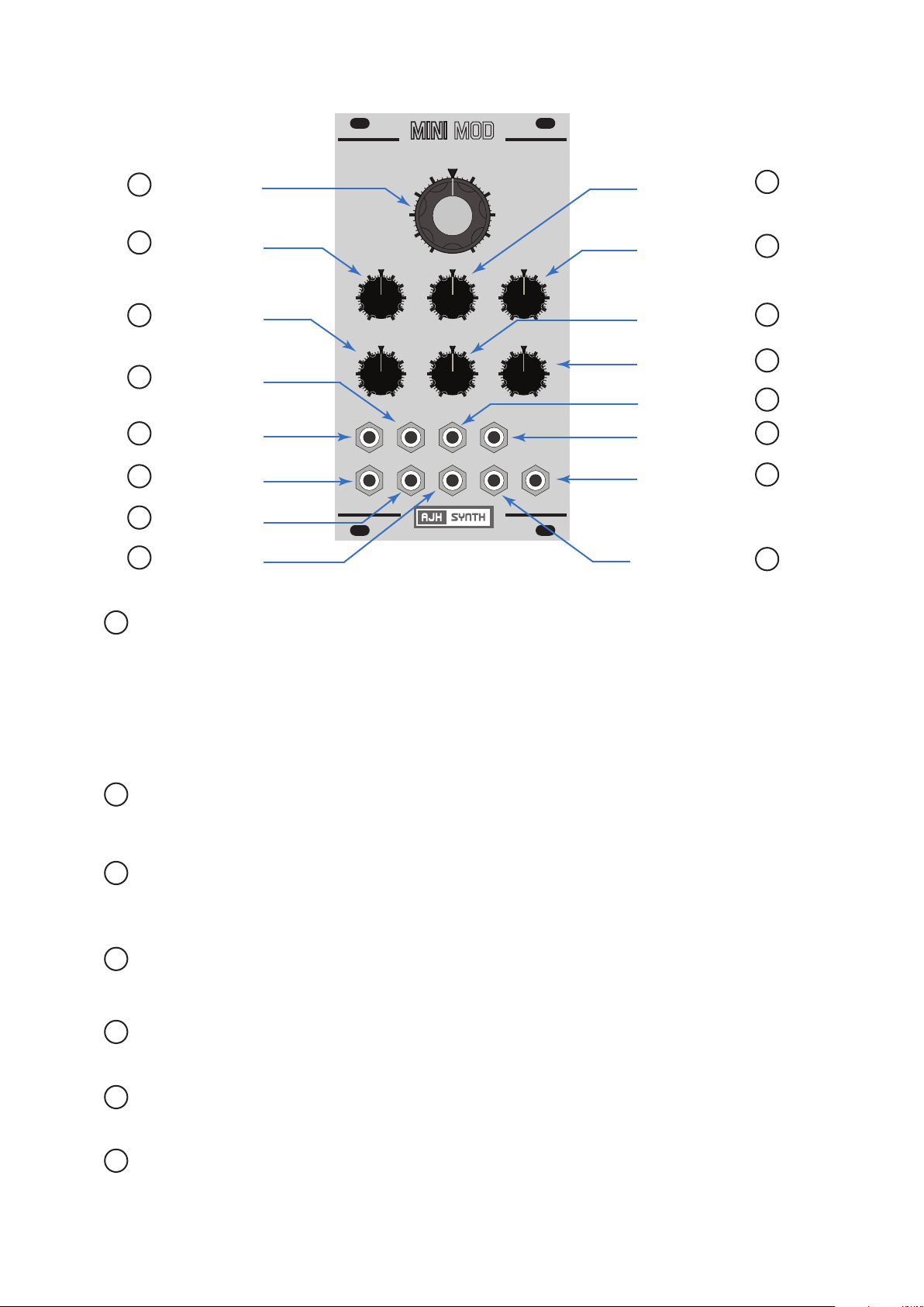
Controls, Inputs and Outputs
7 Cuto Freq.
9 Freq. CV Level
4 Input 1 Level
11 1/3 CV Input
10 1V/Oct Input
8 Freq. CV Input
1 Audio Input 1
2 Audio Input 2
TRANSISTOR LADDER FILTER
FREQ CV EMP CV
4
2
0
INPUT 1
4
2
0
FREQ-CV OUT
FREQ
-2
-4 4
4
6
8
10
6
8
10
6
2
0
10
INPUT 2 INPUT 3
4
6
2
0
10
2/3 CV1V/Oct
IN 2
8
8
EMP-CV1/3 CV
IN 3IN 1
2
EMPHASIS
4
2
0
4
2
0
mod
Emph. CV Level 15
Emphasis Level 13
6
8
10
6
8
10
Input 2 Level 5
Input 3 Level 6
2/3 CV Input 12
Emp. CV Input 14
Audio Output 16
Audio Input 3 3
1 Audio Input 1 :
2 Audio Input 2 :
3 Audio Input 3 :
4 Input 1 Level :
(Audio)
5 Input 2 Level :
(Audio)
Audio Input 1 forms part of a 3 input audio mixer which is attached to the front end of the
lter. This Input is mixed with Input 2 and Input 3 at a level set by Audio 1 Level control
(4). Typically the output from a VCO would be connected to this Input, but any AC signal
with a level of up to +/- 5 Volts is acceptable. .
All three Audio Inputs are for audio signals only, the lter signal path is AC coupled so DC
control voltages are not useful here but will not cause any problem if accidentally
connected.
Audio Input 2 forms part of a 3 input audio mixer which is attached to the front end of the
lter. This input is mixed with Input 1 and Input 3 at a level set by Audio 2 Level control
(5). Signal levels of up to +/- 5 Volts are acceptable.
Audio Input 3 forms part of a 3 input audio mixer which is attached to the front end of the
lter. This input is mixed with Input 1 and Input 2 at a level set by Audio 3 Level control
(6). Signal levels of up to +/- 5 Volts are acceptable.
Sets the amount of signal from Audio Input 1 (between 0% and 100%) that is mixed with
Audio Inputs 2 & 3 and sent to the lter core.
Sets the amount of signal from Audio Input 2 (between 0% and 100%) that is mixed with
Audio Inputs 1 & 3 and sent to the lter core.
6 Input 3 Level :
(Audio)
7 Cuto Freq. :
Sets the amount of signal from Audio Input 3 (between 0% and 100%) that is mixed with
Audio Inputs 1 & 2 and sent to the lter core.
The Cuto Frequency control manually varies the cut o frequency of the low pass
lter. At the minimum setting (fully counter clockwise) the lter will cut o all frequencies
with no audio output and at the maximum setting the lter will pass all frequencies. It is
still active when using CV control, in which case it acts as an oset control.
Page 3

8 Freq CV Input :
Connect an external control voltage to this Input for voltage control of the lter cuto
frequency. The amount of signal passed to the lter core control circuitry can be adjusted
with the Freq. CV Level control (9)
9 Freq. CV Level :
10 1 V/Oct Input :
11 1/3 CV Input :
12 2/3 CV Input :
13 Emphasis Level :
Sets the amount of control voltage (between 0% and 130%) which is sent from the Freq.
CV Input (8) to the lter cuto circuitry. It has a greater range than the 1 V/Oct Input so
that overmodulation eects are possible. 1V / Octave from the Freq. CV Input occurs
with this control knob pointing to position 7 ( 2 o’clock).
A voltage applied to this Input changes the lter cuto at the rate of 1 volt per octave, or
if the lter is in full self oscillation (Emphasis Control fully clockwise) it will control the
pitch of the resulting sine wave at the rate of 1 V/Oct. When compared to the Model D this
emulates having “Keyboard Control” switches 1 and 2 “On”.
A voltage applied to this input changes the lter cuto at the rate of 333 mV per octave.
When compared to the vintage Model D this is the equivalent of having “Keyboard
Control” switch 1 “On” and switch 2 “O”.
A voltage applied to this input changes the lter cuto at the rate of 666 mV per octave.
When compared to the vintage Model D this is the equivalent of having “Keyboard
Control” switch 2 “On” and switch 1 “O”.
This control manually regulates the amount of internal feedback applied to the lter core.
“Emphasis” is now more commonly known as resonance in the modular synth world, they
are just dierent words for the same eect.
At high levels of feedback (between positions 8 and 10) the lter will self-oscillate, so that
even without any audio input to the lter a sine wave output is generated and the
frequency can be controlled by applying control voltages to the 1V/Oct, Exp. CV, 1/3 or
2/3 inputs.
14 Emp CV Input :
15 Emp. CV Level :
16 Audio Output :
E Gain Jumper :
(J1 on PCB)
Like the Model D, when using the 1 V/Oct the sinewave can be played in the same
manner as a VCO with a tracking range of 3 - 4 octaves.
The CV scaling is not temperature corrected so it may drift with changes in ambient
temperature. Under normal circumstances it should track reasonably accurately over a
four octave range. Again, this correctly emulates the behaviour of the vintage Model D
lter.
Applying a control voltage to this Input will vary the Emphasis at the level set by the
Emp. CV Level control (15). Acceptable input voltage range is +/- 5V
This varies the amount of control voltage passed from the Emp. CV Input (14) to the lter
core and it’s range is 0% to 100%. The manual Emphasis Level control (13) is still active
when using external CV control of Emphasis and acts as an oset control.
This is the audio output for the signal after passing through the lter core and would
typically be connected to the Audio Input of a VCA. The output level is dependent upon
the input level, with a single input of +/- 5V to (for example) Audio Input 1 and Audio 2
Level at 100% the gain would be unity, i.e. output would also be +/- 5V.
Removing this jumper increases the gain of the signal by around 70% BEFORE it is fed to
the lter core, which can give a nice overdrive eect. This can be used to emulate the
vintage Model D “trick” of plugging the headphone output back into the VCF External
Input.
With this jumper removed there is a proportionate (70%) increase in VCF output level and
this should be compensated further down the signal chain. So, if being fed into a VCA the
VCA Input Level control will need to be turned down to compensate for this higher signal
level.
Page 4

Note:
This information is given for completeness, the MiniMod VCF is calibrated after manufacture
and under normal circumstances should not require any user adjustment.
A Scale Adjust
B Regen Adjust
C Oset Adjust
D Range Adjust
E Gain Jumper
Adjustment and Calibration
A Scale Adjust :
B Regen Adjust :
C Oset Adjust :
Power Cable
Red Stripe aligns with -12V as shown
Sets the 1V/Oct voltage scaling. To adjust, rst remove all inputs, then turn Emphasis
Level (13) to 10 (full on) and adjust Frequency Control (7) for 440hz output. Now apply
EXACTLY 2V to the 1 V/Oct input and adjust for 1760Hz output (precisely 2 octaves
higher).
With no inputs, set Emphasis Level (13) to 10 (full on) and adjust Frequency Control (7) for
440Hz. Now turn Empahsis Level to 8 and turn Scale Adjust Trimmer until the lter just
starts to selfsoscillate.
Adjusts the vactrol circuit oset. FOR MANUFACTURER ADJUSTMENT ONLY, specialist
test equipment is needed to calibrate this trimmer correctly.
D Range Adjust :
E Gain Jumper :
Sets the frequency range. To adjust remove all Inputs, set Emphasis Level (13) to 10 (full
on) and set Cuto Frequency (7) to -1 position. Adjust trimmer for 440Hz output.
See previous page.
If you need any help using this module or have any technical questions please feel free to
contact us at support@ajhsynth.com
Copyright © AJHSynth 2014
 Loading...