

Page 1

Rev: 1.00
MAINBOARD
User's Manual
* Product Name: PT-694T-A
* All other product names and trademarks or copyrights are belong to their
respective owners.
* Specifications and information contained in this manual are subject to change
without notice.
* Supports AGP 2.0 including 4x AGP
Page 2

INTRODUCTION
Federal Communications Commission
(F.C.C) Statement
This device complies with Part 15 of the FCC Rules. Operation of this
device is subject to the following two conditions: (1) this device may not
cause harmful interference, and (2) this device must accept any interference
received, including interference that may cause undesired operation.
Accessories: This device has been tested and found to comply with the
limits of a Class B digital device, the accessories associated with this
equipment are as follows:
1. Shielded serial cable. (Can be obtained from multiple retail outlets)
2. Shielded printer cable. (Can be obtained from multiple retail outlets)
3. Shielded video cable. (Can be obtained from multiple retail outlets)
4. Shielded power cord. (Provided by manufacturer)
These accessories are required to ensure compliance with FCC Rules.
This equipment has been tested and found to comply with the limits of a
Class B digital device, pursuant to Part 15 of the FCC Rules. These limits
are designed to provide reasonable protection against harmful interference
in a residential installation. This equipment generates, uses and can radiate
radio frequency energy and, if not installed and used in accordance with the
instructions, may cause harmful interference to radio communications.
There is no guarantee that interference will not occur in a particular installation.
If this equipment does cause harmful interference to radio or television reception,
which can be determined by turning the equipment off and on, you are encouraged
to try to correct the interference by one or more of the following measures:
1. Reorient / relocate the receiving antenna.
2. Increase the separation between the equipment and reciver.
3. Connect the equipment into an outlet on a circuit different from that
to which the receiver is connected.
4. Consult the dealer or an experienced radio/TV technician for help.
Caution: Changes or modifications not expressly approved by the
manufacturer could void the user’s authority to operate the equipment.
2
User's Manual
Page 3

INTRODUCTION
Disclaimer
The vendor makes no representations or warranties with respect to the
contents here of and specially disclaims any implied warranties of
merchantability or fitness for any purpose. Further the vendor reserves
the right to revise this publication and to make changes the contents here
of without obligation to notify any party beforehand.
Duplication of this publication, in part or in whole, is not allowed without
first obtaining the vendor’s approval in writing.
Trademarks and Remarks
MS-DOS, Windows, Windows NT, Windows 9x and Windows 2000 are
products of Microsoft Corp, with its ownership of trademark, and are
distributed by the Vendor under a license agreement.
All trademarks used in this manual are the property of their respective
owners.
Canadian D.O.C Statement
This digital apparatus does not exceed the Class B limits for radio noise
emissions from digital apparatus as set out in the radio interference
regulations of the Canadian Department of Communications.
User's Manual
3
Page 4

INTRODUCTION
Table of Contents
PACKAGE CHECKLIST
CHAPTER 1
1. INTRODUCTION OF PT-845DDR-A(AN) MOTHERBOARD................
1.1 Product Description..................................................................................
1.2 Features & Specifications .............................................................................
1.3 Board Level Feature.....................................................................................
1.4 Comprehensive Mainboard View ............................................................
2. HARDWARE INSTALLATION ..........................................................................
2.1 Jumper Setting
2.1 .1 Setting the Jumpers ............................................................................
2.1 .2 Clear CMOS................................................................................................
2.2 Connect ions............................................................................................
2.2.1 Installing the CPU ...................................................................................
2.2.2 Cooling Fan............................................................................................
2.2.3 Installing the Memory Modules (DIMM)........................................................
2.2.4 Floppy Drives......................................................................................
2.2.5 IDE Hard Drivers and CD-ROMs Drives ................................................
2.2.6 Power LED Connections ........................................................................
2.2.7 Power Supply Connector ......................................................................
2.2.8 IrDA-Compliant Infrared Module Connector...........................................
2.2.9 LAN Wake-up Connector..........................................................................
2.2.10 External Connectors.............................................................................
2.2.11 Installing an AGP Card ........................................................................
2.2.12 Installing an AMR Card ........................................................................
3. MAINBOARD BIOS SETUP................................................................................
3.1 About the BIOS .......................................................................................
3.2 Main Menu ...............................................................................................
3.3 Standard CMOS Features .....................................................................
.............................................................................................
7
7
8
9
11
12
12
12
13
14
14
15
15
16
16
17
18
18
19
20
22
22
23
23
25
26
4
User's Manual
Page 5

INTRODUCTION
3.4 Advance d BIOS Features ...........................................................................
3.5 Advance d Chipset Features ..................................................................
3.6 Integrated Peripherals ............................................................................
3.7 PC Health Status ....................................................................................
3.8 Power Management Setup .........................................................................
3.9 PnP/PCI Configurations .............................................................................
3.10 Frequency / Voltage Control ......................................................................
3.11 Load Fail-Safe Defaults ...........................................................................
3.12 Load Optimize Defaults............................................................................
3.13 Supervisor Password and User Password Setting.....................................
3.14 Save & Exit Setup / Exit Without Saving ............................................
3.15 PCI Device Listing ......................................................................................
30
33
36
40
42
45
47
48
48
48
49
50
4. FLASH BIOS PROGRAMMING UTILITY............................................................
5. DMI UTILITY................................................................................................................
6. INSTANTLY AVAILABLE PC......................................................................................
6.1 What is an Instantly Available PC? .......................................................
6.2 Core Technology Suspend to RAM (S3) ................................................
6.3 The Key Ingredients ......................................................................................
6.4 Installation ..............................................................................................
6.5 Using Suspend t o RAM.............................................................................
6.6 Related Documents ........................................................................................
7. SOFTWARE INSTALLATION.....................................................................................
7.1 Please Select Model Name.......................................................................
7.2 Install 845 Drivers..........................................................................................
7.3 Install Sound Drivers........................................................................................
7.4 Other Driver Search........................................................................................
8. Appendix..........................................................................................................................
8.1 Update Your system
BIOS...............................................................................
51
52
53
53
53
54
55
56
56
57
57
58
62
63
64
64
User's Manual
5
Page 6
INTRODUCTION
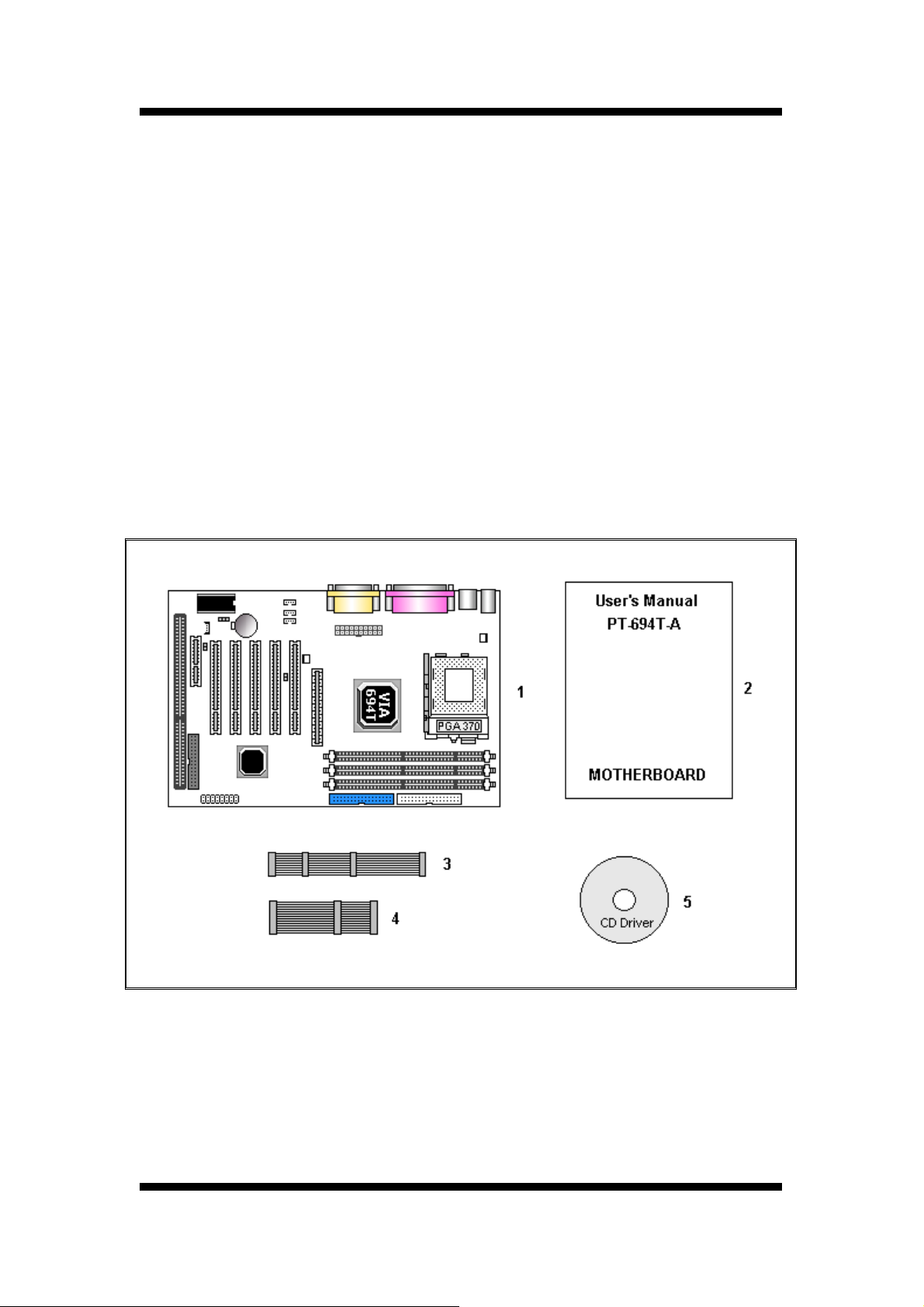
Package Checklist
Your mainboard package should include the items listed below. Damaged or missing items
should be reported to your vendor.
1. One mainboard
2. One User’s Manual
3. Floppy disk ribbon cable for 3.5” floppy drive
4. 80 pin IDE ribbon cable for internal ATA100 or ATA66 IDE drive
(Note: The 80pin ribbon cable is designed with a 40pin connector.)
5. Support CD-ROM containing the following support software:
(The latest drivers can always be found at their respective web sites.)
Support software for updating the Flash BIOS
6
User's Manual
Page 7

INTRODUCTION
1. INTRODUCTION
1.1 Product Description
T
today. Designed as a flexible, high-performance and cost-effective solution for System
Integrators and End Users alike, this mainboard provides the power and expandability to meet
the requirements of the most advanced operating systems and software applications.
This mainboard is a high performance Pentium based (FSB 400MHz) system.
Advanced hardware designs include ACPI's
Instantly Available PCs. Also, by incorporating
DMA/100 Bus Mastering IDE
system performance is assured and system design and implementation is simplified.
Fully Plug & Play compatible via an Award BIOS, this mainboard facilitates easy system
configuration and peripheral setup. Advanced BIOS features include
Monitoring and Alert functions.
compatible with PC98 specification. This mainboard is the ideal foundation for high-end
his mainboard represents the highest level of technology available in PC Mainboards
Suspend to RAM for the implementation of
CNR, 4X AGP
and
Universal Serial Bus (USB)
The Award BIOS also supports
, AC97,
Super I/O, Ultra
onto the mainboard, optimum
Intelligent Hardware
readiness and is
ACPI
computer systems.
User's Manual
7
Page 8

INTRODUCTION
1.2 Specification
Supports Intel® FC-PGA / FC-PGA2 Pentium® III & Celeron
Processor
Chipset
BIOS
System
Memory
On-board I/O
Features
(Copper Mine /Tualatin) or other compatible processors
Supports 370 FCPGA2 Pentium® III
VIA® VT82C694T (Apollo Pro 133T) Chipset
VIA® VT82C686B South Bridge
Award PCI BIOS, support ACPI, DMI, Plug-and-Play, Boot from
CD-ROM, SCSI, LS-120, and ZIP devices, Anti-virus BIOS to prevent
boot virus
3 x 164 pin SDR DIMMs to support up to 1.5GB DDR SDRAM
ECC DIMM support
1 x Floppy Port (Up to 2.88MB)
1 x Parallel Port (Support EPP and ECP)
2 x Serial Ports (16550 Fast UART Compatible)
2 x USB Ports
2 x USB Header (for 2 additional USB ports on front/side panel)
1 x MIDI/game port
Advanced
Features
Master IDE
Expansion
Slots
ATX Power
Connector
1 x Audio jacks: Line-out, Line-in and MIC-In
2 x Ir DA TX/RX Header
Supports 4x AGP data transfer and 4x Fast
AC97 Audio on board
Suspend to RAM support
AMR modem upgrade
Modem Ring-in Remote Power on
Wake up on LAN
Keyboard Power On
Hardware Monitoring function
2 x UltraDMA/100 IDE Ports support up to 100 MB/Sec.
ONE AMR SLOT 32-bit AGP slot, Five 32-bit PCI Bus Master slots
3V, 5V and 12V 20-Pin
ATX Power connector
8
User's Manual
Page 9
INTRODUCTION
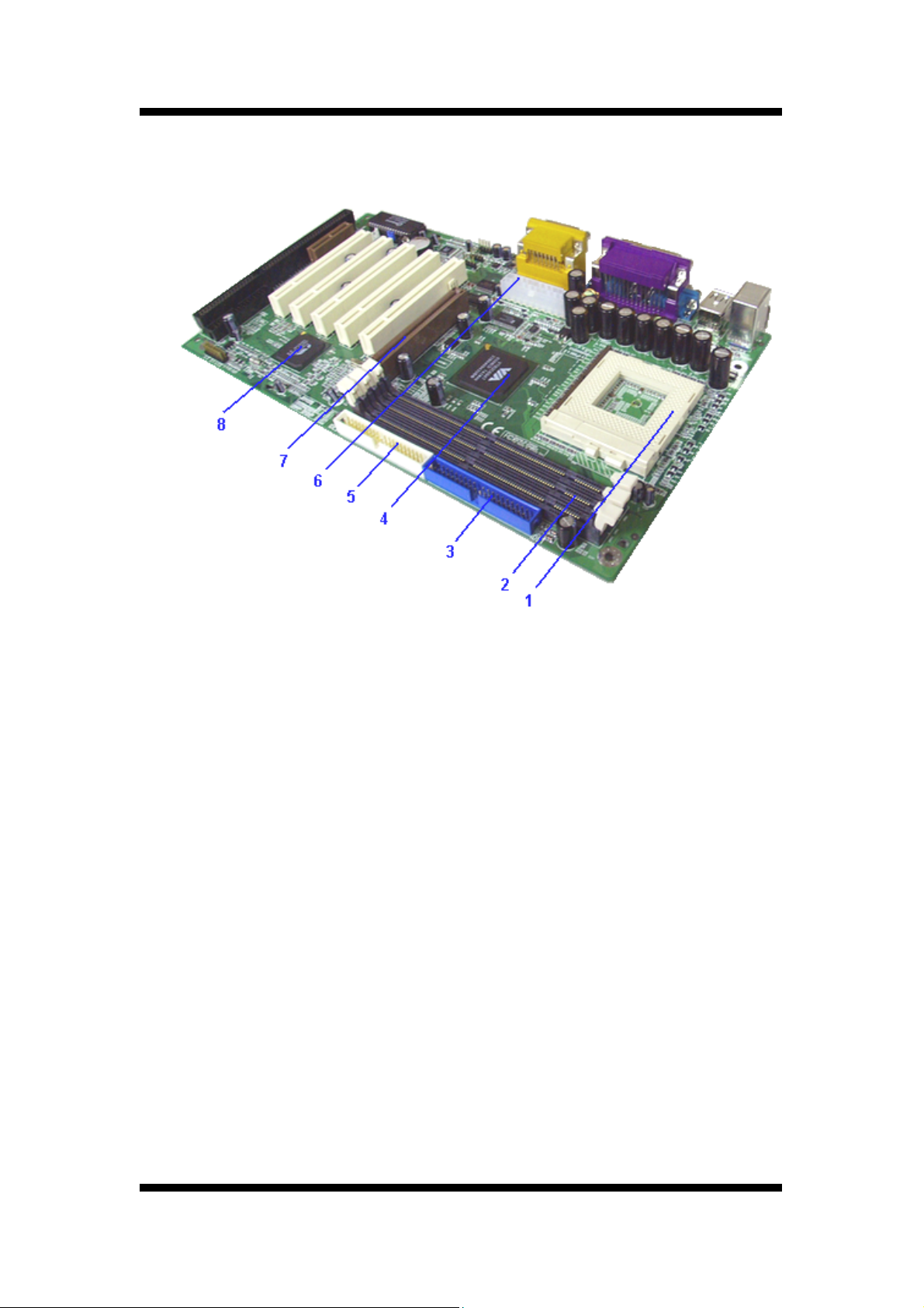
1.3 Board Level Feature
1. CPU Socket:
2. DDR DIMM Sockets: Two 164-pin DIMM Sockets support up to 1.5GB.
3. IDE1 connector: Connector for first IDE channel.
4. North bridge controller: VIA 82C694T and memory controller Hub.
5. IDE2 connector: Connector for second IDE channel.
6. ATX power connector: 20-Pin ATX Power Connector.
7. AGP Slot:
8. South bridge controller:
ZIF Socket 370 for Intel Pentium III CPU.
Accelerated Graphics Port (AGP).
VIA 82C686B I/O Controller Hub.
User's Manual
9
Page 10
INTRODUCTION
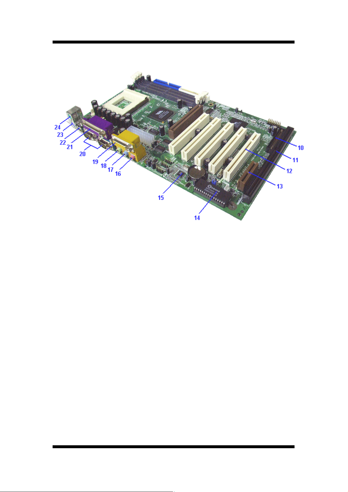
10. Floppy disk connector: Built-in Floppy controller supports (2) 5.25" or 3.5" Floppy drives.
11. ISA Slot: 16-bit ISA Slot.
12. PCI Slots:
13. AMR Slot:
14. BIOS: Award Plug & Play Bios.
15. Audio CODEC
16. Microphone jack:
17. Line in jack:
18. Line Out jack: This Line Out (lime) jack connects a headphone or a speaker.
19. MIDI/Game Port: 15-pin female MIDI/Joystick connector.
20. Serial Port:
21. Parallel Port: EPP and ECP compatible 25-pin D-Sub parallel port.
22. USB Ports:
23. PS/2 Keyboard Port: Supports PS/2 style keyboards.
24. PS/2 Mouse Port: Supports PS/2 style mice.
Five 32-bit PCI Slots are provided.
The Audio Modem Riser is a cost-effective AMR AC97/MC97.
: Three 1/8 female jacks for Line Out, Line In and MIC
This MIC (pink) jack connects a microphone.
This Line In (light blue) jack connects a tape player or other audio sources.
Two 9-pin COM1/COM2 ports.
Two 4-pin USB Connectors.
10
User's Manual
Page 11
INTRODUCTION
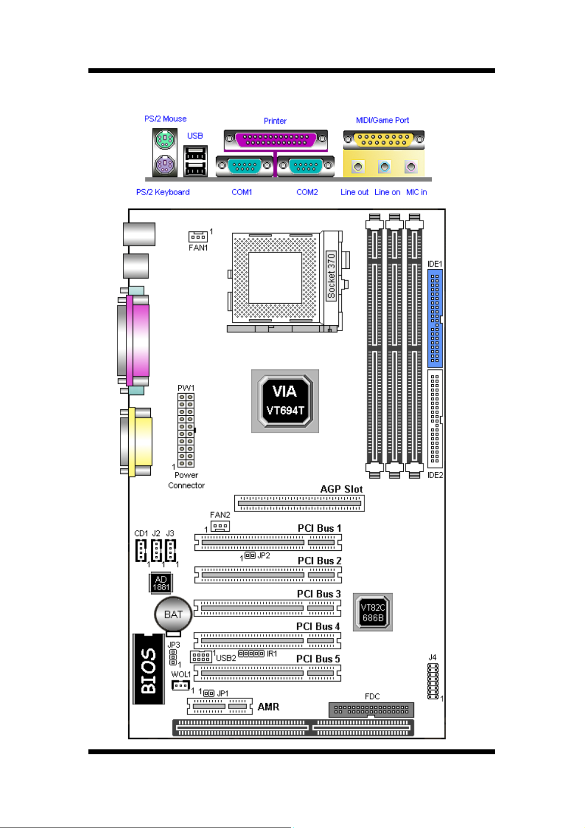
1.4 Comprehensive Mainboard View
User's Manual
11
Page 12
HAREWARE INSTALLATION
2. Hardware Installation
2.1 Jumpers Setting
Static Precautions
Static electricity can be a serious danger to the electronic components on
this mainboard. To avoid damage caused by electrostatic discharge,
observe the following precautions:
■ Don't remove the mainboard from its anti-static packaging until
you are ready to install it into a computer case. Also, handle add-in
cards and modules by the edges or mounting bracket.
□ Before you handle the mainboard in any way, touch a grounded,
anti-static surface, such as an unpainted portion of the system
chassis, for a few seconds to discharge any built-up static
electricity.
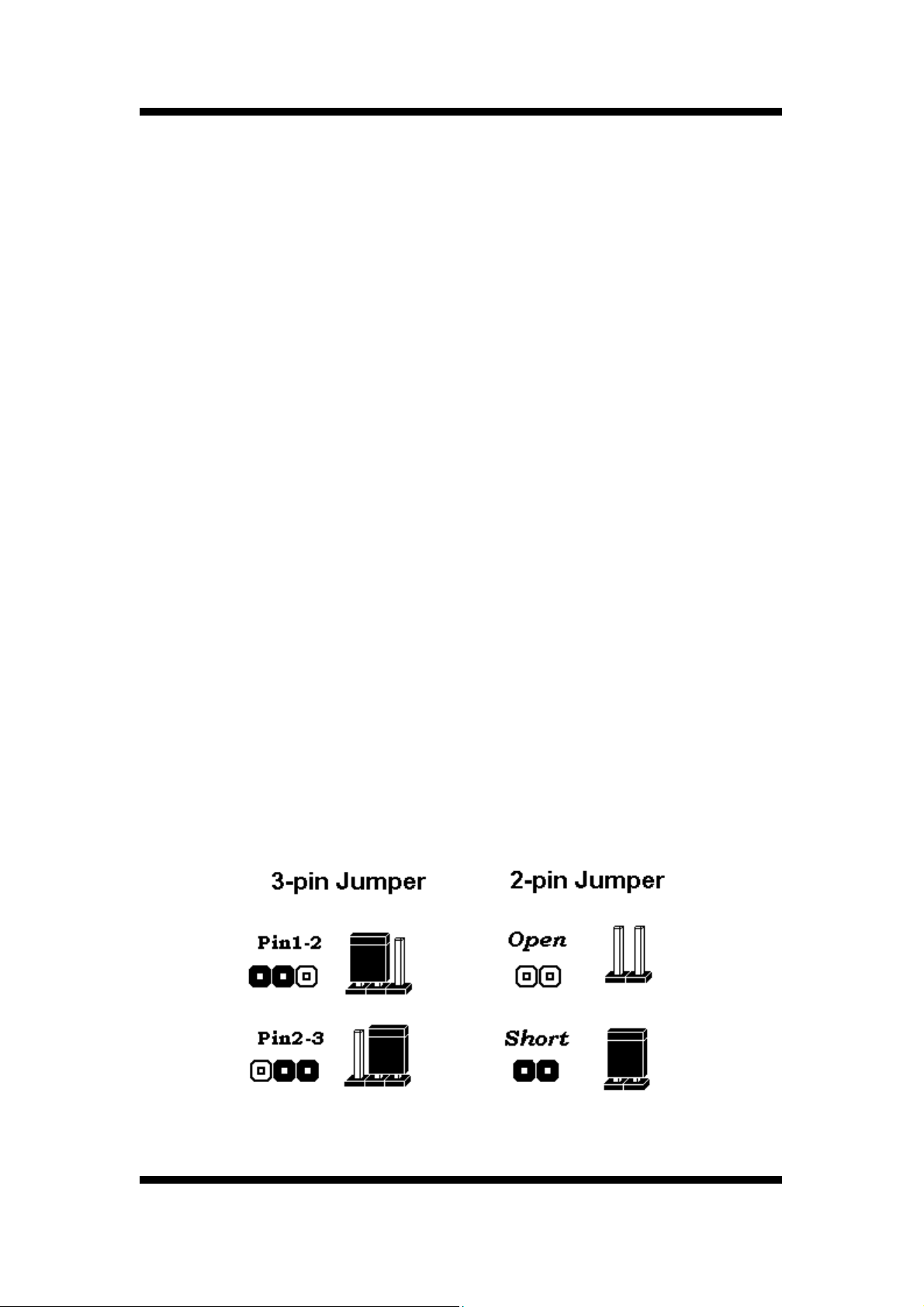
2.1.1 Setting the Jumpers
Jumpers are used on this mainboard to select various settings and features. A 2-pin
jumper has two settings: Open and Short (or Closed). The jumper is closed by placing
the Jumper Cap across the two pins, thereby connecting them. 3-pin jumpers can be
set to pins 1-2 or 2-3 connected. Pin-1 is labeled on the circuit board.
12
User’s Manual
Page 13
HAREWARE INSTALLATION
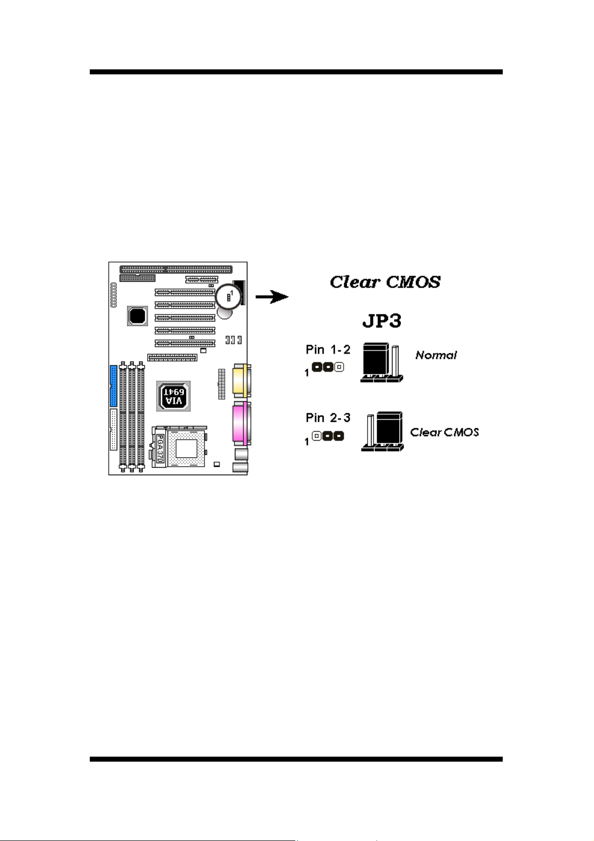
2.1.2 Clear CMOS (JP7)
If you have set the password ,either to protect the BIOS configuration or to restrict access to
the computer, the pssword is stored in CMOS RAM. If you forget the password, the CMOS can
be cleared by setting this jumper to Clear CMOS. Also in case there is a CMOS error or
improper CPU setting through the mainboard's BIOS that causes boot failure, the CMOS must
cleared by setting this jumper to Clear CMOS to allow the system to boot.
Clearing the CMOS will clear all user-defined BIOS setup options.
User’s Manual
13
Page 14
HAREWARE INSTALLATION
2.2 Connections
2.2.1 Installing the CPU
> WARNING: Use of a CPU Cooling Fan is required to prevent CPU from overheating.
The Fan should be installed first before inserting the CPU into its socket.
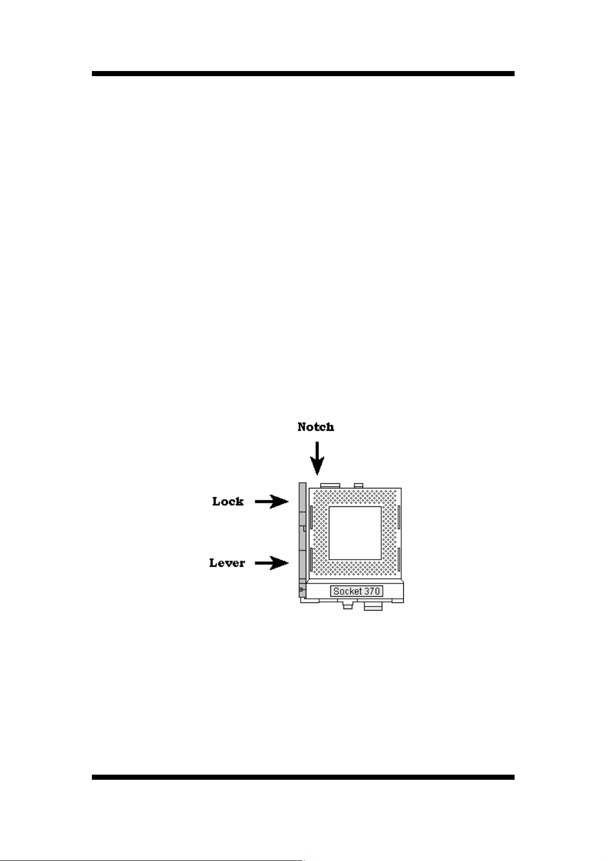
> Locate the ZIF(Zero Insertion Force) Socket 370.
> First open the socket by pulling the lever sideways, then upwards. Notice how the
lever locks in place when pressed all the way down.
> The CPU must be inserted with the correct orientation. One corner of the CPU has a
Notch and looks different that the other three. This corner is also missing a pin unlike
the other three.
Align this corner towards the end of the lever as shown in the figure at right. Insert the
CPU, press it down.
> Close the lever until it locks into place.
14
User’s Manual
Page 15
HAREWARE INSTALLATION
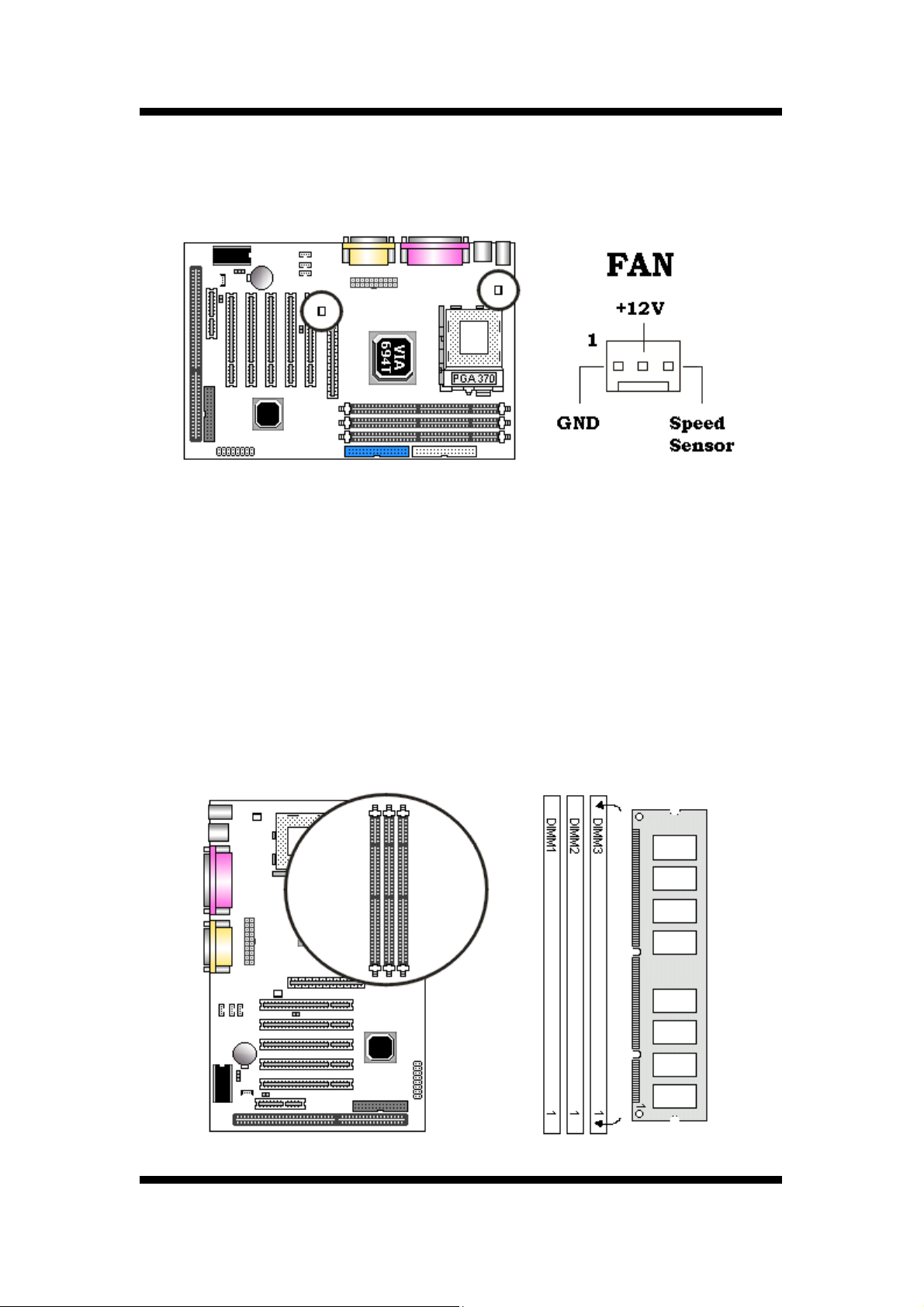
2.2.2 Cooling Fan
These are small3-pin Header Connectors that provide12-Volt power for CPUand chassis
cooling fans. Plugin the fan cable to the connector.
2.2.3 Installing the Memory Modules (DIMM)
This mainboard has three sockets available for
■
be 3.3 volt Unbuffered Synchronous DRAMs (SDRAM).
DIMM Sizes supported: 8MB, 16MB, 32MB, 64MB, 128MB and 256MB
■
A total of 3 DIMMs can be installed for a maximum RAM capacity of
■
To insert the DIMMs, the modules must be oriented in the correct way. Notice the notches of
168-pin DIMMs. They must
1.5GB
.
the DIMM. Align these notches as shown in the diagram below.
Gently push the DIMM until the retainers on both sides of the socket lock the module in place.
To remove a DIMM, push the retainers outwards to release the module then pull the module
out of the socket.
User’s Manual
15
Page 16
HAREWARE INSTALLATION
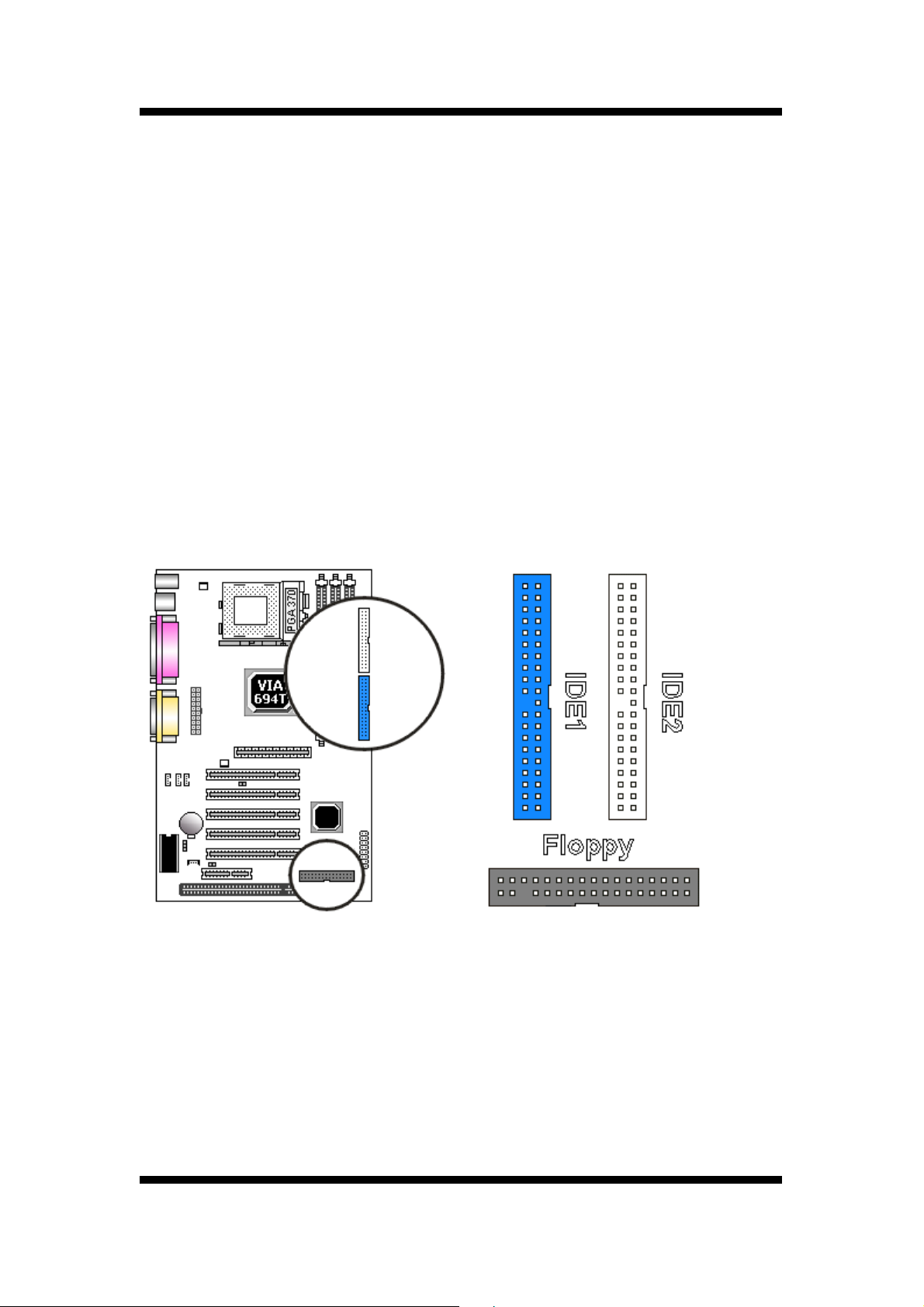
2.2.4 Floppy Drives
The on-board floppy controller supports (2) floppy disk drives with the floppy ribbon cable
provided.
Note: Make sure the RED stripe on the ribbon cable is oriented towards Pin-1.
2.2.5 IDE Hard Drives and CD-ROMs
The on-board Enhanced IDE controller can support up to (4) IDE hard drives or other ATAPI
devices, such as CD-ROMs. This controller, as with all Enhanced IDE controllers, consists of
both Primary and Secondary ports. Each port has an associated connector and cable which can
support up to (2) ATAPI devices each.
Note:Make sure to align the RED stripe on the ribbon cable with Pin-1 on the mainboard
IDE connector. On most hard drives and CD-ROMs, the RED stripe should be
oriented towards the power connector of the device .F
16
User’s Manual
Page 17
HAREWARE INSTALLATION
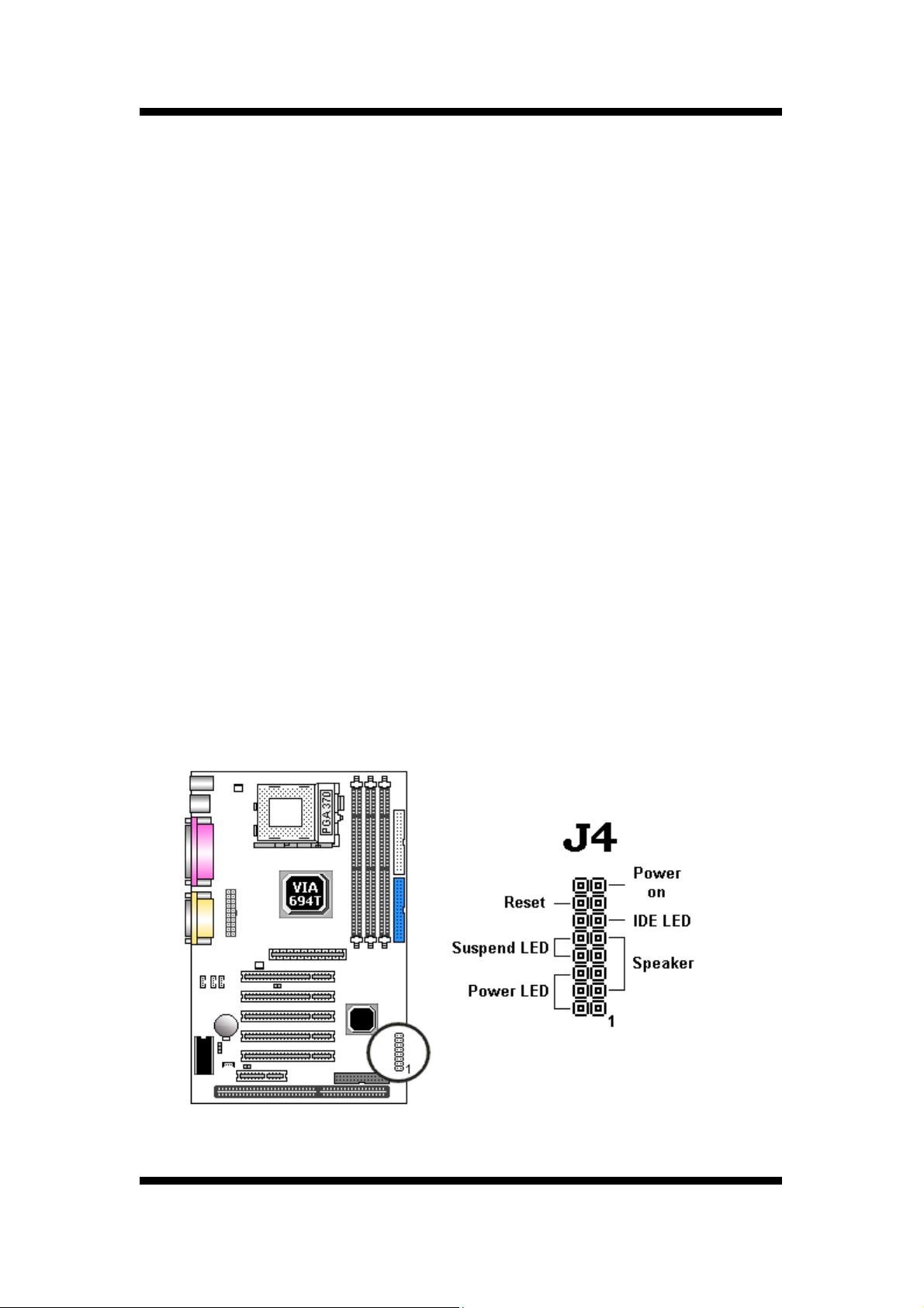
2.2.6 Power LED Connections
System Function Connector Block (J6)
Pins [2 & 4 & 6] Power LED lead
Pins 2 & 4 connect to the power LED from the system's case.
Pins [3 & 5 & 7 & 9] Speaker
Connects to the Speaker lead from the systems case.
Pins [8 & 10] Suspend LED lead
This LED blinks to indicate the system is in suspend mode.
Pins [11 & 12] IDE Activity LED
Hook the IDELED lead to this connector, with the RED lead corresponding to Pin-1.
Pins [13 & 14] Reset switch lead
Connects to the Reset Switch lead from the system's case. The reset switch is used to
cold-boot the system without actually turning off the power, reducing wear and tear on
the power supply.
Pins [15 & 16] Soft Power Switch
Connects to the Power Switch featured on ATX case designs. This switch must be
hooked up before the system can be powered on.
Note: Under the following two conditions, you have to press and hold the switch for
longer than4 seconds to power off your system, regardless of the Soft-Off by
PWRBTN setting in the BIOS.
■ Shortly after the system is powered on, when the BIOS message is not yet appear.
■ When CPU hangs.
User’s Manual
17
Page 18
HAREWARE INSTALLATION
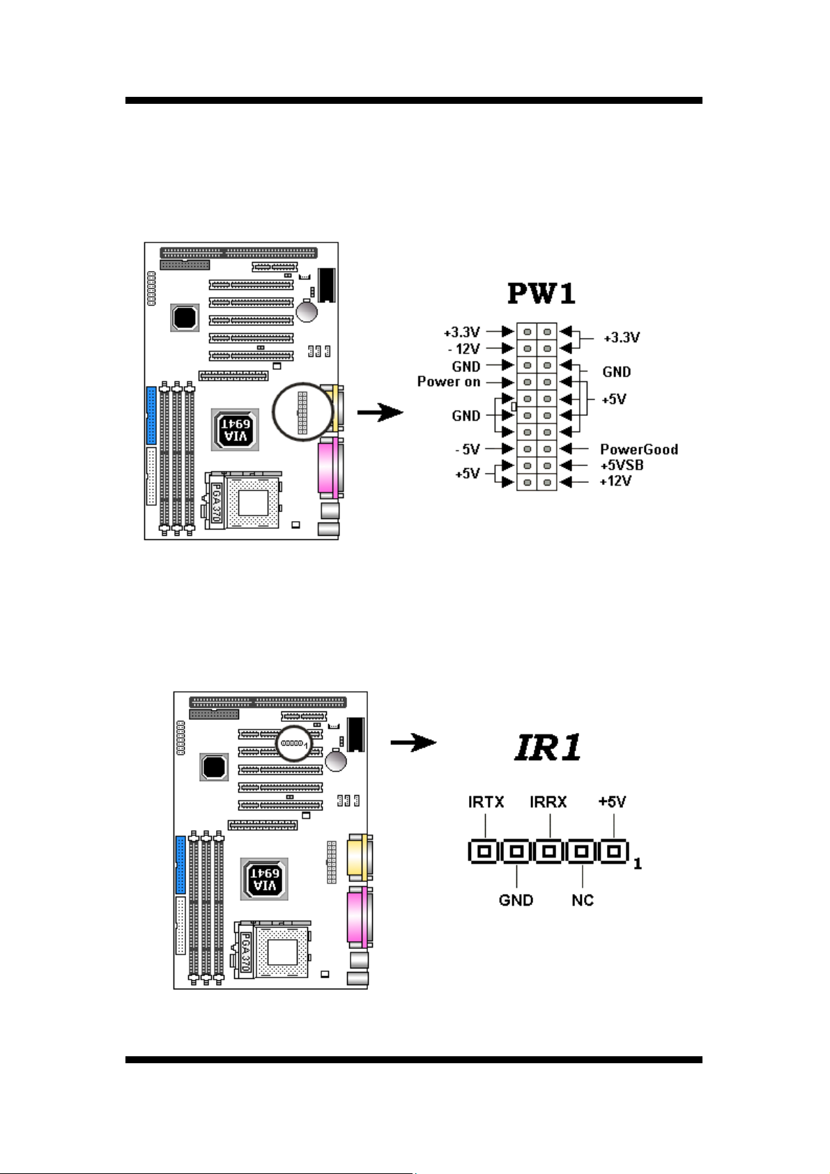
2.2.7 Power Supply Connector
The ATX-style Power Supply Connector is key edto prevent connection in the wrong direction.
Line up the locking mechanismon the connectorfrom the Power Supply with the tab on the
mainboard connector. Press down until the two connectors are locked.
2.2.8 IrDA-Compliant Infrared Module Connector (IR1,IR2)
The IrDA connector bracket hooks directly to this connector on the mainboard. This connector
provides support for the optional wireless transmitting and receiving infrared module. You must
first configure through the BIOS setup where UART2 is directed, COM2or IrDA.
18
User’s Manual
Page 19
HAREWARE INSTALLATION
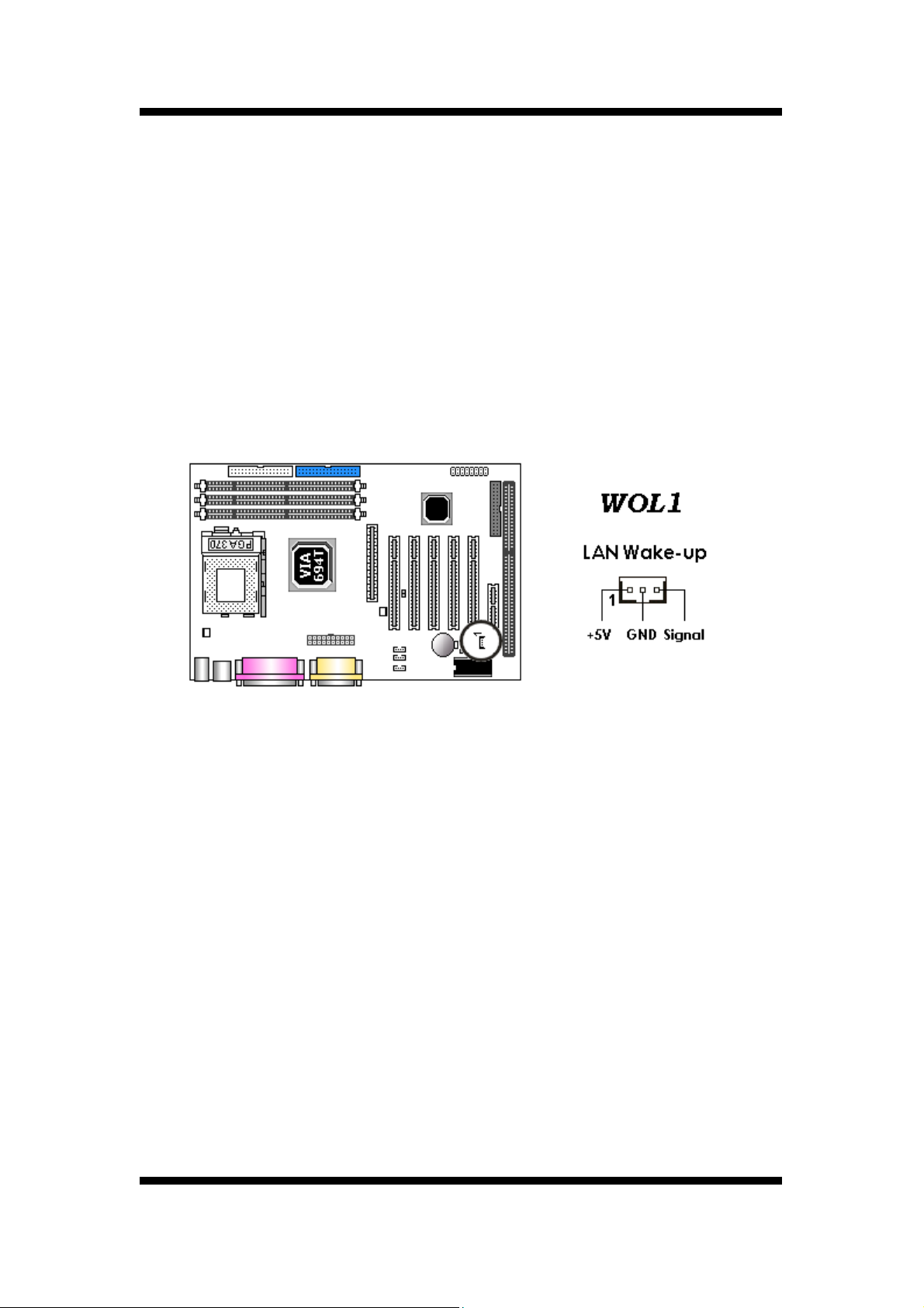
2.2.9 LAN Wake-up Connector (Lan1)
The LAN Wake-up function will allow the network to wake up a Soft Power Down (Soft-Off) PC.
However , if your system is in the Suspend mode , you can wake-up the system only through
an IRQ or DMA interrupt. To use the LAN Wake-up function, you must enable the Wake Up
On LAN/Ring field (under Wake Up Events) in the Power Management Setup of the Award
BIOS. Connect the cable that comes with your LAN card to this connector on the system
board.
Refer to the add-in card's manual for details.
Your LAN card must support Magic Packet in order to use the LAN Wake-up function.
Note:
User’s Manual
19
Page 20
HAREWARE INSTALLATION
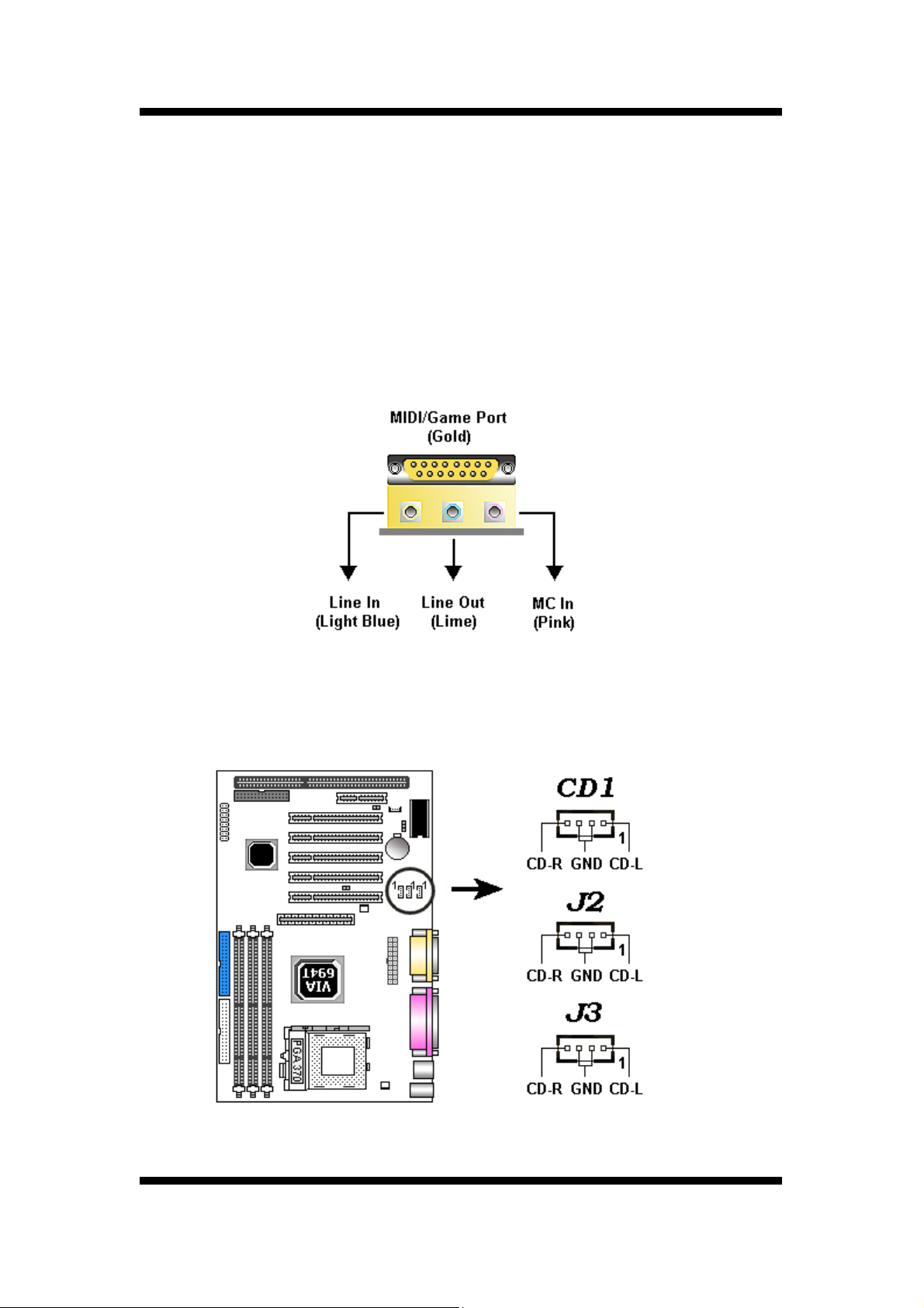
2.2.10 External Connectors
MIDI/Game Port (Optional)
You may plug a joystick or game pad to this (Gold color) 15-pin female connector for game
playing, or connect a MIDI device for playing or editing audio.
Audio Port (Optional)
You can connect powered speakers or headphones to (Lime color) Line Out jack. Cassette
players or other external audio sources can be connected to ( Light Blue color) Line In jack.
Plug in your microphones to (Pink color) MIC jack.
Audio Connectors (CD1,CD2)
This CD Audio connector is available for connecting the CD-ROM drive using CD audio cable.
20
User’s Manual
Page 21
HAREWARE INSTALLATION
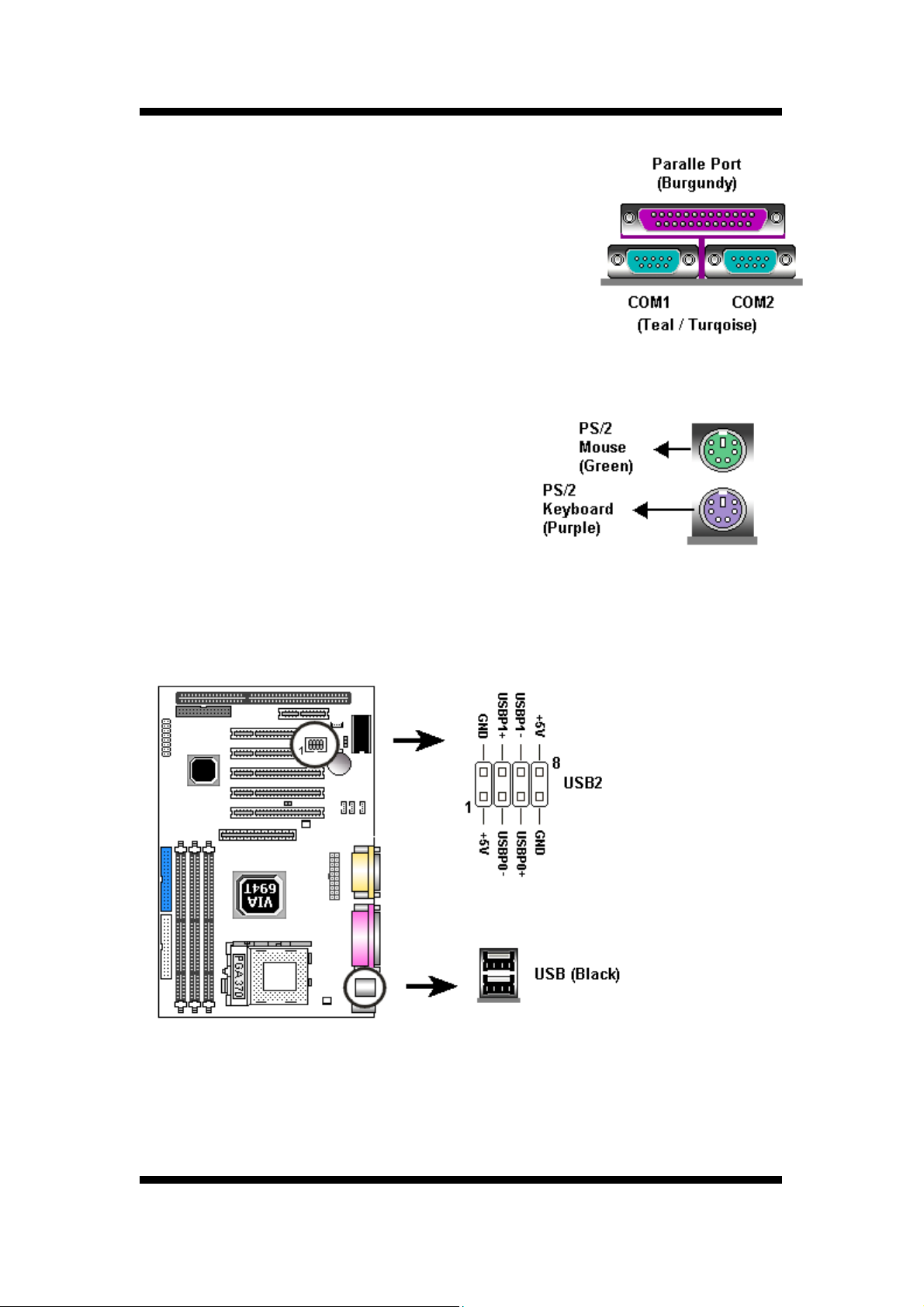
Serial and Parallel Ports
A (Burgundy color) 25-pin D-Sub header is provided
on the back panel for a multi-mode bi-directional parallel port.
Two (Teal/Turquoise color) 9-pin D-Sub headers are also
provided on the back panel for Serial ports.
PS/2 Keyboard and Mouse Connectors
These two connectors (Green color) PS/2 Mouse and
(Purple color) PS/2 Keyboard are located on the
back panel of the mainboard.
USB Connectors
This mainborad supports (Black color) 4 USB devices.
The Cable from the USB
connector bracket hooks to
the USB header on the
mainboard.
These two connectors
permit connection of two
USB peripheral devices
directly to the system.
User’s Manual
21
Page 22
HAREWARE INSTALLATION
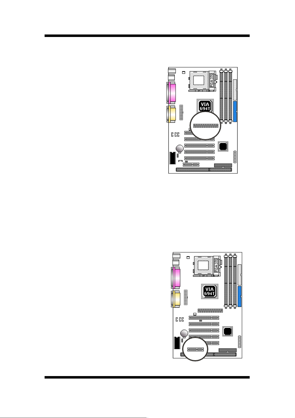
2.2.11 Installing an AGP Card
The main board provides an AGP slot to support 2Xor 4X AGP set with model shipped with the
package.
Note:
The main board with VIA
AGP set (North Bridge)
VT694T is support up to
4X AGP set.
2.2.12 Installing an AMR Card
One AMR (Audio/Modem Riser) standard interfaceconnector is supports Audio Codec 97
(AC97) and/or Modem Codec97 (MC97) cards. This provides an upgreadeable audio and/or
modem solution at an increbibly low cost. There are two type of AMR, one defined as primary
and another defined assecondary. This mainboard uses as primary channel so, a secondary
AMR can coexit without the need to disable the onboard CODEC. The mainboard's onboard
CODEC must be disable when using the primary AMR.
Note:
If your audio function is coming from
the CNR card instead of the onboard
audio feature, set AC97/MC97 Mode
jumper block properly (Refer to page
13). Also make sure the AC97 Audio
option is set to Auto (default) in
Advanced Chipset Features of the
BIOS.
22
User’s Manual
Page 23

MAINBOARD BIOS SETUP
3. MAINBOARD BIOS SETUP
3.1 About the BIOS
The Mainboard BIOS (Basic Input/Output System) acts as the bridge between your Hardware
(CPU, Disk Drives, Video, etc.) and Operating System Software (Windows 95, OS/2 and so
on ) The BIOS Setup (also called CMOS Setup) is where many hardware configuration options
are set and stored. This configuration information will remain in the BIOS until it is changed, or
cleared by removing the battery for a while then reinstalling it back or by setting the Clear
CMOS jumper if there is one.
CMOS (Complementary Metal Oxide Semiconductor) refers to the chip in which the BIOS
information is stored. This mainboard features Award BIOS, which provides an easy to use
Setup program to aid in hardware configuration. In this section we will look at the various
menus and options contained in the Award BIOS Setup Program. This mainboard also
features a Flash BIOS. A Flash BIOS can be upgraded via
software, thereby eliminating the need to actually replace the BIOS Chip on the mainboard.
Procedures for updating the BIOS follow this section. The Award BIOS installed in your
computer system's ROM (Read Only Memory) is a custom version of an industry standard
BIOS. This means that it supports Intel processor in a standard IBM-AT compatible
input/output system.
☆ Using Setup
In general, you use the arrow keys to highlight items, <Enter> to select or display the possible
selections, <Page Up> and <Page Down> keys to change entries, <F1> for general help and
<Esc> to quit.
An item marked with a indicates that there is a submenu for this item. A gray-out item marked
with an x indicates that the item is not available. The item may be associated with another item
and its availability is dependent on that associated item. Gray-out items are for information
display only and contain no selectable fields.
User’s Manual
23
Page 24

MAINBOARD BIOS SETUP
☆ Getting Help
Pressing <F1> will display a help window that describes the appropriate keys to use. Pressing
<Enter> will display a small help window that describes the possible selections for the
highlighted item. To exit the Help Window press<Esc>.
A brief description of some highlighted selection may appear at the right frame (titled Item Help)
of the setup screen.
☆ A Final Note about Setup
Not all systems have the same Setup. While the basic look and function of the Setup program
remains the same for all systems, individual motherboard and chipset combinations require
custom configurations. For example, you may find that your Setup main menu has a different
number of entries from the main menu displayed in this manual. These are simply features not
supported (or not user configurable) on your system. The final appearance of the Setup
program also depends on the Original Equipment Manufacturer (OEM) who built your system.
If your OEM has decided that certain items should only be available to their technicians, those
items may very well be removed from the Setup program.
24
User’s Manual
Page 25

MAINBOARD BIOS SETUP
3.2 Main Menu
Shortly after the system is powered on, provided a CPU and sufficient RAM are installed, you
will see the message:
Press DEL to enter SETUP
.Press the DEL key to enter the Award BIOS Setup program.
Once you enter the Award BIOS CMOS Setup Utility, the Main Menu will appear on the screen.
The Main Menu allows you to select from several setup functions and two exit choices. Use the
arrow keys to select among the items and press <Enter> to accept and enter the sub-menu.
CMOS Setup Utility Main Screen
CMOS Setup Utility - Copyright ( C ) 1984 - 1999 Award Software
> Standard CMOS Features
> Advanced BIOS Features
> Advanced Chipset Features
> Integrated Peripherals
> Power Management Setup
> PnP / PCI Configurations
> PC Health Status
Esc: Quit F9:Menu in BIOS
F10: Save & Exit Setup
Time, Date, Hard Disk Type...
Note that a brief description of each highlighted selection appears at the bottom of the screen.
> Frequency/Voltage Control
Load Fail-Safe Defaults
Load Optimized Defaults
Set Supervisor Password
Set User Password
Save & Exit Setup
Exit Without Saving
↑ ↓ → ← : Select Item
User’s Manual
25
Page 26

MAINBOARD BIOS SETUP
3.3 Standard CMOS Features
This first menu is where the most basic hardware options are set. Information regarding the
system clock, IDE hard disks and floppy drives is stored and configured in this section.
To enter the Standard CMOS Features setup screen, press the [ENTER] key with this menu
highlighted. Upon entering the Standard CMOS Setup screen, you will see a screen like that
below:
Standard CMOS Features Screen
CMOS Setup Utility - Copyright ( C ) 1984 - 1999 Award Software
Time ( hh : mm: ss )
>IDE Primary Master
>IDE Primary Slave
>IDE Secondary Master
>IDE Secondary Slave
Drive A
Drive B
Video
Halt On
Base Memory
Extended Memory
Total Memory
Standard CMOS Features
Fri, Jan 1 1999 Item Help Date ( mm : dd : yy )
1 : 28 : 42
Press Enter 4403 MB
Press Enter None
Press Enter None
Press Enter None
1.44M, 3.5 in.
None
EGA/VGA
All Errors
640K
130048K
131072K
Menu Level >
↑ ↓ → ←: Move Enter: Select +/-/PU/PD: Value F10: Save ESC: Exit
F1: General Help F5: Previous Value F6: Fail-Safe Defaults F7: Optimized Defaults
☆ Date and Time
Use the arrow keys to move to and highlight the Date option. Select the Month by using the
<Page Down> and <Page Up> keys. This is how most settings will be configured. Then, move
to the day, year and time via the arrow keys to finish setting the system date and time.
26
User’s Manual
Page 27

MAINBOARD BIOS SETUP
IDE Primary Master, IDE Primary Slave, IDE Secondary Master, IDE Secondary
CMOS Setup Utility - Copyright ( C ) 1984 - 1999 Award Software
IDE Primary Master
IDE HDD Auto-Detection Press Enter Item Help
IDE Primary Master Auto
Access Mode Auto To auto-detect the
Capacity 4312 MB This channel
Cylinder 8912
Head 15
Precomp 0
Landing Zone 8911
Sector 63
Menu Level >
HDD's size, head… on
↑ ↓ → ←: Move Enter : Select +/-/PU/PD : Value F10 : Save ESC : Exit
F1 : General Help F5 : Previous Value F6 : Fail-Safe Defaults F7 : Optimized Defaults
☆ Slave
These four options relate to the (4) IDE hard drives, CD-ROMs or other ATAPI devices that
can be controlled via the on-board IDE controller (review IDE Hard Drives and CD-ROMs in
the Installation Guide). The IDE Primary Master setting specifies the first device on the primary
IDE channel, IDE Primary Slave - the second. IDE Secondary Master and IDE Secondary
Slave specify the devices on the secondary channel.
Pressing <Enter> at each of the four selections brings up a submenu such as one shown
below:
☆ IDE HDD Auto-Detection
Automatically detects and configures hard disk parameters. The Award BIOS includes this
ability in the event you are uncertain of your hard disk's parameters.
User’s Manual
27
Page 28

MAINBOARD BIOS SETUP
☆ IDE Primary/Secondary Master/Slave
This is where you will specify the type of device and how it is represented in the BIOS Setup. If
the device is a hard disk or CD-ROM, generally the Auto option is the best choice for fast and
easy setup of the hard disk parameters. Let's take a look at the difference between the Auto
and Manual options:
Auto
This option instructs the BIOS to automatically configure the hard disk by reading the
parameters (cylinders, sectors, etc.) directly from the hard disk's firmware. Use this
option if you are configuring a new hard drive, or one that has already been formatted
using the Auto option. Keep in mind that a hard drive is configured using a certain set
of parameters, those same parameters must be used for the life of the drive, unless
the drive is re-fdisked using a different parameter set. (This procedure deletes the old
partition(s) on the drive and creates a new one, using the new parameters).
Manual
☆ Access Mode
• One of Enhanced IDE's most important features is LBA (Logical Block Addressing) Mode.
This option allows you to manually enter in the parameters (cylinder, head, precomp,
landing zone and sector) of the hard drive. Generally, this option would be used only
if the hard drive has already been formatted with a certain set of parameters, and
assured consistency between the old and new parameters is desired.
This feature allows the use of larger hard drives by providing a way to bypass the cylinder
limitations imposed by many Operating Systems. LBA Mode is used to extend a hard drive's
useable capacity by remapping the cylinders in a way that is acceptable to these operating
systems. For instance, a hard drive with the parameters of 2100 Cylinders, 16 Heads and 63
Sectors would be represented by LBA Mode as 525 Cylinders, 64 Heads and 63 Sectors.
(Notice that the Cylinders have been divided, and the Heads have been multiplied, by a
factor of 4.)
• On hard drives smaller in capacity than 528MB, LBA support is not needed. The option
on these devices is ignored, even if enabled. For hard drives greater than 528MB, LBA
mode should be enabled. The following rules apply:
• Operating Systems that do not use the FAT file system do not need LBA Mode, and
can use the Normal or Large Modes. Examples would be NetWare and Unix.
28
User’s Manual
Page 29

MAINBOARD BIOS SETUP
• When configuring a new hard drive greater than 528MB in capacity, always make sure
LBA mode is enabled.
• If you are using a hard drive that is over 528MB in capacity, but was already formatted
without using LBA mode, LBA support will be ignored even if it is enabled. This
assures correct access to the drive's data.
☆ Drive A/B
Select the Type for the A: and/or B: floppy drives. Remember, floppy drive A: is the first drive,
hooked to the END of the floppy ribbon cable. Floppy drive B: is hooked up after the twist.
Available settings are listed below:
None No floppy drive installed
360k, 5.25 in 5-1/4 inch PC-type standard drive; 360 kilobyte capacity
1.2M, 5.25 in 5-1/4 inch AT-type high-density drive; 1.2 megabyte capacity
720k, 3.5 in 3-1/2 inch double-sided drive; 720 kilobyte capacity
1.44M, 3.5 in 3-1/2 inch double-sided drive; 1.44 megabyte capacity
2.88M, 3.5 in 3-1/2 inch double-sided drive; 2.88 megabyte capacity
☆ Video
This category selects the type of video adapter used for the primary system monitor.
Although secondary monitors are supported, you do not have to select their type in Setup.
☆ Halt On
Determines whether or not the system will stop and prompt you if an error is detected during
POST.
☆ Memory
This category is display-only. All memory detected by the POST (Power On Self Test) of the
BIOS is shown as the following types:
☆ Base Memory
Is the amount of conventional memory installed in the system. This value is typically 640K for
systems with 640K or more memory installed on the motherboard. The Extended Memory is
the amount of memory located above 1MB in the CPU's memory address map. Other Memory
refers to the memory located in the region between 640K and 1MB. This region can be used
for shadowing as well as expanded memory in DOS.
User’s Manual
29
Page 30

MAINBOARD BIOS SETUP
3.4 Advanced BIOS Features
This menu provides access to more advanced BIOS configuration settings that deal with
overall performance of the system and peripheral setup. This section allows you to configure
your system for advanced operation. You have the opportunity to select the system's default
speed, boot-up sequence, keyboard operation and security.
CMOS Setup Utility - Copyright ( C ) 1984 - 1999 Award Software
Advanced BIOS Features
Virus Warning Disabled Item Help
CPU Internal Cache
External Cache
CPU L2 Cache ECC Checking Enabled
Processor Number Feature Enabled
Quick Power On Self Test Enabled
First Boot Device
Second Boot Device Floppy
Third Boot Device SCSI
Fourth Boot Device Disabled
Swap Floppy Seek Disabled
Boot Up Floppy Seek Disabled
Boot Up NumLock Status On
Gate A20 Option Fast
Enabled
Enabled
IDE-0
Menu Level >
Typematic Rate Setting
X Typematic Rate (Chars/Sec)
X Typematic Delay (Msec)
Security Option
APIC MODE
Mps Version Control For OS
OS Select For DRAM > 64MB
↑ ↓ → ←: Move Enter: Select +/-/PU/PD: Value F10: Save ESC: Exit
F1: General Help F5: Previous Value F6: Fail-Safe Defaults F7: Optimized Defaults
(Scroll down to see more items, as shown here)
Disabled
6
250
Setup
Enable
[1.4]
Non-OS2
30
User’s Manual
Page 31

MAINBOARD BIOS SETUP
☆ Virus Warning
When enabled, the BIOS will monitor the boot sector and the partition table on the hard drive
for any attempt to modify. If an attempt is detected, the BIOS will halt the system and prompt
the warning message. Select “Disabled” if you are installing a new operating system.
☆ CPU L1 & L2 / External Cache
These options are to enable or disable CPU Internal (L1) Cache, or External(L2)
Cache.
☆ Quick Power On Self Test
Select “Enabled” to speed up time required to complete Power-On Self-Test.
☆ First/Second/Third Boot Device & Boot Other Device
This option allows user to assign boot sequence of the system. Available options are Floppy,
HDD, CD-ROM, SCSI, LAN, LS120 and ZIP100. Set “Boot Other Device” to Enabled if you
wish to boor from another device.
☆ Swap Floppy Drive
When enabled, physical drive A will be assigned to logical drive B, and physical dirvw
B will be assigned to logical drive A.
☆ Boot UP Floppy Seek
The system will detect and verify operation of the floppy drive type.
☆ Boot UP Numlock Status
The option allowd the <NumLock> key to be activated after system boot up.
☆ Gate A20 Option
This entry allows you to select how the gate A20 is handled. The gate A20 is a device
Used to address memory above 1 Mbytes. Initially, the gate A20 was handled via a pin
on the Keyboard (Normal). Today, while keyboards still provide this support, it is more
common, and much faster, for the system chipset (Fast; default) to provide support for
gate A20.
☆ Typematic Rate Setting
Select “Enabled “ to configure ”Typematic Rate” and “Typematic Delay”functions.
User’s Manual
31
Page 32

MAINBOARD BIOS SETUP
☆ Typematic Rate
Use this option to set the rate at which a character keeps repeating while you hold
down a key.
☆ Typematic Delay
Select “Enabled” to set the length of delay before key strokes to repeat. Available
Options are “250”,”500”,”750”, and “1000”.
☆ Security Option
You can select whether the password is required every time the system boots or only
When you enter the Setup. You can assign “Supervisor Password” and “User
Password” in the main CMOS Setup Utility Screen.
☆ APIC MODE
This fileld is used to enable or disable the APIC (Advanced Programmable Interrupt Controller).
Due to compliance with PC2001 design guide, the system is able to run in APIC mode.
Enabling APIC mode will expand available IRQ resources for the system. Settings: Enabled
And Disabled.
☆ Mps Version Control For OS
This field allows you to select which MPS (Multi-Processor Specification) version to be used
For the operating system. You need to use, consult the vendor of your operating system.
Settings: 1.4 and 1.1.
☆ OS Select for DRAM > 64MB
If you are using OS/2 operating system and installed memory is larger than 64MB.
You need to need have the setting in the enable mode.
☆ HDD S.M.A.R.T. Capability
The item allows you to set HDD S.M.A.R.T. (Self Monitoring Analysis Reporting
Technology) Capability function. Please check with the HDD manufacturer or vendor
for the S.M.A.R.T. informatiom. Configuration options: Enabled and Disabled.
☆ Report No FDD For WIN 95
While the FDD in “STANDARD CMOS SETUP” is set to NONE, set this option to No
to release IRQ6 for passing Win95 logo. This option is irrelevant under normal operation.
32
User’s Manual
Page 33

MAINBOARD BIOS SETUP
3.5 Advanced Chipset Features
This setup menu contains advanced configuration options relating to the mainboard chipset.
These options are rarely changed by the user.
CMOS Setup Utility - Copyright ( C ) 1984 - 1999 Award Software
Advanced Chipset Features
Bank 0/1 DRAM Timing [SDRAM 8/10ns] Item Help
Bank 2/3 DRAM Timing [SDRAM 8/10ns]
Bank 4/5 DRAM Timing [SDRAM 8/10ns]
DRAM Clock [Host CLK]
SDRAM Cycle Length [3]
Memory Hole
P2C/C2P Concurrency
System BIOS Cacheable
Video BIOS Cacheable
Video RAM Cacheable
AGP Aperture Size(MB)
AGP-4X Mode
AGP Driving Control
AGP Driving Value
OnChip USB
USB Keyboard Support
USB Mouse Support
AC97 Sound
Enabled
Enabled
Enabled
Enabled
Enabled
64M
Enabled
Auto
DA
Enabled
Disabled
DIsabled
Auto
Menu Level >
MC97 Modem
CPU to PCI Write Buffer
PCI Dynamic Bursting
PCI Master 0 WS Write
PCI Delay Transaction
PCI #2 Access #1 Retry
AGP Master 1 WS Write
AGP Master 1 WS Read
Memory Parity/ECC Check
↑ ↓ → ←: Move Enter: Select +/-/PU/PD: Value F10: Save ESC: Exit
F1: General Help F5: Previous Value F6: Fail-Safe Defaults F7: Optimized Defaults
Disabled
Enabled
Enabled
Enabled
Enabled
Enabled
Enabled
Enabled
Disabled
User’s Manual
33
Page 34

MAINBOARD BIOS SETUP
☆ DRAM Timing Selectable
SPD Set Configure DRAM Timing Control by SPD. (Default value) Manual Set SConfigure
DRAM Timing Control by Manual.
☆ CAS Latency Time
3 For Slower SDRAM DIMM module.
2 For Fastest SDRAM DIMM module. (Default Value)
☆ Active to Precharge Delay
5 Set active to Precharge delay timing is 5 clk. (Default value)
6 Set active to Precharge delay timing is 6 clk.
7 Set active to Precharge delay timing is 7 clk.
☆ DRAM RAS# to CAS# Delay
3 Set SDRAM RAS# to CAS# delay 3 SCLKs.
2 Set SDRAM RAS# to CAS# delay 2 SCLKs.(Default value)
☆ DRAM RAS# Precharge
3 Set SDRAM RAS# Precharge Time to 3. (Default value)
2 Set SDRAM RAS# Precharge Time to 2.
☆ DRAM Read Thermal Mgmt
Select ECC (Error-Checking & Correcting Code) or Non-ECC according to the type of DRAM
installed.
☆ System BIOS Cacheable
Selecting Enabled allows caching of the system BIOS ROM at F0000h-FFFFFh, resulting in
better system performance. However, if any program writes to this memory area, a system
error may result. The settings are: Enabled and Disabled.
☆ Video BIOS Cacheable
Select Enabled allows caching of the video BIOS, resulting in better system performance.
However, if any program writes to this memory area, a system error may result. The settings
are: Enabled and Disabled.
34
User’s Manual
Page 35

MAINBOARD BIOS SETUP
☆ Video RAM Cacheable
Select Enabled allows caching of the video RAM, resulting in better system performance.
However, if any program writes to this memory area, a system error may result. The settings
are: Enabled and Disabled.
☆ Memory Hole At 15M-16M
You can reserve this area of system memory for ISA adapter ROM. When this area is reserved,
it cannot be cached. The user information of peripherals that need to use this area of system
memory usually discusses their memory requirements. The settings are: Enabled and
Disabled.
☆ Delayed Transaction
16Min Set active CPU Thermal function after booting 16 Min.(Default Value)
64Min Set active CPU Thermal function after booting 64 Min.
☆ AGP Aperture Size(MB)
4 AGP Graphics Aperture Size is 4MB.
8 AGP Graphics Aperture Size is 8MB.
16 AGP Graphics Aperture Size is 16MB
32 AGP Graphics Aperture Size is 32MB.
64 AGP Graphics Aperture Size is 64MB. (Default Value)
128 AGP Graphics Aperture Size is 128MB.
256 AGP Graphics Aperture Size is 256MB.
☆ Delay Prior to Thermal
16Min Set active CPU Thermal function after booting 16 Min. (Default Value)
64Min Set active CPU Thermal function after booting 64 Min.
User’s Manual
35
Page 36

MAINBOARD BIOS SETUP
3.6 Integrated Peripherals
This menu is used to configure the integrated IDE subsystem and other peripherals.
Integrated Peripherals
CMOS Setup Utility - Copyright ( C ) 1984 - 1999 Award Software
Integrated Peripherals
On-Chip IDE Channel0
On-Chip IDE Channel1
IDE Prefetch Mode
Primary Master PIO
Primary Slave PIO
Secondary Master PIO
Secondary Slave PIO
Primary Master UDMA
Primary Slave UDMA
Secondary Master UDMA
Secondary Slave UDMA
Init Display First
IDE HDD Block Mode
IDE FDD Controller
Onboard Serial Port 1
Onboard Serial Port 2
UART 2 Mode
Enabled
Enabled
Enabled
Auto
Auto
Auto
Auto
Auto
Auto
Auto
Auto
PCI Slot
Enabled
Enabled
Auto
Auto
Standard
Item Help
Menu Level >
X IR Function Duplex
X TX , RX inverting enable
↑ ↓ → ←: Move Enter: Select +/-/PU/PD: Value F10: Save ESC: Exit
F1: General Help F5: Previous Value F6: Fail-Safe Defaults F7: Optimized Defaults
36
User’s Manual
Half
No , Yes
Page 37

MAINBOARD BIOS SETUP
378/IRQ7
Onboard Parallel Mode
X ECP Mode Use DMA
X Parallel Port EPP Type
Onboard Legacy Audio
Sound Blaster
SB I/O Base Address
SB IRQ Select
SB DMA Select
MPU-401
MPU-401 I/O Address
Game Port (200-207H)
↑ ↓ → ←: Move Enter: Select +/-/PU/PD: Value F10: Save ESC: Exit
F1: General Help F5: Previous Value F6: Fail-Safe Defaults F7: Optimized Defaults
Normal
3
EPP1 , 9
Enabled
Disabled
220H
IRQ 5
DMA 1
Disabled
330-333H
Enabled
Menu Level >
Item Help Onboard Parallel Port
☆ On-Chip primary/Secondary PCI IDE
Select “Enabled” to activate each on-board IDE channel separately, Select “Disabled”, if you
Installed and add-on IDE Control card.
☆ IDE Primary & Secondary Master/Slave PIO
These four PIO fields let you set a PIO mode (0-4) for each of four IDE devices. When
Under “Auto” mode, the system automatically set the best mode for each device.
☆ IDE Primary & Secondary Master/Slave UDMA
When set to “Auto” mode, the system will detect if the hard drive supports Ultra DMA
mode.
User’s Manual
37
Page 38

MAINBOARD BIOS SETUP
☆ Init Display First
Select “AGP” or “PCI Slot” for system to detect first when boor-up.
☆ AC97 Audio
Allows the motherboard’s BIOS to detect whether you are using any audio device. If a
Audio device is detected, the onboard audio CODEC will be enabled; If no audio is
Detected, the onboard audio CODEC will be disabled. If you want to use different audio
Controller cards, set these fields to Disabled.
☆ AC97 Modem
This item allows you to decide to enable/disable the Onboard AC 97’ CODEC chipset to
support AC 97’ Modem. The settings are: Auto, Disabled.
☆ IDE HDD Block Mode
This feature enhances disk performance by allowing multi-sector data transfers and
Eliminates the interrupt handling time for each sector.’
☆ Power on Function
This field allows you to use the keyboard to power-on the system. To use this function,
make sure JKBV jumper is set to 2-3 pin short, please refer to “Keyboard Voltage
Setting “ in Chapter 2 for more information.
Any Key: Press any key to power-on the system.
Button Only: System can be power on with Power Button.
Keyboard 98: When this option is selected, press the "wake up" ke y of the
Windows 98 compatible keyboard to power-on the system.
Password: When this option is selected, move the cursor to the "KB
Power On Password" field and press <Enter>. Enter your password. You
can enter up to 5 characters. Type in exactly the same password to confirm,
then press <Enter>.
38
User’s Manual
Page 39

MAINBOARD BIOS SETUP
Hot Key: When this option is selected, move the cursor to the " Hot Key
Power On " field to select a function key you would like to use to power-on
the system. The options are from Ctrl-F1 to Ctrl-F12.
Mouse Left:
mouse to power-on the system.
☆ Onboard FDC Controller
Select “Enabled” to activate the on-board FDC
Select “Disabled” to activate an add-on FDC
☆ Onboard Serial Port 1 & 2
Select an address and corresponding interrupt for the first/second serial port. The
Default value for the first serial port is “3F8/IRQ4” and the second serial port is
“2F8/IRQ3”.
☆ UART Mode Select
Select to activate the Infrared transfer function.
☆ RxD , TxD Active
This option are Hi, Lo; Lo, Hi; Lo, Lo; Hi, Hi.
When this option is selected, double-click the right button of the
☆ IR Transmission Delay
If this option is enabled, transmission of data will be slower. This is recommended
when you encounter transmission problem with your device.
☆ Onboard Parallel Port
Select address and interrupt for Parallel port.
☆ Parallel Port Mode
Select an operating mode for the parallel port. Mode options are SPP, EPP, ECP and
ECP+EPP.
☆ EPP Mode Select
Ser parallel port as EPP1.7 or EPP1.9
☆ ECP Mode Use DMA
Select a DMA channel if parallel port is set as ECP or ECP+EPP.
User’s Manual
39
Page 40

MAINBOARD BIOS SETUP
☆ PW RON After PWR-Fail
Off:
On:
Former-Sts:
When power returns after an AC power failure, the system's power is
off. You must press the Power button to power-on the system.
When power returns after an AC power failure, the system will
automatically power-on.
When power returns after an AC power failure, the system will return
to the state where you left off before power failure occurs. If the
system's power is off when AC power failure occurs, it will remain off
when power returns. If the system's power is on when AC power
failure occurs, the system will power-on when power returns.
3.7 PC Health Status
Power Management allows you to configure you system to u se energy most ef fi ciently, and still
in a manner consistent with you own style of computer use.
CMOS Setup Utility - Copyright ( C ) 1984 - 1999 Award Software
26℃/78℉
CPU Temperature
FAN 1 Speed
FAN 2 Speed
VCore
Vcc 3.3 V
Vcc 5.0 V
Vcc 12 V
↑ ↓ → ←: Move Enter: Select +/-/PU/PD: Value F10: Save ESC: Exit
F1: General Help F5: Previous Value F6: Fail-Safe Defaults F7: Optimized Defaults
☆ Current System &CPU Temperature (xx ° C/xx ° F)
The onboard hardware monitor is able to detect the temperatures of motherboard and
CPU. These values refresh upon any key entry. The function is optional.
31℃/℉
0 RPM
4681RPM
1.49 V
3.31V
5.00 V
12.00 V
Item Help System Temperature
Menu Level >
40
User’s Manual
Page 41

MAINBOARD BIOS SETUP
☆ Current CPU FAN & CHASS FAN Speed (xxxxRPM)
The onboard hardware monitor is able to detect chassis fan speed, CPU fan speed in
Rotations Per Minute (RPM). These values refresh upon any key entry in the BIOS
Setup screen. The function is optional.
☆ Vcore, Vcc3, +5V, +12V, -12V, VBAT 3.0V, 5VSB (xx.xxV)
The onboard hardware monitor is able to detect the voltage output by the voltage
regulators. These values refresh upon any key entry. The function is optional.
User’s Manual
41
Page 42

MAINBOARD BIOS SETUP
3.8 Power Management Setup
Power Management allows you to configure you system to use energy most efficiently, and still
in a manner consistent with your own style of computer use.
CMOS Setup Utility - Copyright ( C ) 1984 - 1999 Award Software
Power Management Setup
Enabled Item Help ACPI function
Power Management
ACPI Suspend Type
PM Control BY APM
Video Off Option
Video Off Method
MODEM Use IRQ
Soft-Off by PWRBTN
State After Power Failure
Wake Up Events
↑ ↓ → ←: Move Enter: Select +/-/PU/PD: Value F10: Save ESC: Exit
F1: General Help F5: Previous Value F6: Fail-Safe Defaults F7: Optimized Defaults
Press Enter
S1 (POS)
Yes
Suspend -> Off
V/H SYNC+Blank
3
Instant-Off
Off
Press Enter
Menu Level >
☆ ACPI Function
This item allows you to enable or disable the function of Advanced Configuration and
Power Interface which offers improved power management .
☆ ACPI Suspend Type
This field is used to select the type of Suspend function.
S1 (POS): Enables the Power On Suspend function.
S3 (STR): Enables the Suspend to RAM function. Refer to Appendix A.
☆ Power Management
Mini Saving
Max Saving
User
Defined
System starts power saving function when the
inactivity period exceeds 1 hour.
System starts power saving function when the
inactivity period exceeds 1 min.
Allows user to define the inactivity period before
power saving function activates,
42
User’s Manual
Page 43

MAINBOARD BIOS SETUP
☆ Video Off Method
This field defines the video off features. The following options are available: DP MS OFF,
DPMS Reduce ON, Blank Screen, V/H SYNC+Blank, DPMS Standby, and DPMS Suspend.
The DPMS (Display Power Management System) features allow the BIOS to control the video
display card if it supports the DPMS feature.
☆ Video Off In Suspend
This option is used to activate the video off feature when the system enters the
suspend mode.
☆ Suspend Type
Stop Grant: Set Suspend type is stop grant. (Default value)
Power On: Suspend Set Suspend type is Power on Suspend.
☆ MODEM Use IRQ
This item tells the Power Management BIOS which IRQ is assigned to the installed
MODEM Option NA, 3, 4, 5, 7, 9, 10 and 11.
☆ Suspend Mode
System further shuts down all devices except for CPU itself. This is the third level of
Power Management.
☆ HDD Power Down
This instructs hard drives to shut off while in the Power Management modes.
☆ Soft-Off by PWR-BTTN
When set to “Delay 4 Sec”, the power button has a dual function where pressing less
Than 4 seconds will place the system in sleep mode and shut down the system when
The button is held more than 4 seconds. ”Instant-Off ”, the system will be shut down
right away when the power button is pressed.
☆ Wake-Up by PCI & LAN
If your PCI card supports PME (Power Management Event) signal and this item is set
as Enabled, PCI peripherals drive PME signal to wake the system from low-power
States S1-S5.
User’s Manual
43
Page 44

MAINBOARD BIOS SETUP
☆ Power On by Ring
The option lets you specify enable or disable external Modem Wa ke Up function. It
power up the computer when modem receives a call while the computer is in
Soft-off mode.
Note:
The computer cannot receive or transmit data until the computer and pplication
are fully running. After the item is set as Enabled system must enter to peration
System once before system is turned off.
☆ CPU Thermal-Throttling
Set the percent of power consumption when CPU over heat.
☆ Resume by Alarm
Set this option to enable or disable the RTC Alarm to Wake Up the system which is set
at soft Off.
☆ Date (of Month) Alarm, Time (hh:mm:ss) Alarm
Set these options to specify the RTC Alarm time on Date / Hour / Minute / Second.
☆ Primary/Secondary IDE 0/1, FDD, COM, LPT Port & PCI PIRQ [A-D]#
These items enable or disable the detection of IDE, floppy, serial, parallel port and PCI PIRQ
[A-D] activities for power down state transition. Actually it detects the read/write to/from I/O
port.
44
User’s Manual
Page 45

MAINBOARD BIOS SETUP
3.9 PnP/PCI Configurations
The PCI Personal Component Interconnect Bus was developed to address two important
issues: a) How to allow peripheral devices to take the fullest advantage of the power of
Pentium and Pentium Pro chip technology, and b) Provide a simpler installation process for
peripheral devices, such as Network cards, EIDE or SCSI controllers.
PCI accomplishes these goals with its 32-bit Data path Local Bus design, and support for Plug
& Play. Unlike older expansion bus architectures, PCI provides peripherals with a direct
connection to the CPU and memory. The PCI bus runs at 33Mhz and has a maximum transfer
capability of 132MBps. With Plug & Play, the system BIOS automatically determines hardware
resources for new peripherals, simplifying installation of multiple interface cards.
CMOS Setup Utility - Copyright ( C ) 1984 - 1999 Award Software
PnP / PCI Configurations
NO
Reset Configuration Data
Resources Controlled By
x IRQ Resources
x DMA Resources
PCI/VGA Palette Snoop
Assign IRQ For VGA
Assign IRQ For USB
↑ ↓ → ←: Move Enter: Select +/-/PU/PD: Value F10: Save ESC: Exit
F1: General Help F5: Previous Value F6: Fail-Safe Defaults F7: Optimized Defaults
☆ Reset Configuration Data
In case a conflict occurs after you assign the IRQs or after you configure your system, you can
Disabled
Auto (ESCD)
Press Enter
Press Enter
Disabled
Enabled
Enabled
Item Help PNP OS Installed
Menu Level >
enable this function to allow your system to automatically reset your configuration and
reassign the IRQs, DMAs, and I/O address.
User’s Manual
45
Page 46

MAINBOARD BIOS SETUP
☆ Resources Controlled B y
Default setting is “Auto (ESCD)”. This setting allows the BIOS to self detect setting and
Plug-and-Play devices during start up. The user can select and configure IRQs under
"Manual" mode.
When set to Manual, you are able to configure the IRQ and DMA Resources. Pressing
<Enter> at the selection field brings up a submenu like the one shown below:
CMOS Setup Utility - Copyright ( C ) 1984 - 1999 Award Software
IRQ Resources
IRQ-3 assigned to PCI/ISA PnP Item Help
IRQ-4 assigned to PCI/ISA PnP Menu Level >
IRQ-5 assigned to PCI/ISA PnP
IRQ-7 assigned to PCI/ISA PnP Legacy ISA for devices
IRQ-9 assigned to PCI/ISA PnP compliant with the
IRQ-10 assigned to PCI/ISA PnP original PC AT bus
IRQ-11 assigned to PCI/ISA PnP Specification, PCI/ISA
IRQ-12 assigned to PCI/ISA PnP PnP for devices
IRQ-14 assigned to PCI/ISA PnP Compliant with the
IRQ-15 assigned to PCI/ISA PnP Plug and Play standard
↑ ↓ → ←: Move Enter: Select +/-/PU/PD: Value F10: Save ESC: Exit
F1: General Help F5: Previous Value F6: Fail-Safe Defaults F7: Optimized Defaults
Whether designed for
PCI OR ISA bus architecture
☆ IRQ3/4/5/7/9/10/11/12/14/15 assigned to
By default, all resources are assigned to the PCI Bus. If an ISA card requires a particular IRQ,
those resources should be set to Legacy ISA so that the PCI Bus will not try to use them.
Choices are Legacy ISA and PCI/ISA PnP.
Pressing <Enter> at DMA Resources brings up a submenu that gives you the following
options:
46
User’s Manual
Page 47

MAINBOARD BIOS SETUP
3.10 Frequency / Voltage Control
Use this menu to specify your settings for frequency/voltage control. Frequency Control
CMOS Setup Utility - Copyright ( C ) 1984 - 1999 Award Software
Frequency Control
Enabled
Spread Spectrum
Clock by Slight Adjust
CPU Internal Freq .Will Be
Main Memory Freq .Will Be
PCI Bus Frequency .Will Be
AGP Bus Frequency .Will Be
↑ ↓ → ←: Move Enter: Select +/-/PU/PD: Value F10: Save ESC: Exit
F1: General Help F5: Previous Value F6: Fail-Safe Defaults F7: Optimized Defaults
☆ Auto Detect DIMM/PCI Clk
When enabled, any DIMM/PCI clock not in use will be disabled to reduce EMI radiation.
0. 25%
133
1133MHZ
133MHZ
33MHZ
66MHZ
Item Help Auto Detect DIMM/PCI Clk
Menu Level >
☆ Spread Spectrum
The default is the optimal value determined by the system designer to reduce EMI
radiation peak. Users should not attempt to change it.
☆ CPU Host Clock (CPU/PCI)
This option lets you select the CPU/PCI Bus clock. Over-clocking may cause
serious system damage.
User’s Manual
47
Page 48

MAINBOARD BIOS SETUP
3.11 Load Fail-Safe Defaults
Loads Fail Safe settings into the BIOS Setup program. These options a re design ed to slow the
system down for troubleshooting purposes. To load the default values, highlight this option and
press [ENTER]. Enter Y in the confirmation screen and press [ENTER] again. User-defined
options in the Standard CMOS Setup are not affected.
3.12 Load Optimized Defaults
Loads the default values for best system performance into the BIOS Setup program. To load
the default values, highlight this option and press [ENTER]. Enter Y in the confirmation screen
and press [ENTER] again. User-defined options in the Standard CMOS Setup are not
affected.
3.13 Supervisor Password and User Password
Setting
Passwords can be set to provide protection for the BIOS configuration options, or to restrict
access to the computer itself. When enabled, User Password will require all users to enter a
password in order to use the system, and/or enter the BIOS setup (but can't change its
contents). A Supervisor Password is used to protect the stored CMOS options from being
changed by unauthorized users.
Keep in mind that when set, a password is required only when booting the system. It will not
provide protection to a system that is already booted. The password check option is set in
Advanced BIOS Features by choosing either System (the password prompt appears every
time the system is powered on) or Setup (the password prompt appears only when the user
enters the BIOS Setup). The password is stored in CMOS RAM, and can be cleared by the
Clear CMOS jumper. (Refer to page 14.)
48
User’s Manual
Page 49

MAINBOARD BIOS SETUP
☆ To set a password:
1.You must first set the Supervisor password by choosing Supervisor Password and pressing
[ENTER]. Setup prompts for a password.
2. Enter a 1-8 character password using letters, numbers, or a combination of both. The
specific characters are not shown as you enter them. Press [ENTER].
3. A confirmation box appears asking you to re-enter the password. Enter the pa sswo rd again .
Press [ENTER] Follow the same procedure to set the User Password.
☆ Changing a Password:
Select the appropriate password option (Supervisor or User) from the main menu and press
[ENTER]. Enter the current password and press [Enter]. The screen does not display the
characters entered. Enter in the new password, then the confirmation. You cannot change the
current password unless you know it.
☆ Erasing a Password:
1. If you know the current password, but want to disable password checking, follow the
procedure for changing the password. When Setup prompts for the new password, simply
press [ENTER]. You will see a message indicating that the password is disabled.
2. If you do not know the current password, the CMOS must be cleared by cleared by the Clear
CMOS jumper (Refer to page 14). *This will clear all user-defined BIOS Setup options.
3.14 Save & Exit Setup / Exit Without Saving
Select Save & Exit Setup to save into the CMOS memory all modifications specified during the
current session. To save the configuration changes, highlight this option in the main menu and
press [ENTER]. The system displays a confirmation message on the screen. Press the Y key
and then [Enter]. Press the N key and then the [Enter] key to abort. The Exit Without Saving
option allows the user to exit the BIOS Setup without updating any changes made during the
current session.
User’s Manual
49
Page 50

MAINBOARD BIOS SETUP
3.15 PCI Device Listing
This list of installed PCI devices appears after the System Configuration screen:
PCI device listing
Bus No. Device No. Func No.
0 7 1
0 7 2
0 7 3
0 7 5
0 8 6
0 9 0
0 10 0
0 11 0
0 12 0
1 0 0
Vendor/Driver
1106 0571
1106 3038
1106 3038
1106 3058
1131 7146
104C 8020
10B9 5459
1000 000C
10EC 8139
10DE 0110
Class
0101
0C03
0C03
0401
0480
0C00
0703
0100
0200
0300
Device Class
IDE Cntrlr
Serial Bus Cntrlr
Serial Bus Cntrlr
Multimedia Device
Multimedia Device
Serial Bus Cntrlr
Simple COMM Cntrlr
Mass Storage Cntrlr
Network Cntrlr
Display Cntrlr
ACPI controller
Bus No. Encod ed value indicating 1 of 256 possible buses in a system.
IRQ
14
11
11
5
10
9
5
11
10
10
11
Device No. Encoded value indicating 1 of 32 possible devices on a given bus.
Func No. Encoded value indicating 1 of 8 possible functions on a multifunction device.
Vendor ID. Identifies the manufacturer of the device. Valid vendor identifiers are allocate d by
the PCI SIG (Special Interest Group) to ensure uniqueness.
Device ID. Identifies the particular device. This identifier is allocated by the vendor.
Device CLASS. Specifies one of the following device classes: Mass storage controller,
Network controller, Display controller, Multimedia device, Bridge device,
Simple communication controller, Base system peripherals, Input device,
Docking station, Processor and Serial bus controller.
The PCI device listing is useful for troubleshooting purposes. More detailed information for
each field may be obtained through the PCI specification documentation.
50
User’s Manual
Page 51
FLASH BIOS PROGRAMMING UTILITY
4. FLASH BIOS PROGRAMMING UTILITY
Updating the Award BIOS Code is made easy with the AWDFLASH Utility found under the
Utilities folder of the supplied CD-ROM. Since this mainboard features FLASH BIOS, it is not
necessary to change the actual BIOS chip in order to upgrade the System BIOS. The user can
simply re-program the old BIOS using
the AWDFLASH Utility as follows:
1. First, boot the system with DOS or to Safe mode command prompt only under Windows
95/98. If you are booting DOS from a hard drive or floppy disk, press [F5] when the message
Starting MS-DOS appears on the screen. If you are booting Windows 95/98, press the [F8] key,
and select the Safe mode command prompt only option. This will assure that the system is
running in real mode with no device drivers loaded. This is the only correct way to run the
AWDFLASH Utility program.
2. There are (2) important files needed to re-program the BIOS. The first is AWDFLASH.EXE
which is the FLASH BIOS Programming Utility. The second file needed is the updated BIN file
which contains the actual BIOS code. This file will have the extension [.bin], such as
P598GH.BIN . Make sure these files are on the
diskette or hard drive in the same directory.
3. Start the AWDFLASH Utility by changing to the directory where the two required files exist,
typing: AWDFLASH and pressing [ENTER].
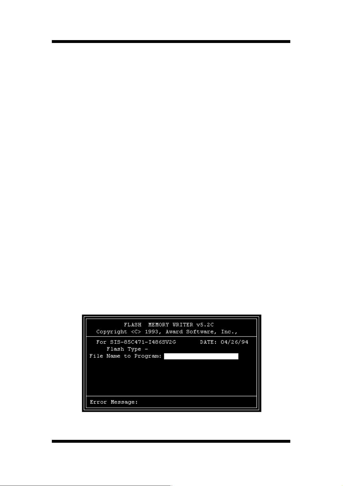
4. The AWDFLASH Utility Screen appears. You will be asked for the file name to program.
Type in the name of the new BIOS (.bin) file and hit [ENTER].
User’s Manual
51
Page 52

FLASH BIOS PROGRAMMING UTILITY
5. The program will then ask if you want to backup the old BIOS. This is recommended in case
there are any problems with the new .bin file. Enter the name of the new backup file (such as
backup.bin ) and press [ENTER].
6. At this time the system will prompt you for final confirmation before beginning programming.
The Utility can be aborted at this time by hitting n . To begin programming, hit y
7. When the Flash programming starts, a bar indicator will show the progress of the
programming operation. After successful completion, hit the reset button or power off the
computer.
Be sure to perform Load Optimized Defaults for your new BIOS to
synchronize the previous BIOS with the updated BIOS.
52
User’s Manual
Page 53
DMI UTILITY
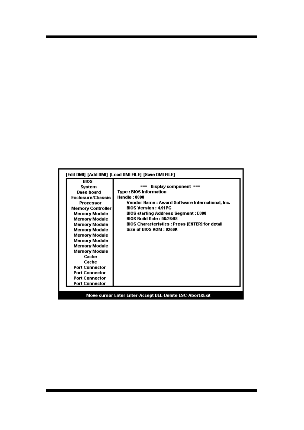
5. DMI UTILITY
This main board supports the Desktop Management Interface (DMI), which is a new method
of providing enterprise management for personal computers. The main component of DMI is
the Management Information Format Database (MIF), which contains information about the
computer system and its components, such as BIOS version/vendor, CPU speed/type,
memory size/type, L1/L2 cache, port connectors (IDE, floppy, 2S/1P, USB, keyboard, mouse),
slots etc. Using DMI,
remote PC management software is able to obtain various information about the system,
including hardware profiles, capabilities, operational status, installation dates, and other
information about the system and its components. This DMI utility, DMICFG.EXE found under
the Utilities folder of the supplied CD-ROM, allows you to add additional information, such as
serial numbers, vendor information, and enclosure/chassis configurations, into the MIF.
Note: The DMI utility must be run in real mode without the EMM386 memory manager
loaded.
52
User’s Manual
Page 54

INSTANTLY AVAILABLE PC
6. INSTANTLY AVAILABLE PC (Option)
(for the Main board Chipset with FW82815EP only)
6.1 What is an Instantly Available PC?
Instantly Available Technology Boosts PC Energy Savings and Improves PC's Ease of
Use at full system capability
Wouldn't it be nice if your personal computer is ready when you are, just like any home
appliance, with just a touch of a button? How about keeping your personal computer available
24 hours a day to answer phones, receive faxes, and connect users to each other, with power
consumption no more than a night light?
It's here the Instantly Available PC is here to bring these new capabilities to PC users!
With an Instantly Available PC, users can allow their PCs to power down to a very deep sleep
state, consuming very little power, while retaining the capability to respond to various external
or user programmed events such as a phone call, network alerts or a backup procedure. And
the wakeup is quick, within a few
seconds. So no more time-consuming shutdown/restart/reboot process to interrupt and
resume operation!
6.2 Core Technology Suspend to RAM (S3)
The ideal sleep state with the lowest power consumption for an Instantly Available PC is
Suspend to RAM (STR). In this state over 95% of the PC's power is shut off while the system
context is maintained in system memory, enabling a breakthrough in power savings while
maintaining full system capability and connectivity.
Suspend To RAM (STR) is defined by the Advanced Configuration and Power Interface
(ACPI) specification as the S3 sleep state. ACPI is a power management specification
proposed by Intel, Toshiba and Microsoft, which makes hardware status information available
to the operating system and is an Operating System Directed Power Management.
User’s Manual
53
Page 55

INSTANTLY AVAILABLE PC
☆ APM vs. ACPI
The old generation APM (Advanced Power Management) is a BIOS directed power
management can be activated to save energy, but at the expense of system performance
and/or connectivity due to its unawareness of the system states.
With ACPI and Suspend to RAM technology, the user will not have to make any tradeoffs
when it comes to power management. Network and modem connections will still be there and
you will enjoy full system capabilities along with aggressive power management.
6.3 The Key Ingredients
> An ACPI -enabled Operating System such as Microsoft Windows 98 or Windows 2000
family is required to direct the system-wide power management.
> BIOS on Motherboard must support ACPI and Suspend to RAM (STR) sleep state.
> Hardware circuits, especially Auxiliary Power Source and Split Power Planes must
be implemented on motherboard.
> Add-on adapters must support ACPI capabilities to make whole system Instantly
Available. Refer to Add-on Device Compatibility List.
> ATX power must comply with ATX 2.01 specification (Provide more than 720MA
Stand-By current at 5V)
54
User’s Manual
Page 56

INSTANTLY AVAILABLE PC
6.4 Installation
☆ Mainboard BIOS
Enable the ACPI option provided in the BIOS by:
1. Enter Power Management Setup of the BIOS.
2. Set ACPI function to Enabled.
3. Set ACPI Suspend Type to S3 (STR).
☆ Operating System
If your existing 98 system is in APM mode, update the system to ACPI mode as
follows:
1. Boot-up with Windows 98.
2. Open the "Control Panel" and double-click the "System" icon.
3. Click the "Device Manager" Tab and then the "System devices".
4. Double-click the "Plug and Play BIOS".
5. Click the "Driver" Tab and choose "Update Driver".
6. "Update Device Driver Wizard" starts. Click on the "Next" button.
7. The Wizard provides a choice between having the Wizard search for a
better driver than the one in use or displaying a list of drivers from a
specific location. Choose "Display" and click on the "Next" button.
8. Select "Show all hardware" and then "Advanced Configuration and
Power Interface (ACPI) BIOS".
9. Click on the "Next" button.
10. An "Update Driver Warning" dialog box appears. Click on the "Yes"
button.
11. "Update Device Driver Wizard" will starts again. Click on the "Next"
button.
12. When copying files to the system is completed, click on the "Finish"
button.
13. Restart the computer. Your windows 98 system is in the ACPI mode.
User’s Manual
55
Page 57

INSTANTLY AVAILABLE PC
6.5 Using Suspend to RAM
☆ How to put your system into Suspend to RAM (STR) sleep state
There are several ways to initiate Suspend to RAM(STR):
Note: The Message LED should be blinking while system is in standby, Suspend to RAM
mode. Depending on the mainboard and the chassis designs, the Message LED may be
the Power LED or other LED on the front panel of the chassis.
☆ Using the mouse button:
1. From the "Start" menu in Windows 98, select "Shut Down".
2. Select "Stand by" in the Shut Down Windows dialog box.
3. Press "OK" to enter the "Suspend to RAM (STR)" sleep state.
☆ Setting the standby time
1. Enter "Control Panel".
2. Double-click the "Power Management" icon.
3. "Power Management Properties" dialog box appears. Select "Power Schemes" tab.
4. Use "System standby" option to set the time for the system to
automatically enter standby mode when the system is not in use.
☆ Using the system power button:
1. Enter "Control Panel".
2. Double-click the "Power Management" icon.
3. In the Power Management Properties dialog box, select "Advanced" tab.
4. Define the System Power Button to be "Standby" or "Shutdown":
☆ Standby
When the power switch of the front bezel or "Sleep" key of the Windows
98 keyboard is pressed, Windows 98 will enter "Suspend to RAM"
mode and later can be waken up by pressing the "Wakeup" key or power
switch.
Now you can press the Power on button to enter the "Suspend to RAM
(STR)" sleep state.
☆ Shutdown
System is turned off almost immediately without corrupting the data.
56
User’s Manual
Page 58

INSTANTLY AVAILABLE PC
☆ Using the Windows 98 keyboard buttons:
Press the "Sleep" button to enter the Suspend to RAM mode.
Note: 1. The "Power Off" button on the Windows 98 keyboard can also be used
toenter the standby mode as described above.
2. You need to set the mainboard BIOS to use the "Wakeup" button.
Please see the following section.
☆ How to recover your system from "Suspend to RAM (STR)" sleep state
You can set the way to wake up the system from the mainboard BIOS Setup:
☆ At the Integrated Peripherals Setup Screen, under "Wake Up Events":
☆ Keyboard Resume Enabling this option allows pressing any key on the
keyboard to wake up a system which has been powered down.
☆ Wake Up On LAN/Ring An input signal on the serial Ring Indicator (RI)
line in other words, an incoming call on the modem (either external
modem or internal modem card) power on the system.
With a LAN card installed, the Wake-up On LAN function allows the network to
wake up a Soft Power Down (Soft-Off) PC.
☆ RTC Alarm Resume - When enabled, the system will automatically power on or
returns to full power out of suspend/standby mode at the time and date of the
month (0 for daily) specified.
6.6 Related Documents
■ ACPI, Advanced Configuration and Power Interface Revision 1.0b,
http://www.teleport.com/~acpi/spec.htm
■ ACPI Implementers' Guide,
http://www.teleport.com/~acpi/impguid.htm
■ Instantly Available PC Technology,
http://developer.intel.com/technology/iapc/
■ On Now White papers,
http://www.microsoft.com/hwdev/onnow.htm/
User’s Manual
57
Page 59
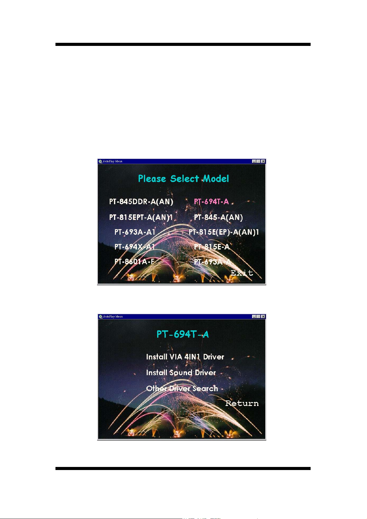
S o f t w a r e I n s t a l l a t I o n
7. Software Installation
7.1 Please Select Model Name
Included in the Motherboard package you can find a CD-disk which
contains the support drivers & utilities. Please insert this support
CD-disk into your CD-ROM drive of PC, wait for the Autorun Screen
then click "PT-694T-A" for into the drivers & utilities installation.
Step1
Step2
User’s Manual
57
Page 60
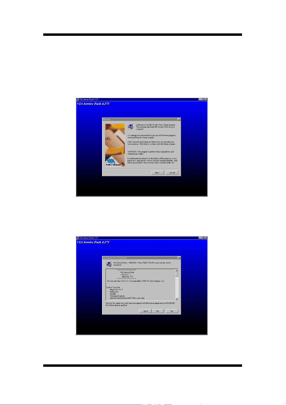
S o f t w a r e I n s t a l l a t I o n
7.2 Install VIA 4in1 Drivers
Clik "Install VIA 4in1 Drivers".
Please follow the step charts below for installation.
Step1
Step2
58
User’s Manual
Page 61
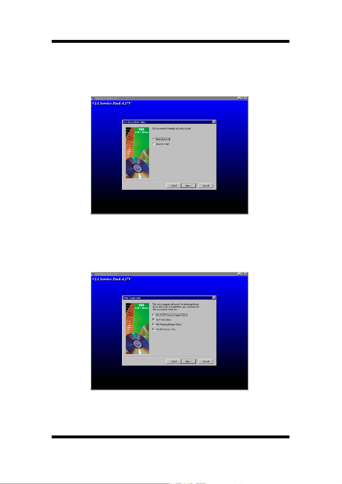
S o f t w a r e I n s t a l l a t I o n
Step3
Step4
User’s Manual
59
Page 62
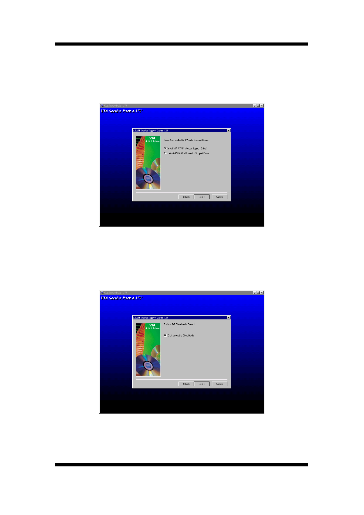
S o f t w a r e I n s t a l l a t I o n
Step5
Step6
60
User’s Manual
Page 63
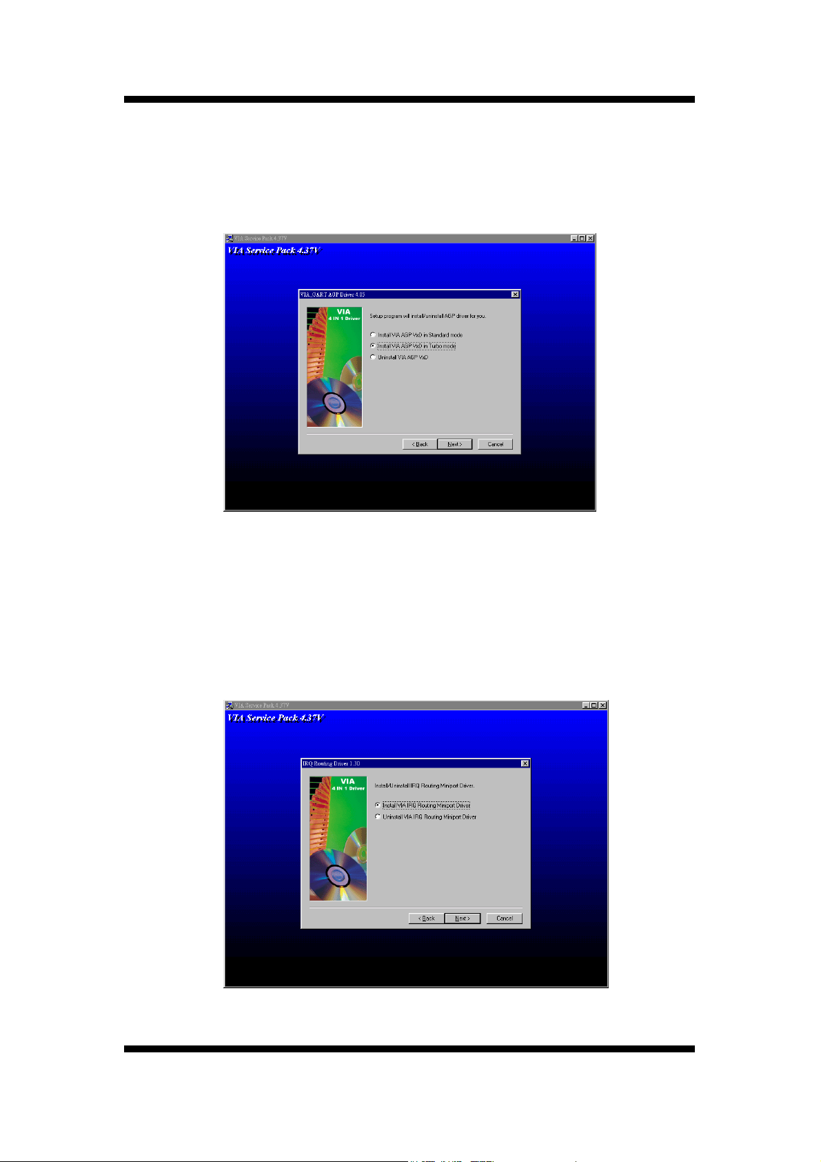
S o f t w a r e I n s t a l l a t I o n
Step7
Step8
User’s Manual
61
Page 64
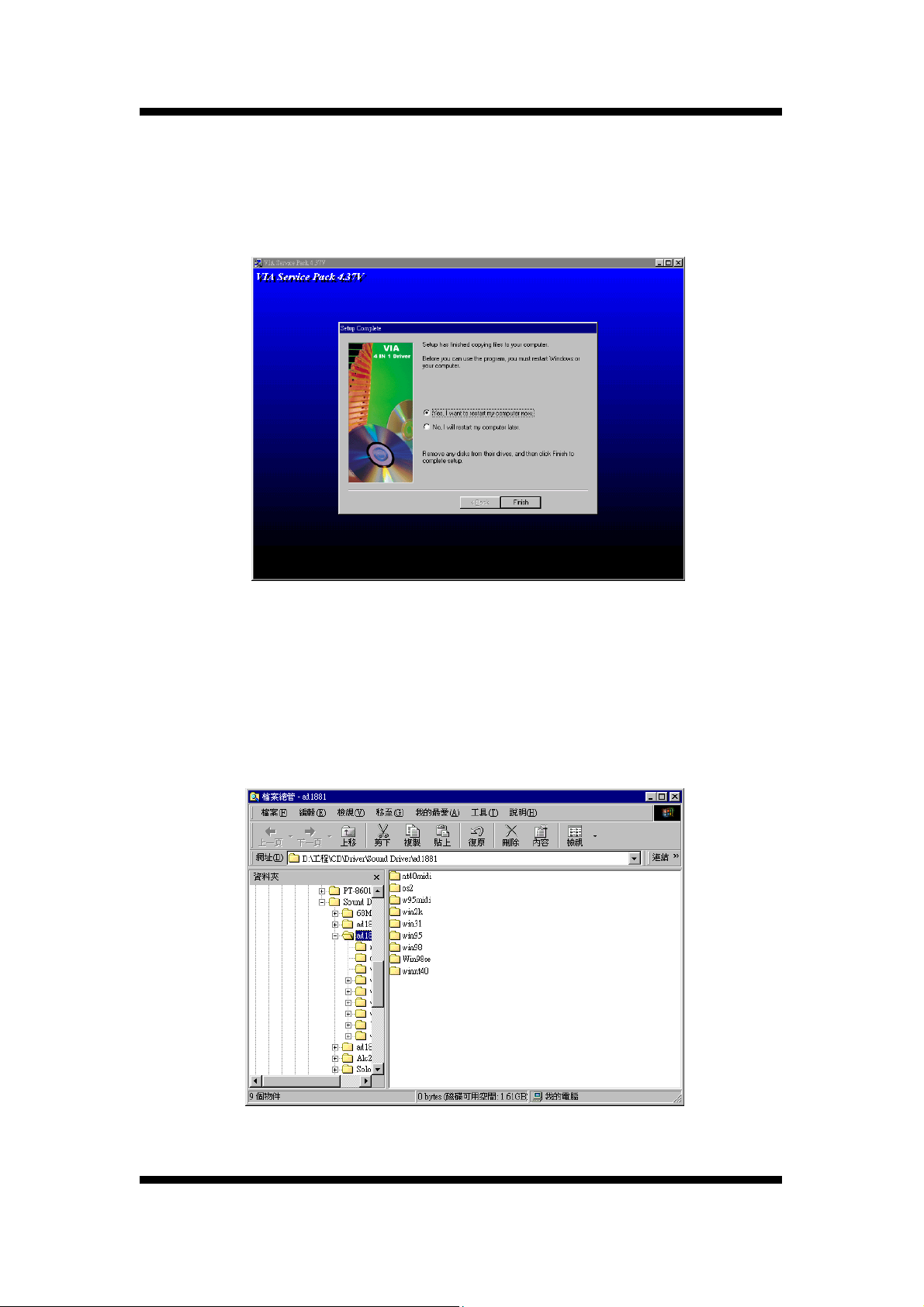
S o f t w a r e I n s t a l l a t I o n
Step9
7.3 Install Sound Driver
Click "Install Sound Driver"
Please follow the step charts below for intallation
Step1
62
User’s Manual
Page 65
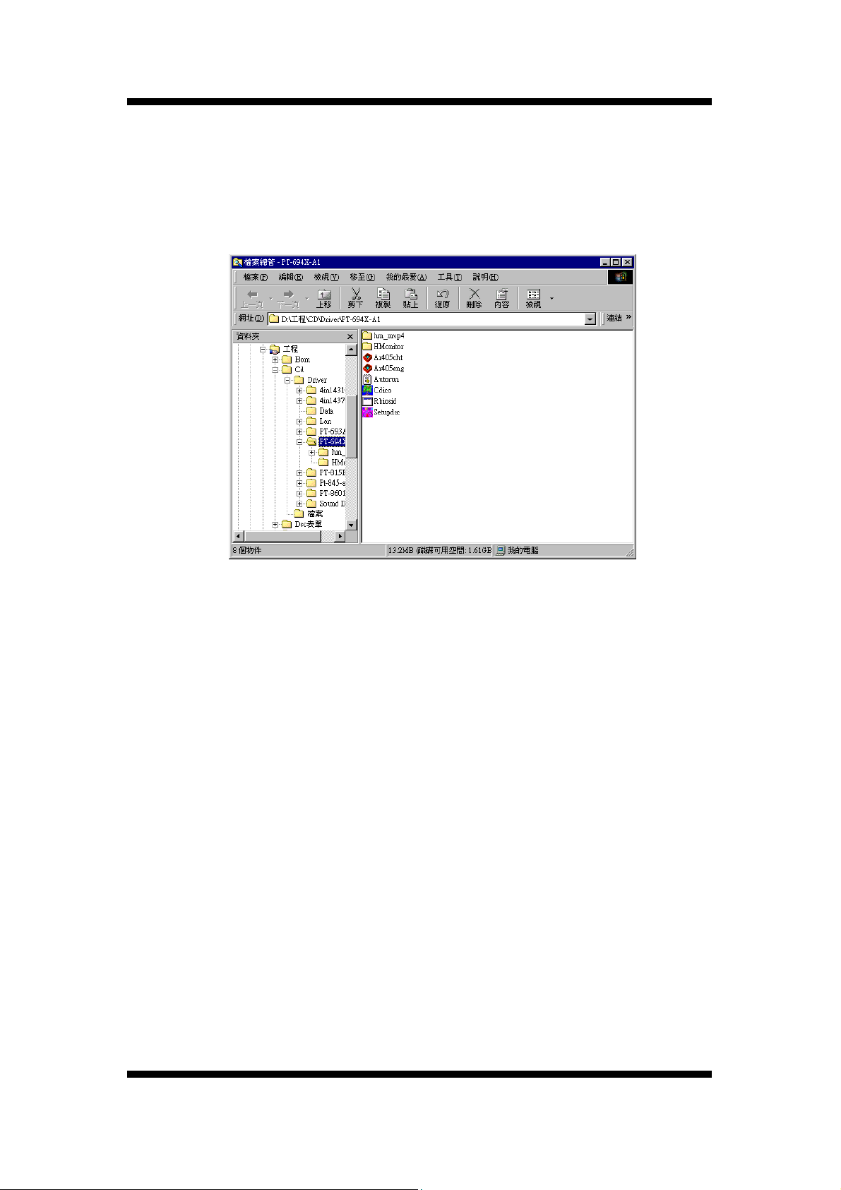
S o f t w a r e I n s t a l l a t I o n
7.3 Other Driver Search
Click "Other Driver Search" for other drivers & utilities demand.
Step1
User’s Manual
63
Page 66
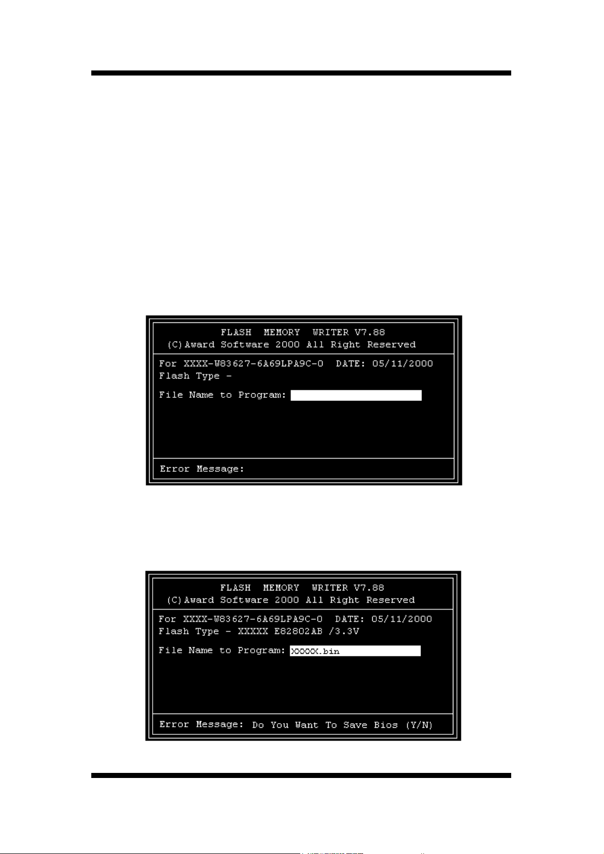
Appendix
8. Appendix
8.1 Update Your system BIOS
Download the XXXXX.EXE file corresponding to your model form the our website to
an empty directory on your hard disk or floppy. Run the downloaded XXXXX.EXE
file and it will self extract. Copy these extracted files to a bootable DOS floppy disk.
Note: The DOS floppy disk should contain NO device drivers or other programs.
1. Type “A:\AWDFLASH and press <Enter> Key.
2. You will see the following setup on screen.
3. Please key in the XXXXX.bin BIOS file name.
4. If you want to save the previous BIOS data to the diskette, please key in [Y],
otherwise please key in [N].
64
User’s Manual
Page 67
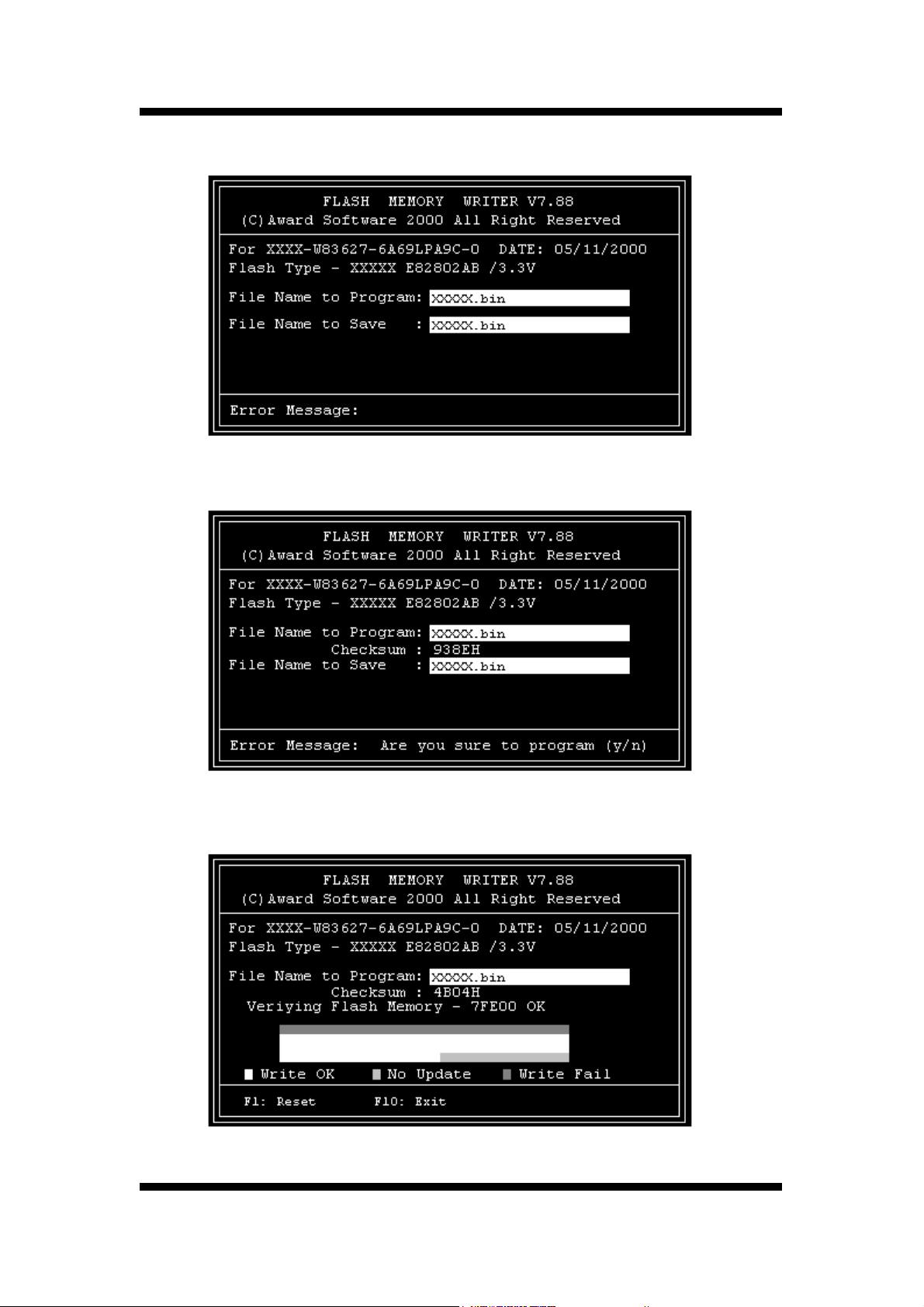
Appendix
5. Key in File Name to save previous BIOS to file.
6. Are you sure to program (y/n), please key in [Y] to start the programming.
7. The programming is finished.
User’s Manual
65
 Loading...