

Page 1

MANUFACTURING
A
S
D
L
I
S
T
E
CM
O
I
N
N
I
T
A
T
C
T
I
S
L
US
E
D
NUMBERS:
9400 1 3 0
9400 1 3 2
9400 1 3 4
9400 1 3 6
9400 1 4 0
9400 1 4 2
9400 1 4 4
9400 1 4 6
9400 1 5 0
9400 1 5 2
9400 1 5 4
9400 1 5 6
WARMER DRAWER
(Without Water Tray)
P/N 1010889 Rev. A 04/05
Models WD-20, WD21A, & WD-35A
WD-20 Shown
Owner’s Manual
Page 2
WARMER DRAWER
TABLE OF CONTENTS
Owner Information .....................................................
General ......................................................................2
Warranty Information .................................................2
Service/Technical Assistance ....................................3
Important Safety Information ....................................3
Specifications .............................................................5
Electrical Ratings .......................................................5
Capacity .....................................................................5
Shipping Weight ........................................................5
Electrical Cord & Plug Configurations .......................5
Dimensions ................................................................5
Installation ...................................................................6
Unpacking ..................................................................6
OWNER INFORMATION
2
Equipment Setup .......................................................
Operation .....................................................................7
Operating Instructions ...............................................7
Hi-Limit Reset ............................................................7
Maintenance ................................................................ 8
Cleaning ....................................................................8
Replacing Components .............................................8
Troubleshooting .........................................................9
Wiring Diagram .........................................................10
Replacement Parts – WD-20 .................................... 11
Replacement Parts – WD-21A & 35A ......................13
Notes..........................................................................15
Limited Warranty ......................................Back Cover
6
General
The Roundup Warmer Drawer warms up bread products. Easily adjustable controls allow you to tailor the
temperature required for your bread product.
The Warmer Drawers are designed to be used sepa
rately, stacked or to fit under the Roundup Hot Dog
Corrals.
This manual provides the safety, installation and oper
ating procedures for the Warmer Drawer. We recom
mend that all information contained in this manual be
read prior to installing and operating the unit.
Your Warmer Drawer is manufactured from the finest
materials available and is assembled to Roundup’s
strict quality standards. This unit has been tested at
the factory to ensure dependable trouble-free opera
tion.
-
-
Warranty Information
Please read the full text of the Limited Warranty in this
manual.
If the unit arrives damaged, contact the carrier imme
-
-
diately and file a damage claim with them. Save all
packing materials when filing a claim. Freight damage
claims are the responsibility of the purchaser and
not covered under warranty.
The warranty does not extend to:
• Damages caused in shipment or damage as
result of improper use.
• Installation of electrical service.
• Normal maintenance as outlined in this manual.
• Malfunction resulting from improper maintenance.
• Damage caused by abuse or careless handling.
• Damage from moisture into electrical
components
• Damage from tampering with, removal of, or
changing any preset control or safety device.
-
are
IMPORTANT! Keep these instructions for future reference.
If the unit changes ownership, be sure this manual accompanies the equipment.
2
P/N 1010889 Rev. A 04/05
Page 3
OWNER INFORMATION (continued)
WARMER DRAWER
Service/Technical Assistance
If you experience any problems with the installation
or operation of your unit, contact your local Roundup
Authorized Service Agency.
Fill in the information below and have it handy when
calling your authorized service agency for assistance.
The serial number is on the specification plate located
on the unit.
Purchased From:
Date of Purchase:
Model No.:
Serial No.:
Mfg. No.:
Refer to the service agency directory included with your
unit.
IMPORTANT SAFETY INFORMATION
Authorized Service Agency
Name:
Phone No.:
Address:
Use only genuine Roundup replacement parts in this
unit. Use of replacement parts other than those sup
plied by the manufacturer will void the warranty. Your
Authorized Service Agency has been factory trained
and has a complete supply of parts for this unit.
You may also contact the factory at
you have trouble locating your local authorized service
agency.
1-877-392-7854 if
-
Throughout this manual, you will find the following safety words and symbols that signify important safety issues with
regards to operating or maintaining the equipment.
WARNING
GENERAL WARNING. Indicates information important to the proper operation of the
equipment. Failure to observe may result
in damage to the equipment and/or severe
bodily injury or death.
CAUTION
GENERAL CAUTION. Indicates information important to the proper operation of the
equipment. Failure to observe may result in
damage to the equipment.
ELECTRICAL WARNING. Indicates information relating to possible shock hazard.
Failure to observe may result in damage to
the equipment and/or severe bodily injury or
death.
HOT SURFACE WARNING. Indicates information important to the handling of equip
ment and parts. Failure to observe caution
could result in personal injury.
WARNING
WARNING
-
P/N 1010889 Rev. A 04/05
3
Page 4
WARMER DRAWER
IMPORTANT SAFETY INFORMATION (continued)
In addition to the warnings and cautions in this manual,
use the following guidelines for safe operation of the
unit.
• Read all instructions before using equipment.
• For your safety, the equipment is furnished with
a properly grounded cord connector. Do not
attempt to defeat the grounded connector.
• Install or locate the equipment only for its intend
ed use as described in this manual. Do not use
corrosive chemicals in this equipment.
• Do not operate this equipment if it has a dam
aged cord or plug, if it is not working properly, or
if it has been damaged or dropped.
• This equipment should be serviced by qualified
personnel only. Contact the nearest Roundup
authorized service facility for repair.
• Do not block or cover any openings on the unit.
• Do not immerse cord or plug in water.
• Keep cord away from heated surfaces.
• Do not allow cord to hang over edge of table or
counter.
The following warnings and cautions appear
throughout this manual and should be carefully
observed.
• Turn the unit off, disconnect the power source
and allow unit to cool down before performing
any service or maintenance on the unit.
-
-
• The procedures in this chapter may include
the use of chemical products. These chemi
cal products will be highlighted with bold
face letters followed by the abbreviated HCS
(Hazard Communication Standard). See
Hazard Communication Standard manual for
the appropriated Material Safety Data Sheets
(MSDS).
• The unit should be grounded according to
local electrical codes to prevent the possibil
ity of electrical shock. It requires a grounded
receptacle with separate electrical lines, pro
tected by fuses or circuit breaker of the prop
er rating.
• All electrical connections must be in accor
dance with local electrical codes and any
other applicable codes.
• WARNING ELECTRICAL SHOCK HAZARD.
FAILURE TO FOLLOW THESE INSTRUCTIONS
COULD RESULT IN SERIOUS INJURY OR
DEATH.
- Electrical ground is required on this appli
ance.
- Do not modify the power supply cord plug.
If it does not fit the outlet, have a proper
outlet installed by a qualified electrician.
- Do not use an extension cord with this
appliance.
- Check with a qualified electrician if you
are in doubt as to whether the appliance is
properly grounded.
-
-
-
-
-
-
WARNING
ELECTRICAL SHOCK HAZARD. FAILURE TO
FOLLOW THE INSTRUCTIONS IN THIS MANUAL
COULD RESULT IN SERIOUS INJURY OR DEATH.
• Electrical ground is required on this appliance.
• Do not modify the power supply cord plug. If
it does not fit the outlet, have a proper outlet
installed by a qualified electrician.
• Do not use an extension cord with this appli
ance.
• Check with a qualified electrician if you are in
doubt as to whether the appliance is properly
grounded.
4
P/N 1010889 Rev. A 04/05
-
Page 5
POWER
HEATER
THERMOSTAT
OFF
1
2
3
4
5
6
7
8
9
10
SPECIFICATIONS
WHT
BLK
GRN
WARMER DRAWER
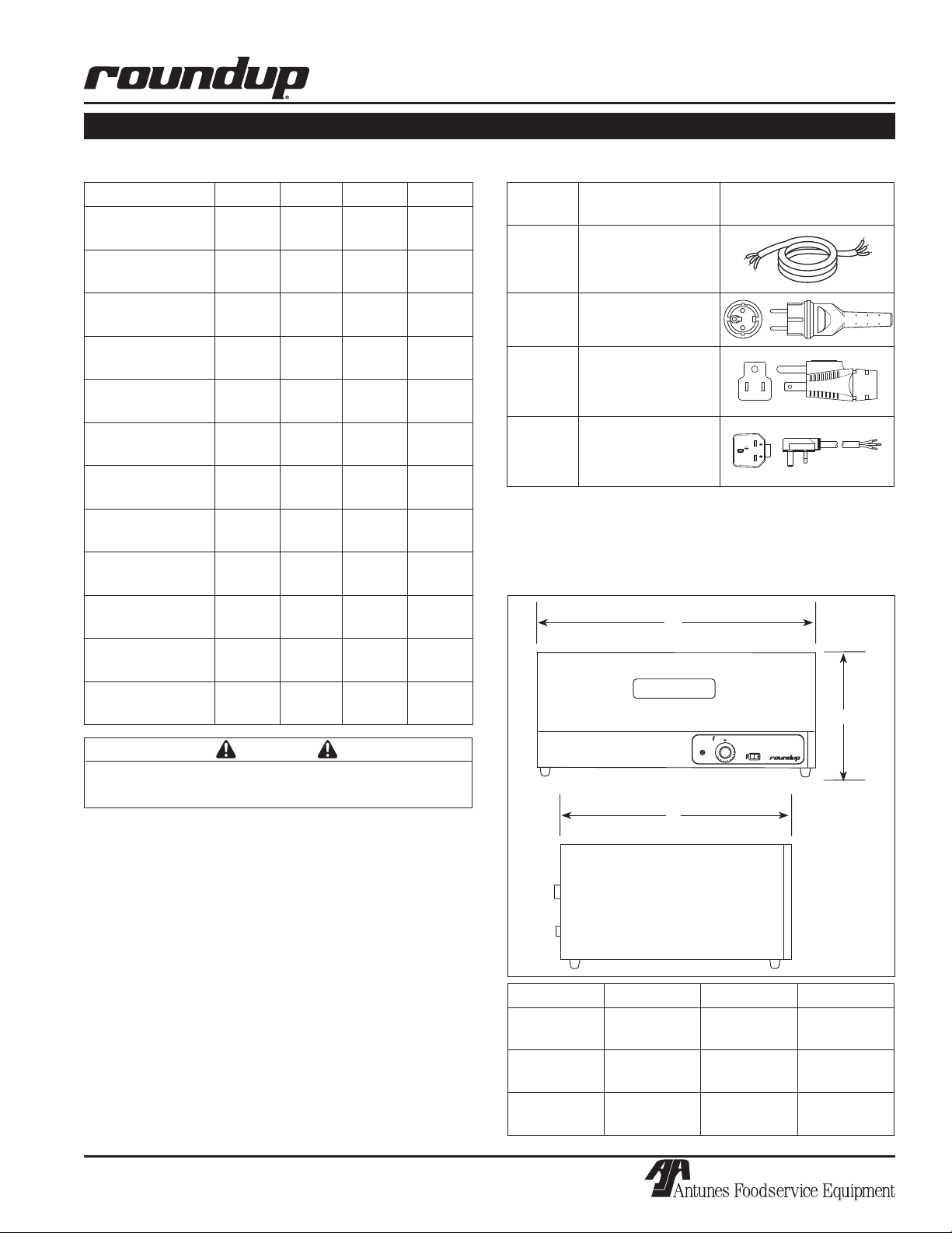
Electrical Ratings
Model & Mfg. No Volts Watts Amps Hertz
WD-20-CF
9400130
WD-20-HC
9400132
WD-20-CF
9400134
WD-20-HG
9400136
WD-21A-CF
9400140
WD-21A-HG
9400142
WD-21A-HC
9400144
WD-21A-CF
9400146
WD-35A-CF
9400150
WD-35A-HG
9400152
WD-35A-HC
9400154
WD-35A-CF
9400156
120 500 4.2 50/60
230 500 2.2 50/60
230 500 2.2 50/60
230 500 2.2 50/60
120 1000 8.3 50/60
230 1100 4.8 50/60
230 1100 4.8 50/60
230 1100 4.8 50/60
120 1400 11.7 50/60
230 1530 6.7 50/60
230 1530 6.7 50/60
230 1530 6.7 50/60
Electrical Cord & Plug Configurations
Letter
Code*
H
(H)C** CEE 7/7 16 Amp, 250
(C)F*** 5-15P, 15 Amp, 250
(H)G** BS-1365 Fused,
* Used in model designation
* * Indicates that the plug comes with a Harmonized Cord
** * Indicates that the plug comes with a Commercial Cord
Description Configuration
Harmonized Cord
VAC (Assembly Only)
VAC, Non-Locking
(Assembly Only)
Permaplug, 16 Amp,
250 VAC (Assembly
Only)
Dimensions
A
C
CAUTION
All electrical connections must be in accordance with
local electrical codes and any other applicable codes.
B
Capacity
WD-20 Holds up to 40 standard hot dog buns.
WD-21A One 4” (100 mm) deep full size steam table
pan. Holds 40-50 standard hot dog buns.
WD-35A Two 4” (100 mm) deep 2/3 size steam table
pan. Holds 50-60 standard hot dog buns.
Shipping Weight
WD-20 58 lbs. (27 kilos)
WD-21A 56 lbs. (26 kilos)
WD-35A 72 lbs. (33 kilos)
P/N 1010889 Rev. A 04/05
5
Model Width (A) Depth (B) Height (C)
WD-20 18-3/4”
(476 mm)
WD-21A 22-3/16”
(564 mm)
WD-35A 32-1/2”
(826 mm)
21”
(533 mm)
17”
(432 mm)
17”
(432 mm)
10-5/8”
(270 mm)
10-3/8”
(264 mm)
10-3/8”
(264 mm)
Page 6

WARMER DRAWER
INSTALLATION
Unpacking
1. Remove unit and all packing materials from shipping carton.
2. Open the large box. Remove all packing materi
als and protective coverings from the unit and
parts.
3. Wash removable parts in soap and water. Wipe
all surfaces of the unit with a hot damp cloth.
NOTE: Do not use a dripping wet cloth. Wring out
before use.
4. Install parts into unit.
NOTE: If any parts are missing or damaged, con
tact A.J. Antunes & Co. IMMEDIATELY at 1-877-392-
7854.
-
Equipment Setup
When placing the unit into service, pay attention to the
following guidelines.
• Make sure power to the unit is off and the unit is
at room temperature.
Inner Liner
-
Drawer
Figure 1. Warmer Drawer–WD-20
Trivet
Food Pan
• Do not block or cover any openings on the unit.
• Do not immerse cord or plug in water.
• Keep cord away from heated surfaces.
• Do not allow cord to hang over edge of table or
counter.
Connect the unit to the power supply. Refer to the
specification plate for the proper voltage.
CAUTION
All electrical connections must be in accordance with
local electrical codes and any other applicable codes.
WARNING
ELECTRICAL SHOCK HAZARD. FAILURE TO
FOLLOW THE INSTRUCTIONS IN THIS MANUAL
COULD RESULT IN SERIOUS INJURY OR DEATH.
• Electrical ground is required on this appliance.
• Do not modify the power supply cord plug. If
it does not fit the outlet, have a proper outlet
installed by a qualified electrician.
Drawer
Figure 2. Warmer Drawer–WD-21A & WD-35A
• Do not use an extension cord with this appliance.
• The unit should be grounded according to local
electrical codes to prevent the possibility of
electrical shock. It requires a grounded recep
tacle with separate electrical lines, protected by
fuses or circuit breaker of the proper rating.
• Check with a qualified electrician if you are in
doubt as to whether the appliance is properly
grounded.
-
6
P/N 1010889 Rev. A 04/05
Page 7

POWER
HEATER
THERMOSTAT
OFF
1
2
3
4
5
6
7
8
9
1
0
OPERATION
Operating Instructions
The recommended starting temperature for hot dog
buns and hard rolls is 140°F (60°C). Your opera
tion may require temperature adjustment up or down,
depending on product and usage.
-
WARMER DRAWER
Most products warm to serving temperature of
130°- 140°F (54°- 60°C) in 15-20 minutes and remain
ready to serve for up to 1½ hours, if the product
remains in its original packaging. If the product is
removed from its original packaging, the serving time is
reduced to 30-45 minutes.
1. Turn the Rocker Switch (power On/Off) to ON.
2. Set the thermostat control to the desired setting.
The heater ON light will be lit.
3. Load product into the drawer.
Hi-Limit Reset
A Hi-Limit Thermostat with a reset switch is contained
in the heating circuit. If the unit should overheat for
any reason, the Hi-Limit Thermostat opens and cuts off
power to the Heating Element.
To reset the Hi-Limit Thermostat:
1. Turn the Rocker Switch (power On/Off) to OFF,
unplug the power cord, and allow the unit to cool
down before proceeding.
Heater ON Light
Thermostat
Control
Figure 2. Controls
Rocker Switch
(Power On/Off)
2. Remove the Base Plate and push in the Reset
Switch located on the bottom of the Hi-Limit
Thermostat (Figure 3).
If the Hi-Limit Thermostat continually trips, contact your
Authorized Service Agency to determine the reason for
overheating.
P/N 1010889 Rev. A 04/05
Hi-Limit Reset
Switch
Figure 3. Hi-Limit Reset
7
Page 8

WARMER DRAWER
MAINTENANCE
WARNING
Turn the unit off, disconnect the power source and
allow the unit to cool down before performing any service or maintenance on the unit.
Cleaning
DAILY
1. Turn the unit off, unplug the power cord, and
allow the unit to cool down before proceeding.
2. Remove all parts from inside the Warmer Drawer.
Wash all parts in soap and water, rinse in clear
water, and wipe dry.
3. Wipe the exterior of unit with a damp cloth or
stainless steel cleaner, then wipe dry with a
clean, dry cloth.
4. Re-install all parts into Warmer Drawer.
NOTE: Failure to porperly clean and dry the parts
prior to re-assembly may result in the accumula
tion of water/moisture overnight. This may lead to
permanent damage of the equipment finish and its
accessories. This damage is permanent and not
covered by warranty.
-
3. Wipe the exterior of unit with a damp cloth or
stainless steel cleaner, then wipe dry with a clean,
dry cloth.
4. Re-install all parts into unit.
Replacing Components
NOTE: It is recommended that all service procedures be performed by a qualified authorized ser
vice technician.
Press down simultane-
ously on both the left and
right interlocking tabs to
release the Drawer
Drawer
Side
Rail
Drawer
Figure 4. Removing Drawer
-
CAUTION
To prevent damage to the unit, do not use abrasive
cleaners on the unit.
WARNING
Use caution when using caustic cleaning solutions.
Read all manufacturer label instructions to avoid personal injury.
WEEKLY
1. Turn the unit off, unplug the power cord, and allow
the unit to cool down before proceeding.
2. Remove all parts from the Warmer Drawer. Wash
all parts in soap and water, rinse in clear water,
and wipe dry.
3. Pull the Drawer out (Figure 4). Push down simul
taneously on both the interlocking tabs (above
each drawer side rail - Figure 4) and pull the
Drawer away from unit.
4. Wipe the interior of the Warmer Drawer with a
clean, damp cloth. Then, whipe dry with a clean,
dry cloth.
8
P/N 1010889 Rev. A 04/05
Page 9

WARMER DRAWER
TROUBLESHOOTING
WARNING
To avoid possible personal injury and/or damage to the unit, inspection, test and repair of electrical
equipment should be performed by qualified service personnel. The unit should be unplugged when
servicing.
Problem Possible Cause) Corrective Action
Unit will not heat up. Power Cord is not Plugged in. Plug the Power Cord into the appropriate
outlet.
Circuit Breaker is tripped. Reset the Circuit Breaker. Contact your elec
trician if the breaker trips again.
Hi-Limit Thermostat is tripped or
inoperable.
Loose, broken, or burnt wiring in
Heating Circuit.
Faulty Heating Element. Contact your maintenance person or
Faulty Thermostat Control. Contact your maintenance person or
Product becomes hard and
dry.
Unit is getting too hot. Thermostat Control is set too high. Readjust the Thermostat Control.
Thermostat Control is too high. Readjust the Thermostat Control.
Product is not being kept in its origi
nal packaging.
Product is kept beyond the normal
holding times.
Faulty Thermostat Control. Contact your maintenance person or
Reset the Hi-Limit Thermostat according
to Figure 3. If the unit still does not heat
up, contact your maintenance person or
Authorized Service Agency for service.
Contact your maintenance person or
Authorized Service Agency for service.
Authorized Service Agency for service.
Authorized Service Agency for service.
-
Refer to the Operating Instructions section of
this Manual.
Refer to the Operating Instructions section of
this manual.
Authorized Service Agency for service.
-
P/N 1010889 Rev. A 04/05
9
Page 10

WARMER DRAWER
BLK
WHT
54
21
POWER
SWITCH
WHTWHT
BLKBLK
GND
GRN
TERMINAL
POWER
BLOCK
CORD
WHT
BLK
HI-LIMIT
THERMOSTAT
INDICATOR
LIGHT
HEATER
BLK/BRN
WHT/BLU
GRN
GRN-YEL
ELEMENT
UNLESS OTHERWISE SPECIFIED.
NOTE: ALL WIRES TO BE 16 GA. TFE-200°C
THERMOSTAT
WIRING DIAGRAM
10
P/N 1010889 Rev. A 04/05
Page 11

REPLACEMENT PARTS – WD-20
7
6
17 31
32
34
18
3
5
29
1
2
29
4
19
8
13
20
9
22
21
16
15
14
26
29
29
29
12
25
23
23
24
33
30
WARMER DRAWER
P/N 1010889 Rev. A 04/05
11
Page 12

WARMER DRAWER
REPLACEMENT PARTS – WD-20 (continued)
Item Part Description Qty.
No.
1 0010439 Housing, Outer 1
2 0021345 Liner Weldment, Inner 1
3 0502937 Base Plate 1
4 0504278 Control Panel 1
5 210K230 Bumper Leg Kit 1
6 0700463 Power Cord, 120 Volt 1
0700453 Power Cord, 230 Volt 1
7 040K251 Strain Relief Kit 1
8 4010151 Rocker Switch, Power On/Off
120 Volt 1
4010137 Rocker Switch, Power On/Off
230 Volt 1
9 403K115 Thermostat Kit, F° (Incl. #20) 1
403K160 Thermostat Kit, C° (Incl. #20) 1
12 4030225 Heating Element,
120 Volt, 500 Watt 1
4030231 Heating Element,
230 Volt, 500 Watt 1
13 4060323 Indicator Light, Heater ON,
120 Volt 1
4060229 Indicator Light, Heater ON,
230 Volt 1
14 0011825 Drawer Assembly
(Incl. # 15 & 16) 1
15 0501662 Drawer Front 1
Item Part Description Qty.
No.
16 210K128 Handle Kit 1
17 7000136 Terminal Block Kit 1
18 4030291 Thermostat, Hi-Limit 1
19 1000925 Label 1
20 2100110 Knob, F° 1
2100224 Knob, C° 1
21 300P108* Tube Clip, Thermostat Bulb 1
22 300P107* Tube Clip, Heating Element 1
23 210K195 Bearing Kit 2
24 7000649 Lock Lever Kit, LH 1
7000648 Lock Lever Kit, RH 1
25 0501654 Rear Panel 1
26 0504272 Liner, Drawer - Inner 1
27 0800239 Trivet (not shown) 1
28 0700504 Wire Set (not shown) 1
29 308P157* Screw, #8-32 x 3/8” 1
30 308P124* Screw, #8-32 x 1/2” 1
31 308P143* Nut, #8-32 1
32 306P123* Screw, #6-32 x 7/8” 1
33 306P130* Nut, #6-32 KEPS 1
34 308P133* Screw, #8-32 x 1/4” 1
* Only available in packages of 1
0.
12
P/N 1010889 Rev. A 04/05
Page 13

7
6
17
32
33
18
3
5
29
12
1
2
29
24
23
16
15
27
26
23
4
19
8
13
20
9
22
21
29
25
31
30
31
14
WARMER DRAWER
REPLACEMENT PARTS – WD-21A & 35A
P/N 1010889 Rev. A 04/05
13
Page 14

WARMER DRAWER
REPLACEMENT PARTS – WD-21A & 35A (continued)
Item Part Description Qty.
No.
1 0501894 Cover (WD-21A) 1
0501199 Cover (WD-35A) 1
2 0021347 Liner Weldment, Inner (WD-21A) 1
0021350 Liner Weldment, Inner (WD-35A) 1
3 0501841 Base Plate (WD-21A) 1
0501196 Base Plate (WD-35A) 1
4 0504285 Panel, Control (WD-20) 1
0504293 Panel, Control (WD-35) 1
5 210K230 Bumper Leg Kit 1
6 0700463 Power Cord, 120 Volt 1
0700453 Power Cord, 230 Volt 1
7 4010151 Strain Relief 1
8 4010151 Rocker Switch, Power On/Off,
120 Volt 1
4010137 Rocker Switch, Power On/Off,
230 Volt 1
9 403K102 Thermostat Kit, F° (Incl. #20) 1
403K160 Thermostat Kit, C° (Incl. #20) 1
12 4030172 Heating Element, 1000 watt
120 Volt (WD-21A) 1
4030173 Heating Element, 1100 watts
230 Volt (WD-21A) 1
4030175 Heating Element 1400 watts
120 Volt (WD-35A) 1
4030176 Heating Element 1530 watts
230 Volt (WD-35A) 1
13 4060323 Indicator Light, Heater ON,
120 Volt 1
4060229 Indicator Light, Heater ON,
230 Volt 1
Item Part Description Qty.
No.
14 0011831 Drawer Assembly (WD-21A)
(Incl. # 15 & 16) 1
0011839 Drawer Assembly (WD-35A)
(Incl. # 15 & 16) 1
15 0500783 Drawer Front (WD-21A) 1
0500820 Drawer Front (WD-35A) 1
16 2100106 Handle 1
17 7000136 Terminal Block 1
18 4030291 Thermostat, Hi-Limit 1
19 1000925 Label 1
20 2100110 Knob, F° 1
2100224 Knob, C° 1
21 300P108 Tube Clip, Thermostat Bulb 1
22 300P107 Tube Clip, Heating Element 1
23 210K195 Bearing Kit 4
24 7000649 Lock Lever Kit, LH 1
7000648 Lock Lever Kit, RH 1
25 0504286 Bracket, Heater Retainer 1
26 2130171 Pan, Perforated, Full Size 1
(WD-21A)
2130117 Pan (WD-35A) 2/3 size 2
27 0800383 Trivet, Full Pan (WD-21A) 1
0800109 Trivet (WD-35A) 2
28 0700504 Wire Set (not shown) 1
29 308P133* Screw, #8-32 x 1/4” 1
30 308P124* Screw, #8-32 x 1/2” 1
31 308P143* Nut, #8-32 1
32 306P123* Screw, #6-32 x 7/8” 1
33 306P104* Screw, #6-32 x 1/4” 1
* Only available in packages of 1
0.
14
P/N 1010889 Rev. A 04/05
Page 15

NOTES
WARMER DRAWER
P/N 1010889 Rev. A 04/05
15
Page 16

Limited Warranty
A.J. Antunes & Co.
Headquarters/Manufacturing
180 Kehoe Boulevard
Carol Stream, Illinois 60188 USA
Phone (630) 784-1000
Toll Free (800) 253-2991
Fax: (630) 784-1650
Antunes Equipment
Manufacturing (Suzhou) Ltd.,
9 Hou Ju Road, Building #24,
S&T Park, SND
Suzhou, Jiangsu, China 215011
Phone: 86-512-6841-3637
Fax: 86-512-6841-3907
www.ajantunes.com
Equipment manufactured by Roundup Food Equipment Division of A.J. Antunes & Co. has been constructed of the finest
materials available and manufactured to high quality standards. These units are warranted to be free from mechanical
and electrical defects for a period of one year from date of purchase or 18 months from shipment from factory, whichever
occurs first, under normal use and service, and when installed in accordance with manufacturer’s recommendations.
To insure continued proper operation of the units, follow the maintenance procedure outlined in the Owner’s Manual.
1. This warranty does not cover cost of installation, defects caused by improper storage or handling prior to placing of the
Equipment. This warranty does not include overtime charges or work done by unauthorized service agencies or personnel.
This warranty does not cover normal maintenance, calibration, or regular adjustments as specified in operating and mainte
nance instructions of this manual, and/or labor involved in moving adjacent objects to gain access to the Equipment. This
warranty does not cover consumable items such as platen release sheet and conveyor belt wraps. This warranty does not
pay travel, mileage, or any other charges for an authorized service agency to reach the equipment location.
2. Roundup reserves the right to make changes in design or add any improvements on any product. The right is always reserved
to modify equipment because of factors beyond our control and government regulations. Changes to update equipment do
not constitute a warranty charge.
3.
If shipment is damaged in transit, the purchaser should make a claim directly upon the carrier. Careful inspection should
be made of the shipment as soon as it arrives and visible damage should be noted upon the carrier’s receipt. Damage
should be reported to the carrier. This damage is not covered under this warranty.
4. Warranty charges do not include freight or foreign, excise, municipal or other sales or use taxes. All such freight and taxes
are the responsibility of the purchaser.
5. THIS WARRANTY IS EXCLUSIVE AND IS IN LIEU OF ALL OTHER WARRANTIES, EXPRESSED OR IMPLIED, INCLUDING
ANY IMPLIED WARRANTY OR MERCHANTABILITY OR FITNESS FOR A PARTICULAR PURPOSE, EACH OF WHICH IS
HEREBY EXPRESSLY DISCLAIMED. THE REMEDIES DESCRIBED ABOVE ARE EXCLUSIVE AND IN NO EVENT SHALL
ROUNDUP BE LIABLE FOR SPECIAL CONSEQUENTIAL OR INCIDENTAL DAMAGES FOR THE BREACH OR DELAY IN
PERFORMANCE OF THIS WARRANTY.
-
 Loading...