

Page 1
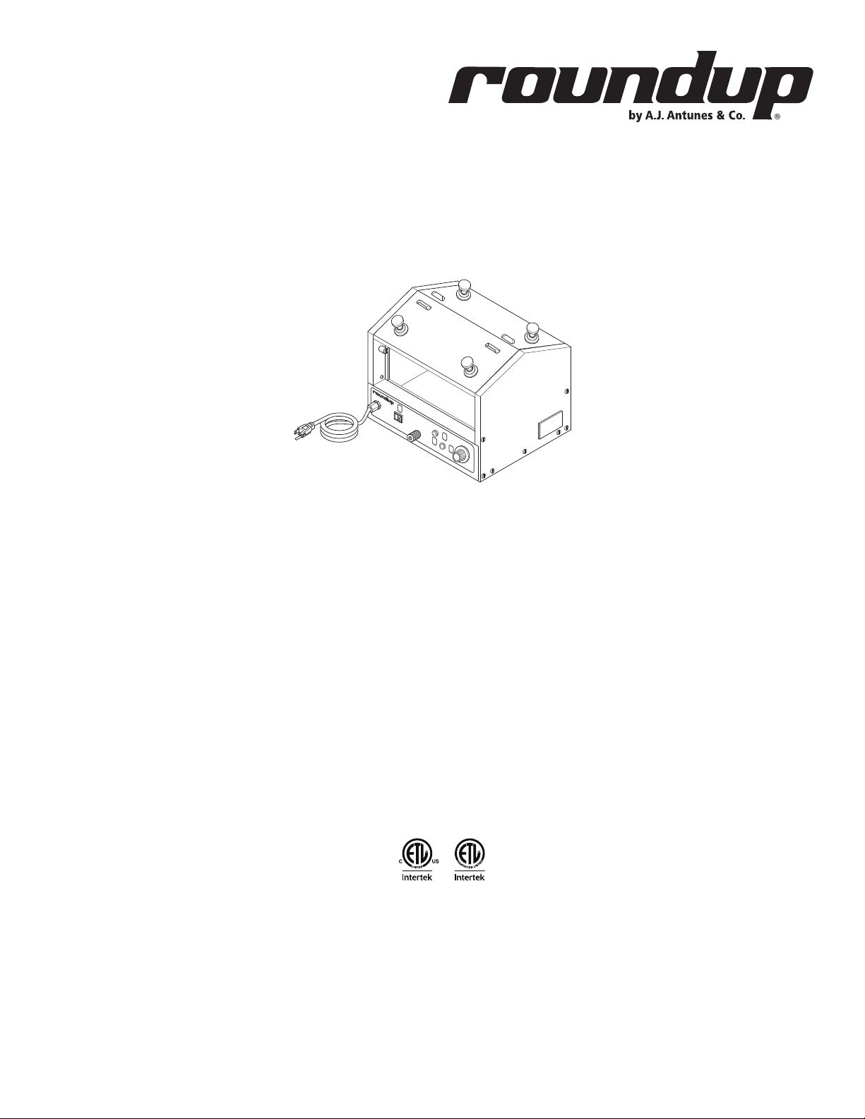
Hot Dog Hutch
Models HDH-3, HDH-3DR, & HDH-4
owner’s manual
Manufacturing Numbers:
9300100, 9300101, 9300102, 9300104, 9300106,
9300108, 9300112, 9300116, 9300118, 9300120,
9300124, 9300125, 9300130, 9300132
www.ajantunes.com
P/N 1010736 Rev. G 05/14
Page 2

CONTENTS
General 2
Warranty
Information 2
Service/Technical
Assistance 2
Important Safety
Information 3
Warnings 3
Specications 4
Electrical Ratings 5
Capacities 5
Installation 6
Unpacking 6
Equipment Setup 6
Operating
Instructions 7
Hi-Limit Reset Button 7
Maintenance 8
Daily Cleaning 8
Troubleshooting 9
Wiring Diagram 10
HDH-3 Racks & Baskets 13
HDH-3DR Racks 14
HDH-3DR
(Mfg. # 9300112 ONLY) 15
HDH-3DR
(Mfg. # 9300125 ONLY) 16
Limited Warranty 19
IMPORTANT
A.J. Antunes & Co. reserves the right to
change specications and product de-
sign without notice. Such revisions do not
entitle the buyer to corresponding changes,
improvements, additions or replacements
for previously purchased equipment.
GENERAL
This manual provides the safety, installation,
and operating procedures for your toaster.
Please read all of the information contained
in this manual prior to installing and operating the toaster.
This product is manufactured from the
finest materials available and is assembled
to Roundup’s strict quality standards. This
toaster was tested at the factory to ensure
dependable trouble-free operation.
WARRANTY
INFORMATION
Please read the full text of the Limited Warranty in this manual.
If the unit arrives damaged, contact the
carrier immediately and file a damage claim
with them. Save all packing materials when
filing a claim. Freight damage claims are the
responsibility of the purchaser and are not
covered under warranty.
The warranty does not extend to:
y Damages caused in shipment or
damage as result of improper use.
y Installation of electrical service.
y Normal maintenance as out-
lined in this manual.
y Malfunction resulting from
improper maintenance.
y Damage caused by abuse
or careless handling.
y Damage from moisture into
electrical components.
Damage from tampering with, removal of,
or changing any preset control or safety
device.
SERVICE/TECHNICAL
ASSISTANCE
If you experience any problems with the
installation or operation of your system,
contact A.J. Antunes & Co. at 1-630-7841000, or toll free in the United States at
1-800-392-7854.
Fill in the information in the next column
and have it handy when calling for assistance. The serial number is on the specification plate located on the system.
Purchased From
Date of Purchase
Model Number
Serial Number
Mfg. Number
Use only genuine Roundup replacement
parts in this unit. Use of replacement parts
other than those supplied by the manufacturer will void the warranty. Your Authorized
Service Agency has been factory trained
and has a complete supply of parts for this
unit.
Visit www. ajantunes.com or contact the
factory at 1-630-784-1000 to locate your
nearest Authorized Service Agency. Refer
to the service agency directory packaged
with your manual and fill in the information
below.
Authorized Service Agency
IMPORTANT
Keep these instructions for future refer-
ence. If the unit changes ownership, be sure
this manual accompanies the equipment.
Name
Phone Number
Address
2
P/N 1010736 Rev. G 05/14
Page 3

IMPORTANT SAFETY
INFORMATION
Use the following guidelines for safe operation of the unit.
y Read all instructions be-
fore using equipment.
y For your safety, the equipment is
furnished with a properly grounded
cord connector. Do not attempt to
defeat the grounded connector.
y Install or locate the equipment only
for its intended use as described in
this manual. Do not use corrosive
chemicals in this equipment.
y Do not operate this equipment if
it has a damaged cord or plug, if
it is not working properly, or if it
has been damaged or dropped.
y This equipment should be serviced
by qualified personnel only. Contact
your nearest Authorized Service
Agency for adjustment or repair.
y Do not block or cover any
openings on the unit.
y Do not immerse cord or plug in water.
y Keep cord away from heated surfaces.
y Do not allow cord to hang over
edge of table or counter.
y Turn the power off, unplug the
power cord, and allow unit to cool
down before performing any service
or maintenance on the unit.
y The equipment should be grounded
according to local electrical codes
to prevent the possibility of electri-
cal shock. It requires a grounded
receptacle with separate electrical
lines, protected by fuses or circuit
breaker of the proper rating.
y All electrical connections must be in
accordance with local electrical codes
and any other applicable codes.
y Do not clean this appli-
ance with a water jet.
WARNINGS
Be advised of the following warnings when
operating and performing maintenance on
this unit.
y If the supply cord is damaged, it must
be replaced by the manufacturer or
its service agent or a similarly qualified person in order to avoid a hazard.
y Do not modify the power sup-
ply cord plug. if it does not fit the
outlet, have a proper outlet installed by a qualified electrician.
y Do not use an extension
cord with this appliance.
y Electrical ground is re-
quired on this appliance.
y Check with a qualified electri-
cian if you are unsure if the appliance is properly grounded.
y If a chemical cleaner is used, be
sure it is safe to use on cast aluminum. Observe all precautions
and warnings on product label.
y Inspection, testing, and repair
of electrical equipment should
only be performed by qualified service personnel.
y This equipment is to be installed to
comply with the basic plumbing code
of the Building Officials and Code
Administrators, Inc. (BOCA) and the
Food Service Sanitation Manual of the
Food and Drug Administration (FDA).
y Do not use abrasive materials.
The use of these may cause damage to the stainless steel finish.
y Chlorides or phosphates in clean-
ing agents (e.g. bleach, sanitizers,
degreasers or detergents) could cause
permanent damage to stainless steel
equipment. The damage is usually in
the form of discoloration, dulling of
metal surface finish, pits, voids, holes,
or cracks. This damage is permanent
and not covered by warranty.
The following tips are recommended for
maintenance of your stainless steel equipment:
y Always use soft, damp cloth for
cleaning, rinse with clear water and
wipe dry. When required, always rub
in direction of metal polish lines.
y Routine cleaning should be
done daily with soap, ammonia detergent, and water.
y Stains and spots should be sponged
using a vinegar solution.
y Finger marks and smears should be
rubbed off using soap and water.
y Hard water spots should be re-
moved using a vinegar solution.
P/N 1010736 Rev. G 05/14
3
Page 4

SPECIFICATIONS
HDH-3
POWER
18 1/4"
(464 cm)
DRAIN
18 1/4"
(464 cm)
RESET
15"
(381 cm)
15"
(381 cm)
THERMOSTAT
OFF
HEATER
HDH-3DR
15"
(381 cm)
15"
(381 cm)
4
P/N 1010736 Rev. G 05/14
Page 5

Electrical Ratings
Model &
Mfg. No.
HDH-3
9300100
HDH-3
9300101
HDH-3
9300102
HDH-3
9300104
HDH-3DR
9300106
HDH-3DR
9300108
HDH-3DR
9300112
HDH-3
9300116
HDH-3
9300118
HDH-3DR
9300120
HDH-3DR
9300124
HDH-3DR
9300125
HDH-4
9300130
HDH-3DR
9300132
Volts Watts Amps Hertz
120 1000 8.3 50/60
220-240 1000 4.2-4.5 50/60 CEE 7/7, 16 Amp., 250 Volt
230 1000 4.4 50/60 CEE 7/7, 16 Amp., 250 Volt
230 1000 4.3 50/60
120 1000 8.3 50/60
230 1000 4.4 50/60 CEE 7/7, 16 Amp., 250 Volt
120 1000 8.3 50/60
240 1000 4.2 50 CEE 7/7, 16 Amp., 250 Volt
120 1000 8.3 50/60
220 925 4.2 50/60
120 1000 8.3 50/60
230 1000 4.3 50/60 CEE 7/7, 16 Amp., 250 Volt
230 1000 4.3 50/60
120 1000 8.3 50/60
NEMA 5-15P, 15 Amp., 120
Volt
NEMA 5-15P, 15 Amp., 120
Volt
NEMA 5-15P, 15 Amp., 120
Volt
NEMA 5-15P, 15 Amp., 120
Volt
NEMA 5-15P, 15 Amp., 120
Volt
NEMA 5-15P, 15 Amp., 120
Volt
NEMA 5-15P, 15 Amp., 120
Volt
Australian Plug, 10 Amp.,
250 Volt
NEMA 5-15P, 15 Amp., 120
Volt
Plug
Description
Capacities
Water
7 Quarts (5.6 litres) in water tray
Food
(Refrigerated product only - Not Frozen)
HDH-3: Up to 33 standard size 7” (18 cm)
hot dogs
in the hot dog rack; up to 20 standard size
hot dog buns in the basket.
HDH-3DR: Up to 66 standard size 7” (18 cm)
hot dogs in the hot dog racks.
HDH-4: Up to 20 jumbo hot dogs in the hot
dog rack, up to 24 standard size hot dog
buns in the basket.
P/N 1010736 Rev. G 05/14
5
Page 6
INSTALLATION
Unpacking
1. Remove unit and all packing materi-
als from shipping carton.
2. Open the large box. Remove all
packing materials and protective
coverings from the unit and parts.
NOTE: If any parts are missing or dam-
aged, contact A.J. Antunes & Co.
IMMEDIATELY at 1-800-392-7854
(toll free in the U.S. and Canada)
or at 630-784-1000.
3. Wash all components in soap and
water. Wipe all surfaces of the unit
with a hot damp cloth.
NOTE: Do NOT use a dripping wet cloth.
Wring out before use.
4. Install components in unit.
Equipment Setup
When placing the unit into service, pay attention to the following guidelines.
y Make sure power is off and the
unit is at room temperature.
y Do NOT block or cover any
openings on the unit.
y Do NOT immerse cord
or plug in water.
y Keep cord away from heated surfaces.
y Do NOT allow cord to hang over
edge of table or counter.
y Place unit on a sturdy, level
table or work surface.
Ensure that the line voltage corresponds to
the stated voltage on the unit specification
label.
Ensure the power to the unit is turned off
before plugging in the power cord.
NOTE: The power cord for Mfg. No.
9300132 is located on the left
side of the unit. See note on page
11.
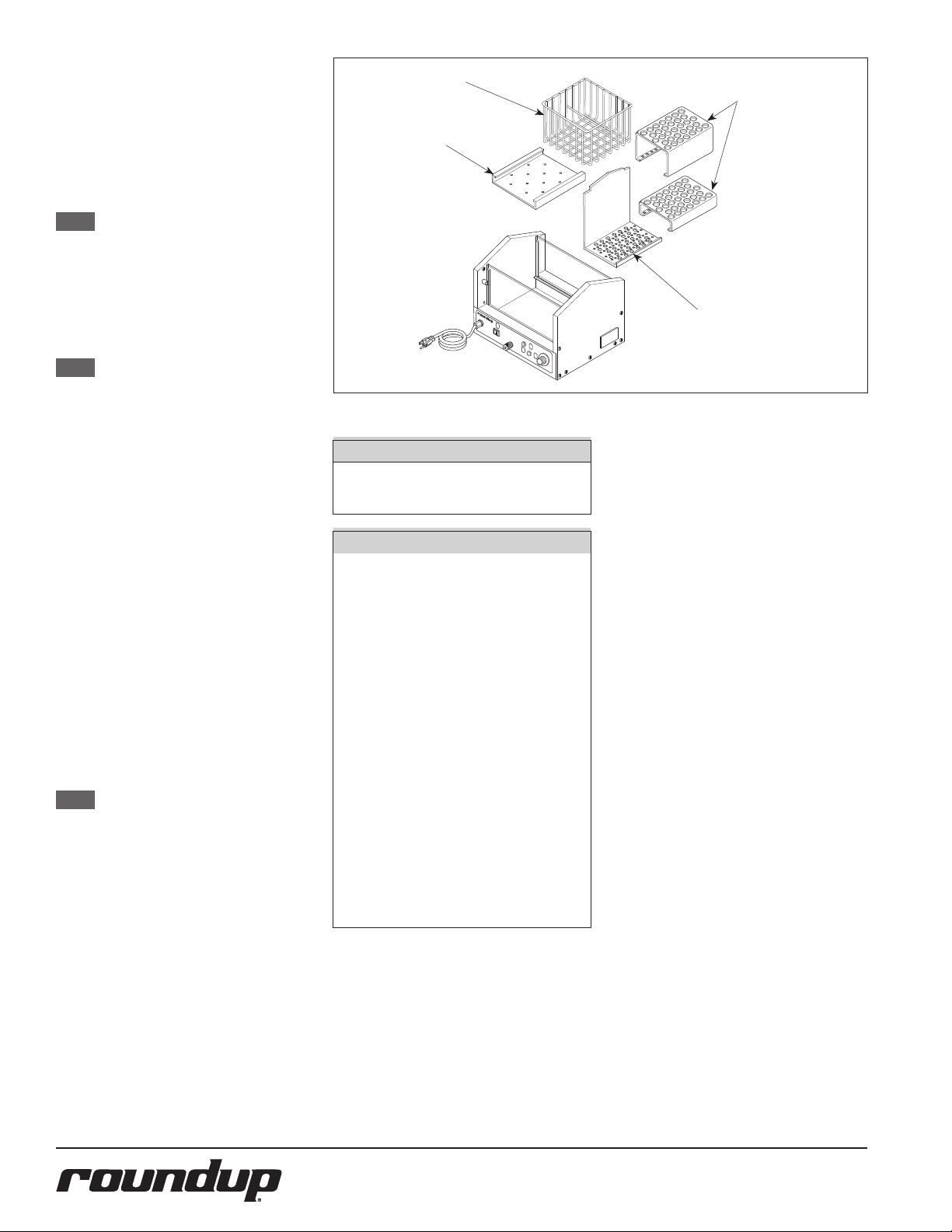
BASKET
TR AY
Figure 1. Hot Dog Hutch Components (HDH-3 Shown)
CAUTION
All electrical connections must be in
accordance with local electrical codes
and any other applicable codes.
WARNING
y ELECTRICAL SHOCK HAZARD.
Failure to follow the instructions in this manual could result
in serious injury or death.
y Electrical ground is re-
quired on this appliance.
y Do NOT modify the power sup-
ply cord plug. If it does not t
the outlet, have a proper outlet
installed by a qualied electrician.
y Do NOT use an exten-
sion cord with this unit.
y The unit should be grounded ac-
cording to local electrical codes to
prevent the possibility of electrical shock. It requires a grounded
receptacle with separate electrical
lines, protected by fuses or circuit
breaker of the proper rating.
y Check with a qualied electrician
if you are unsure if the appliance is properly grounded.
RACKS
BULKHEAD
6
P/N 1010736 Rev. G 05/14
Page 7

OPERATING
INSTRUCTIONS
1. Remove, or slide open, the top cover.
2. Pour 7 quarts (5.6 liters) of clean tap
water into the water pan (Figure 2).
There is a “FULL” line inscribed on the
inside of the pan.
CAUTION
Do NOT pour water hotter than 120°F
(48°C) into a cold unit. Resulting
steam can cause personal injury.
NOTE: Using hot water will shorten the
time it takes for the unit to reach
operating temperature.
3. Load the unit with product and
install or close the cover.
4. Turn the rocker switch (power on/
off) to the ON position.
5. Turn the thermostat knob fully clockwise (maximum heat) and indicator
light will come on. When temperature setting is reached, heat indicator
light will go out.
6. The water will begin to steam in approximately 30-40 minutes (or sooner if hot water was used initially). The
product will be thoroughly heated
and ready to serve 15-20 minutes
after steaming begins.
7. When the product is ready to be
served, turn the thermostat knob to
180°F (82°C) to maintain the food at
serving temperature.
NOTE: Volume, preference and experi-
ence will determine what temperature setting is best for your
operation.
8. To remove product from the unit,
lift one side of the top cover and let
it rest in the upright position. Using
tongs or a similar utensil, lift the
product out and close the cover.
NOTE: Keep cover closed unless adding
or removing product.
WARNING
Keep face away from cover and opening
when removing product from unit. Steam
can escape and cause personal injury.
For MFg. No. 9300132
the power cord is located
on the left side of the
unit. See Note on Page
11.
Figure 2. Filling Water Tray
ROCKER SWITCH
HILIMIT RESET SWITCH
“HEATER ON”
INDICATOR LIGHT
THERMOSTAT CONTROL
Figure 3. Controls
Hi-Limit Reset Button
A hi-limit thermostat will turn off electrical
power to the heater and control circuits
if the unit overheats due to running low
on water. To reset this thermostat, allow
sufficient time (10-15 minutes) for the unit
to cool down, then press the Hi-Limit Reset
Button located on the front of the unit
(Figure 3).
If the unit requires continuous resetting,
contact your Roundup Authorized Service
Agency.
P/N 1010736 Rev. G 05/14
7
Page 8

MAINTENANCE
CAUTION
Chlorides or phosphates in cleaning agents (e.g. bleach, degreasers or
detergents) could cause permanent
damage to stainless steel equipment.
The damage is usually in the form of
discoloration, dulling of metal surface
nish, pits, voids, holes or cracks. This
damage is permanent and NOT covered
by warranty. The following tips are
recommended for maintenance of your
stainless steel equipment:
y Always use soft, damp cloth
for cleaning, rinse with clear
water and wipe dry. When
required, always rub in direction of metal polish lines.
y Routine cleaning should be
done daily using soap, ammonia detergent and water.
y Stains and spots should be re-
moved using a vinegar solution.
y Finger marks and smears should
be removed using soap and water.
y Hard water spots should be re-
moved using a vinegar solution.
WARNING
Turn the power o, unplug the power cord,
and allow the unit to cool down before
performing any service or maintenance.
WARNING
Do NOT use abrasive cleansers or materi-
als. The use of these may cause dam-
age to the stainless steel nish.
DAILY CLEANING
The unit requires a minimum amount of
maintenance. To ensure proper operation,
clean the unit at the end of each serving
day.
1. Turn the thermostat knob fully counterclockwise to the off position.
2. Unplug the power cord from the
electrical outlet and allow the unit
to cool to room temperature before
proceeding.
3. Remove and wash the Baskets, Racks,
and Support Trays in soap and water.
Then rinse and wipe dry.
WATER DRAIN CAP
WITHOUT CHAIN
Figure 4. Draining Water from the Unit
WARNING
Draining water while the unit is hot
may result in personal injury.
4. Remove the Drain Cap (Figure 4) and
allow all water to drain from the unit.
5. Use a towel or heavy cloth to remove
any remaining water from the pan,
then wash and wipe dry.
6. Wash glass surfaces, inside and out,
with a clean cloth.
7. Wash and dry all surfaces of the unit.
8. Re-instal all parts.
NOTE: Failure to properly clean and dry
the above items prior to reassembly may result in the accumulation of moisture overnight. This
may lead to permanent damage
of the equipment’s nish and
accessories. This damage is NOT
covered by
warranty.
8
P/N 1010736 Rev. G 05/14
Page 9

TROUBLESHOOTING
To avoid possible personal injury and/or damage to the unit, inspection, test and repair of electrical equip-
ment should be performed by qualied service personnel. The unit should be unplugged when servicing.
Problem Possible Cause Corrective Action
Unit will not heat. Heat Indicator Light does not
turn on.
No heat or insufficient heat. Heat Indicator Light is
on.
Water continues to boil after Temperature Control
Knob is set to low temperature.
WARNING
No power. Check that the power cord is plugged into
the appropriate outlet. Check fuse or circuit
breaker.
Inoperable outlet. Plug power cord into another appropriate
outlet.
Hi-Limit Thermostat is tripped. Reset Hi-Limit Thermostat.
Inoperable Hi-Limit Thermostat. Replace Hi-Limit Thermostat.
Inoperable power cord or plug. Replace power cord.
Inoperable Thermostat. Replace Thermostat.
Inoperable Power Switch Replace Power Switch
Inoperable Heating Element. Replace Heating Element.
Inoperable Thermostat. Replace Thermostat.
Inoperable Thermostat. Replace Thermostat.
P/N 1010736 Rev. G 05/14
9
Page 10

LIGHT
WIRING DIAGRAM
10
P/N 1010736 Rev. G 05/14
Page 11

INSET
15
16
14
13
12
30
2
33
1
17
29
34
7
33
20
5
4
3
37
11
36
37
33
9
8
10
34
31
35
19
32
22
23
21
24
33
18
25
HDH-3
36
6
38
REPLACEMENT PARTS
NOTE: Item 1 for Mfg. No.
9300132 uses a dierent Left Side Panel than
other units contained
in this manual. This allows the power cord for
9300132 to be located on
the Left side of the unit
rather than on the front
of the unit. The new Left
Side Panel part numbers
is 0506673.
P/N 1010736 Rev. G 05/14
11
Page 12

REPLACEMENT PARTS
Item Part No. Description Qty.
1 0010896 Pan Housing Assy. (HDH-3 Series) 1
0012923 Pan Housing Assy. 1
(Mfg. No. 9300132 ONLY)
2 403K111 Thermostat Kit °F 1
7000887 Thermostat Kit °C 1
3 4030230 Heating Element, 120V 1
4030234 Heating Element, 230V 1
4 0500556 Retainer, Heating Element 2
5 0020973 Base Plate Weldment 1
6 0011652 Drain Cap Assy. 1
6a 0020282 Drain Cap Assy. with chain (not shown) 1
7 210K230 Bumper, 1” Leg Kit (set of 4) 1
8 0501700 Bracket, Hi-Limit Thermostat 1
9 4030291 Thermostat, Hi-Limit 1
10 0501768 Retainer Cap, Bulb 1
11 0502160 Plate, Diuser 1
12 2100144 Knob, Thermostat (F°) 1
2100226 Knob, Thermostat (C°) 1
13 4060323 Indicator Light, 120V 1
4060229 Indicator Light, 230V 1
Item Part No. Description Qty.
14 7000882 Power Swich Replacement Kit 1
15 0700463 Power Cord, NEMA 5-15P, 120V 1
(Mfg. No. 9300100, 104, 118, 106,
112, 120, 124, & 132)
0700453 Power Cord, CEE 7/7, 230V 1
(Mfg. No. 9300101, 102, 116,
108, & 125)
0700354 Power Cord, Australia 1
(Mfg. No. 9300130)
16 040K251 Strain Relief Kit 1
17 0900200 Glass Panel 2
0506674 Aluminum Panel 2
(Mfg. No. 9300132 ONLY)
18 0501678 Retainer, Upper Glass 2
19 7000136 Terminal Block Kit 1
(Incl. #31 & 32)
20 0400240 Insulation 1
21 0010897 Top Cover Assy. (Incl. #22, 23, 25) 1
(HDH-3 Series) 1
Item Part No. Description Qty.
22 2100145 Knob, Cover 4
23 7000166 Guard, Finger (Incl. #24 & 25) 4
24 310P177* Stud, #10-32 x 5/8” 1
25 0503383 Spacer, Finger Guard 4
29 212P140* Spacer, Round (HDH-3 Series) 1
30 306P104* Screw, #6-32 x 1/4” 1
31 306P123* Screw, #6-32 x 7/8” 1
32 306P130* Nut, Hex, KEPS, #6-32 1
33 308P103* Screw #8-32 x 1/4” 30
34 308P105* Screw, #8-32 x 1/2” 5
35 308P143* Nut, Hex, KEPS, #10-32 2
36 310P140* Washer, #10 24
37 310P146* Nut, Hex, KEPS, #10-32 13
38 1000913 Label, Control 1
1001524 Label, Control 1
(Mfg. No. 9300132 ONLY)
39 0700488 Wire Set (not shown) 1
* Only available in packages of 10.
12
P/N 1010736 Rev. G 05/14
Page 13

REPLACEMENT PARTS
HDH-3 Racks & Baskets
1 P/N 0501687
1 P/N 0506677
3
5
4
Item Part No. Description Qty.
1 0501687 Support Tray (not included in 7000945) 1
0506677 Support Tray (included in 7000945) 1
3 0501749 Hot Dog Rack, Upper 1
2 0501750 Bulkhead 1
4 0501776 Hot Dog Rack, Lower 1
5 0800223 Bun Basket 1
6 7000945 Hot Dog and Bun Rack Kit 1
(Not Shown)
(Includes all items above except 0501687)
2
NOTE: These accessories are
for HDH-3 models with
Manufacturing Numbers:
9300100
9300101
9300102
9300104
9300116
9300118
P/N 1010736 Rev. G 05/14
13
Page 14

REPLACEMENT PARTS
HDH-3DR Racks
NOTE: DR = Double Racks.
3
2
3
1
2
Item Part No. Description Qty.
1 0502832 Bulkhead 2
2 0501963 Hot Dog Rack, Lower 2
3 0501962 Hot Dog Rack, Upper 2
1
NOTE: These accessories are for
HDH-3DR models with
Manufacturing Numbers:
9300106
9300108
9300120
9300124
9300132
14
P/N 1010736 Rev. G 05/14
Page 15

REPLACEMENT PARTS
HDH-3DR
(Mfg. # 9300112 ONLY)
3
NOTE: These
items are
for Jumbo
Hot Dogs.
2
3
Item Part No. Description Qty.
1 0501750 Bulkhead 2
2 0502863 Rack, Jumbo Dog, Lower 2
3 0502864 Rack, Jumbo Dog, Upper 2
1
2
NOTE: These accessories are for
HDH-3DR models with
Manufacturing Number
9300112 ONLY.
P/N 1010736 Rev. G 05/14
15
Page 16

REPLACEMENT PARTS
HDH-3DR
(Mfg. # 9300125 ONLY)
6
5
4
3
2
1
Item Part No. Description Qty.
1 0501750 Bulkhead 1
2 0501749 Upper Hot Dog Rack (Small) 1
3 0501776 Lower Hot Dog Rack (Small) 2
4 0501687 Suppor t Tray 1
5 0501962 Upper Hot Dog Rack (Large) 1
6 0501963 Lower Hot Dog Rack (Large) 1
NOTE: These accessories are for
HDH-3DR models with
Manufacturing Number
9300125 ONLY.
16
P/N 1010736 Rev. G 05/14
Page 17

NOTES
P/N 1010736 Rev. G 05/14
17
Page 18

NOTES
18
P/N 1010736 Rev. G 05/14
Page 19

NOTES
P/N 1010736 Rev. G 05/14
19
Page 20

LIMITED WARRANTY
Equipment manufactured by Roundup Food Equipment Division of A.J. Antunes & Co. has been constructed of the finest
materials available and manufactured to high quality standards. These units are warranted to be free from electrical and
mechanical defects for a period of one (1) year from date of purchase under normal use and service, and when installed in
accordance with manufacturer’s recommendations. To insure continued operation of the units, follow the maintenance
procedures outlined in the Owner’s Manual. During the first 12 months, electro-mechanical parts, non-overtime labor,
and travel expenses up to 2 hours (100 miles/160 km), round trip from the nearest Authorized Service Center are covered.
1. This warranty does not cover cost of installation, defects caused by improper storage or handling prior to placing
of the Equipment. This warranty does not cover overtime charges or work done by unauthorized service agencies
or personnel. This warranty does not cover normal maintenance, calibration, or regular adjustments as specified
in operating and maintenance instructions of this manual, and/or labor involved in moving adjacent objects to
gain access to the equipment. This warranty does not cover consumable/wear items. This warranty does not cover
damage to the Load Cell or Load Cell Assembly due to abuse, misuse, dropping of unit/shock loads or exceeding
maximum weight capacity (4 lbs). This warranty does not cover water contamination problems such as foreign
material in water lines or inside solenoid valves. It does not cover water pressure problems or failures resulting
from improper/incorrect voltage supply. This warranty does not cover Travel Time & Mileage in excess of 2 hours
(100 miles/160 km) round trip from the nearest authorized service agency.
2. Roundup reserves the right to make changes in design or add any improvements on any product. The right is always reserved to modify equipment because of factors beyond our control and government regulations. Changes
to update equipment do not constitute a warranty charge.
3. If shipment is damaged in transit, the purchaser should make a claim directly upon the carrier. Careful inspection should be made of the shipment as soon as it arrives and visible damage should be noted upon the carrier’s
receipt. Damage should be reported to the carrier. This damage is not covered under this warranty.
4. Warranty charges do not include freight or foreign, excise, municipal or other sales or use taxes. All such freight
and taxes are the responsibility of the purchaser.
5. This warranty is exclusive and is in lieu of all other warranties, expressed or implied, including any implied warranty
or merchantability or fitness for a particular purpose, each of which is hereby expressly disclaimed. the remedies
described above are exclusive and in no event shall roundup be liable for special consequential or incidental damages for the breach or delay in performance of this warranty.
 Loading...