

Page 1
MANUFACTURING
NUMBERS:
9210200
9210201
9210202
9210203
9210208
9210210
9210213
9210215
9210217
9210400
9210401
9210410
VERTICAL CONTACT
ITS
Testing & Certification
geprufte
Sicherheit
P/N 1010840 Rev. M 07/14
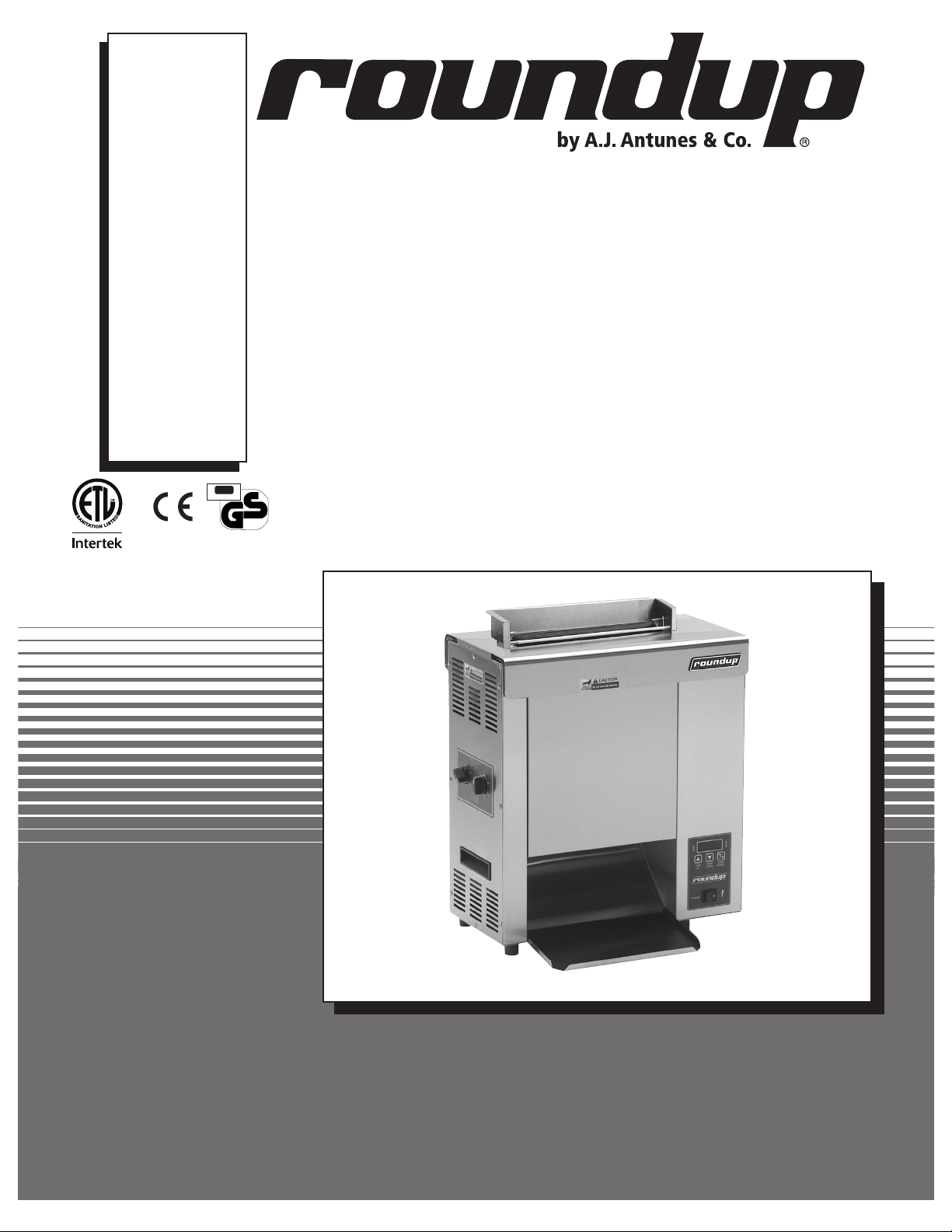
TOASTER
Model VCT-2000
Owner’s Manual
Page 2
VERTICAL CONTACT TOASTER
TABLE OF CONTENTS
Owner information .....................................................2
Warranty Information .................................................2
Service/Technical Assistance ....................................3
Important safety information ..................................... 3
Specifications .............................................................5
Electrical Specifications .............................................5
Dimensions ................................................................5
Electrical Cord and Plug Configurations ...................5
Installation ...................................................................6
Unpacking ..................................................................6
Equipment Setup .......................................................6
Assembling the Unit ..................................................6
Operation .....................................................................8
Operating Instructions ...............................................8
Temperature Adjustments ..........................................8
OWNER INFORMATION
General
Safety Features .......................................................10
Fault messages .......................................................11
Maintenance ..............................................................12
Daily .........................................................................12
Replacing the Black and Silver Release Sheet (Every
4–6 weeks) ..............................................................13
Replacing Belt Wraps (Every 3–6 months) .............13
Conveyor Belt Chains (Every 3–6 months) .............14
Roller Tensioners (Every 3–6 months) ....................15
Troubleshooting .......................................................16
Replacement Parts ...................................................20
Wiring Diagram .........................................................26
Limited Warranty ......................................................28
Warranty Information
The Vertical Contact Toaster Model VCT-2000 is
designed for contact toasting of buns. The toaster
design allows the operator to place buns on both
sides of the heated platen at the same time. Buns are
placed into the top of the toaster and uniform, golden
brown, warm buns are then retrieved at the base of the
toaster.
This manual provides the safety, installation, and
operating procedures for the Vertical Contact Toaster
Model VCT-2000. We recommend that all information
contained in this manual be read prior to installing and
operating the unit.
Your Vertical Contact Toaster Model VCT-2000 is
manufactured from the finest materials available and is
assembled to Roundup’s strict quality standards. This
unit has been tested at the factory to ensure dependable trouble-free operation.
Please read the full text of the Limited Warranty in this
manual.
If the unit arrives damaged, contact the carrier immediately and file a damage claim with them. Save all
packing materials when filing a claim. Freight damage
claims are the responsibility of the purchaser and are
not covered under warranty.
The warranty does not extend to:
• Damages caused in shipment or damage as
result of improper use.
• Installation of electrical service.
• Normal maintenance as outlined in this manual.
• Malfunction resulting from improper maintenance.
• Damage caused by abuse or careless handling.
• Damage from moisture into electrical
components
• Damage from tampering with, removal of, or
changing any preset control or safety device.
IMPORTANT! Keep these instructions for future reference. If the unit changes
ownership, be sure this manual accompanies the equipment.
2
P/N 1010840 Rev. M 07/14
Page 3
VERTICAL CONTACT TOASTER
OWNER INFORMATION (continued)
Service/Technical Assistance
If you experience any problems with the installation
or operation of your unit, contact your local Roundup
Authorized Service Agency.
Fill in the information below and have it handy when
calling your Authorized Service Agency for assistance.
The serial number is on the specification plate located
on the rear of the unit.
Purchased From:
Date of Purchase:
Model No.:
Serial No.:
Mfg. No.:
Refer to the service agency directory included with your
unit.
Authorized Service Agency
Name:
Phone No.:
Address:
Use only genuine Roundup replacement parts in this
unit. Use of replacement parts other than those supplied by the manufacturer will void the warranty. Your
Authorized Service Agency has been factory trained
and has a complete supply of parts for this toaster.
You may also contact the factory at 1-877-392-7854
(toll Free in the U.S.) or 630-784-1000 if you have trouble locating your nearest Authorized Service Agency.
IMPORTANT
A.J. Antunes & Co. reserves the right to change specifications and product design
without notice. Such revisions do NOT entitle the buyer to corresponding changes,
improvements, additions or replacements for previously purchased equipment.
IMPORTANT SAFETY INFORMATION
Throughout this manual, you will find the following safety words and symbols that signify important safety issues with
regards to operating or maintaining the equipment.
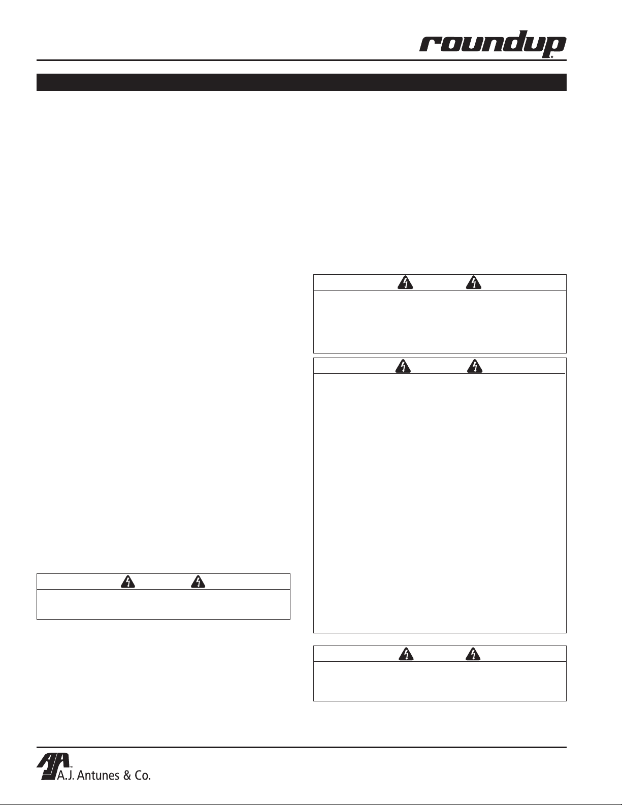
WARNING
GENERAL WARNING. Indicates information important to the proper operation of
the equipment. Failure to observe may
result in damage to the equipment and/or
severe bodily injury or death.
CAUTION
GENERAL CAUTION. Indicates information important to the proper operation of
the equipment. Failure to observe may
result in damage to the equipment.
ELECTRICAL WARNING. Indicates information relating to possible shock hazard.
Failure to observe may result in damage
to the equipment and/or severe bodily
injury or death.
HOT SURFACE WARNING. Indicates
information important to the handling of
equipment and parts. Failure to observe
caution could result in personal injury.
WARNING
WARNING
P/N 1010840 Rev. M 07/14
3
Page 4

VERTICAL CONTACT TOASTER
IMPORTANT SAFETY INFORMATION (continued)
In addition to the warnings and cautions in this manual,
use the following guidelines for safe operation of the
unit.
• Read all instructions before using equipment.
• For your safety, the equipment is furnished with
a properly grounded cord connector. Do NOT
attempt to defeat the grounded connector.
• Install or locate the equipment only for its intended use as described in this manual. Do NOT use
corrosive chemicals in this equipment.
• Do NOT operate this equipment if it has a damaged cord or plug, if it is not working properly, or
if it has been damaged or dropped.
• This equipment should be serviced by qualified
personnel only. Contact the nearest Authorized
Service Agency for adjustment or repair.
• Do NOT block or cover any openings on the unit.
• Do NOT immerse cord or plug in water.
• Keep cord away from heated surfaces.
• Do NOT allow cord to hang over edge of table or
counter.
• Bread may burn. Therefore toasters must
not be used near or below curtains or other
combustible walls and materials. Failure to
maintain safe operating distances may cause
discoloration or combustion.
• When installing the conveyor Belt Wrap, be
careful not to wrap it around the upper and
lower support rods or permanent damage to
belt will occur. Make sure the Belt Wrap is
positioned between the upper and lower
support rods.
• Make sure both ends of Belt Wrap are aligned
evenly before installing Belt Wrap Pin.
• Failure to use Release Sheets may result in
damage to the equipment and loss of warranty coverage.
• Do NOT clean this appliance with a water jet.
• If supply cord is damaged, it must be replaced
by the manufacturer or its service agent, or a
similarly qualified person.
• All electrical connections must be in accordance with local electrical codes and any
other applicable codes.
The following warnings and cautions appear
throughout this manual and should be carefully
observed.
• Turn the power off, unplug the power cord,
and allow unit to cool down before performing
any service or maintenance.
• The toaster should be grounded according to
local electrical codes to prevent the possibility of electrical shock. It requires a grounded
receptacle with separate electrical lines protected by fuses or a circuit breaker of the
proper rating.
• WARNING, ELECTRICAL SHOCK HAZARD.
FAILURE TO FOLLOW THESE INSTRUCTIONS
COULD RESULT IN SERIOUS INJURY OR
DEATH.
- Electrical ground is required on this unit.
- Do NOT modify the power supply cord
plug. If it does not fit the outlet, have a
proper outlet installed by a qualified electrician.
- Do NOT use an extension cord with this
unit.
- Check with a qualified electrician if you are
unsure if the unit is properly grounded.
4
P/N 1010840 Rev. M 07/14
Page 5
VERTICAL CONTACT TOASTER
SPECIFICATIONS
Electrical Specifications
Model &
Mfg. No.
VCT-2000
9210200
9210201
9210202
9210203
9210208
9210210
9210213
9210215
VCT-2000
9210400
9210401
9210410
Heated Base
Volts Watts Amp. Hz.
220 - 240 3019 - 3593 13.7 - 15 50
220 - 240 3058 - 3640 13.9 - 15.2 50
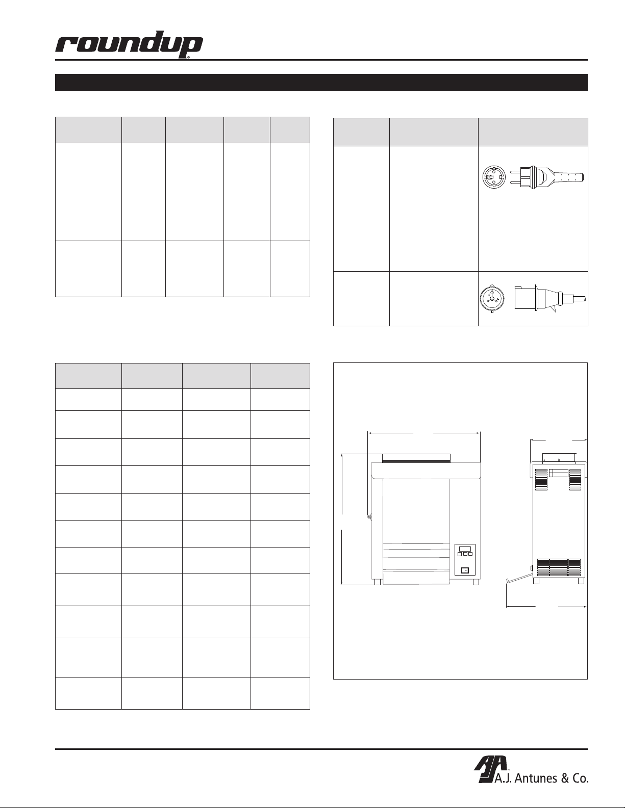
Dimensions
Model &
Mfg. No.
VCT-2000
9210200
VCT-2000
9210201
VCT-2000
9210202
Width
(A)
21 1/4"
(540 mm)
21 1/4"
(540 mm)
21 1/4"
(540 mm)
Depth
(B)
15 1/4'
(387 mm)
15 1/4'
(387 mm)
15 1/4'
(387 mm)
Height
(C)
23 1/4"
(591 mm)
23 1/4"
(591 mm)
23 1/4"
(591 mm)
Electrical Cord and Plug Configurations
Model &
Mfg. No.
VCT-2000
9210200
9210203
9210208
9210210
9210213
9210215
9210217
9210400
9210401
9210410
VCT-2000
9210201
9210202
Plug
Description
CEE 7/7, 16
Amp., 250 VAC
(Assembly Only).
IEC-309, 16 Amp.,
250 VAC.
Pin & Sleeve
(Assembly Only).
A
Plug
Configuration
B
(no bun chute)
VCT-2000
9210203
VCT-2000
9210208
VCT-2000
9210210
VCT-2000
9210213
VCT-2000
9210215
VCT-2000
9210217
VCT-2000
9210401
9210400 Heated
Base
VCT-2000
9210410 Heated
Base
21 1/4"
(540 mm)
21 1/4"
(540 mm)
21 1/4"
(540 mm)
21 1/4"
(540 mm)
21 1/4"
(540 mm)
21 1/4"
(540 mm)
21 1/4"
(540 mm)
21 1/4"
(540 mm)
P/N 1010840 Rev. M 07/14
15 1/4'
(387 mm)
15 1/4'
(387 mm)
15 1/4'
(387 mm)
15 1/4'
(387 mm)
15 1/4'
(387 mm)
15 1/4'
(387 mm)
10 3/4'
(273 mm)
10 3/4'
(273 mm)
24 1/4"
(616 mm)
23 1/4"
(591 mm)
23 1/4"
(591 mm)
23 1/4"
(591 mm)
23 1/4"
(591 mm)
23 1/4"
(591 mm)
23 1/4"
(591 mm)
23 1/4"
(591 mm)
C
B
5
Page 6
VERTICAL CONTACT TOASTER
INSTALLATION
Unpacking
1. Remove the unit and all packing materials from
shipping carton.
2. Open the included large box. It should contain the
following:
• Bun Chute (Figure 1) some models only.
• Bun Feeder (Figure 1) some models only.
• Two Release Sheets (Figure 1).
• Owner’s Manual.
• Maintenance Card (some models only).
• Authorized Service Agency Directory.
3. Remove all shipping tape and protective coverings from the unit and parts.
NOTE: If any parts are missing or damaged, contact Antunes Technical Service IMMEDIATELY at 1877-392-7854 (toll free in the U.S.) or 630-784-1000.
Equipment Setup
Before placing the toaster into service, pay attention to
the following guidelines:
• Make sure power to the unit is off and the toaster
is at room temperature.
Assembling the Unit
NOTE: The factory has pre-installed a Release
Sheet over the Platen (Figure 1). Verify that it is
properly in place before proceeding.
1. Remove Bun Chute (some models) and Bun
Feeder from the box and install (Figure 1).
IMPORTANT: Make sure heat shield assembly is
activating the Conveyor Safety Interlock Switch
(see Figure 1). The conveyors will not rotate unless
the Heat Shield is in place and Conveyor Safety
Interlock Switch is activated.
CAUTION
Bread may burn. Therefore toasters must not be
used near or below curtains or other combustible
walls and materials. Failure to maintain safe operating distances may cause discoloration or combustion.
WARNING
ELECTRICAL SHOCK HAZARD. FAILURE TO
FOLLOW THE INSTRUCTIONS IN THIS MANUAL
COULD RESULT IN SERIOUS INJURY OR DEATH.
• Electrical ground is required on this appliance.
• Do NOT block or cover any openings on the unit.
• Do NOT immerse cord or plug in water.
• Keep cord away from heated surfaces.
• Do NOT allow cord to hang over edge of table or
counter.
• Connect the unit to the proper power supply.
Refer to the specification plate for proper voltage
WARNING
Failure to use Release Sheets may result in damage to the unit and loss of warranty coverage.
• Do NOT modify the power supply cord plug. If
it does not fit the outlet, have a proper outlet
installed by a qualified electrician.
• Do NOT use an extension cord with this
appliance.
• The toaster should be grounded according to
local electrical codes to prevent the possibility of electrical shock. It requires a grounded
receptacle with separate electrical lines protected by fuses or a circuit breaker of the proper rating.
• Check with a qualified electrician if you are
unsure if the appliance is properly grounded.
CAUTION
All electrical connections must be in accordance
with local electrical codes and any other applicable codes.
6
P/N 1010840 Rev. M 07/14
Page 7
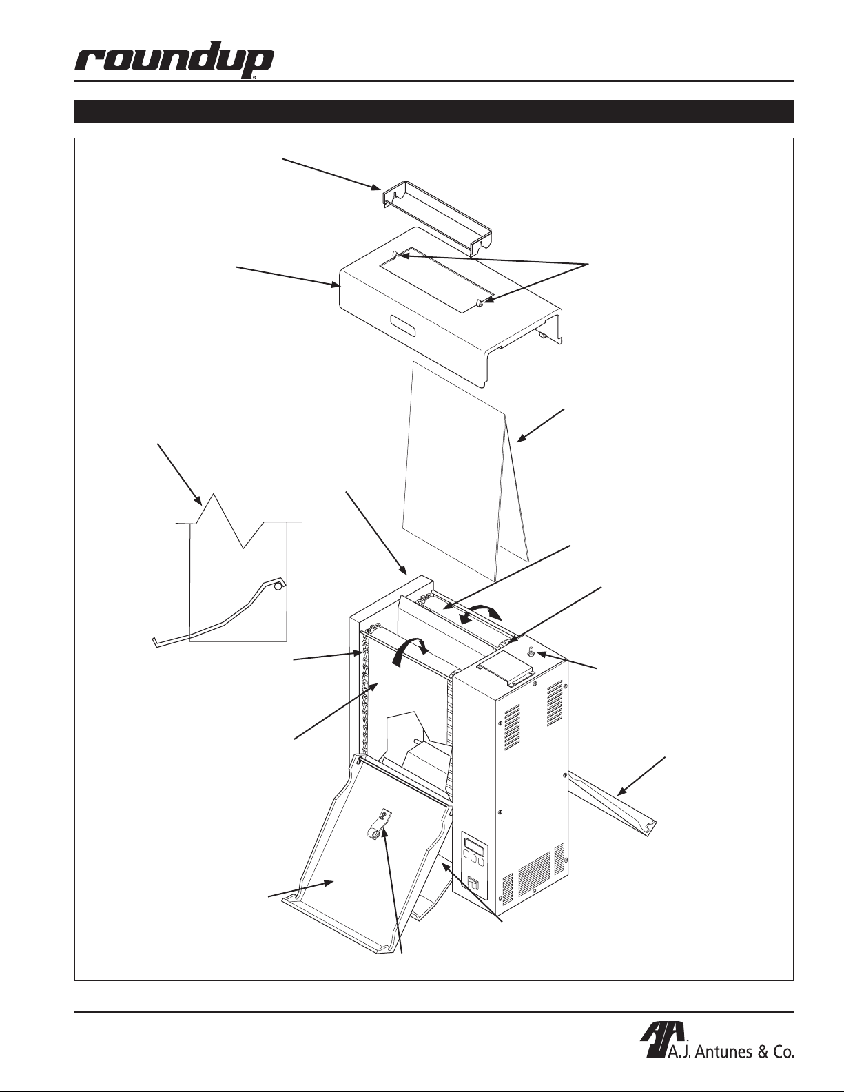
Bun Feeder
(some models only)
Heat Shield
VERTICAL CONTACT TOASTER
INSTALLATION (continued)
Release
Sheet
Retainer
Clips
Bun Chute Assembly
connected over the
bottom rear support rod
(some models only)
Front
Conveyor
Belt Chain
Front Belt
Wrap
Release
Sheet
Platen
Rear Belt
Wrap
Rear
Conveyor
Belt Chain
Conveyor
Safety
Interlock
Switch
Rear Conveyor
Cover Assembly
(with Roller Tensioner)
Front Conveyor
Cover Assembly
P/N 1010840 Rev. M 07/14
Bun Chute
(some models only)
Roller Tensioner
Figure 1. VCT-2000 Toaster
7
Page 8
VERTICAL CONTACT TOASTER
1
2
4
5
1 = 1/2"(12.7mm)
2 = 5/8"(15.9mm)
3 = 11/16"(17.5mm)
6 = 7/8"(22.2mm)
THICKNESS
THICKNESS
1
2
3
4
6
6
5
4 = 3/4"(19.1mm)
5 = 13/16"(20.6mm)
3
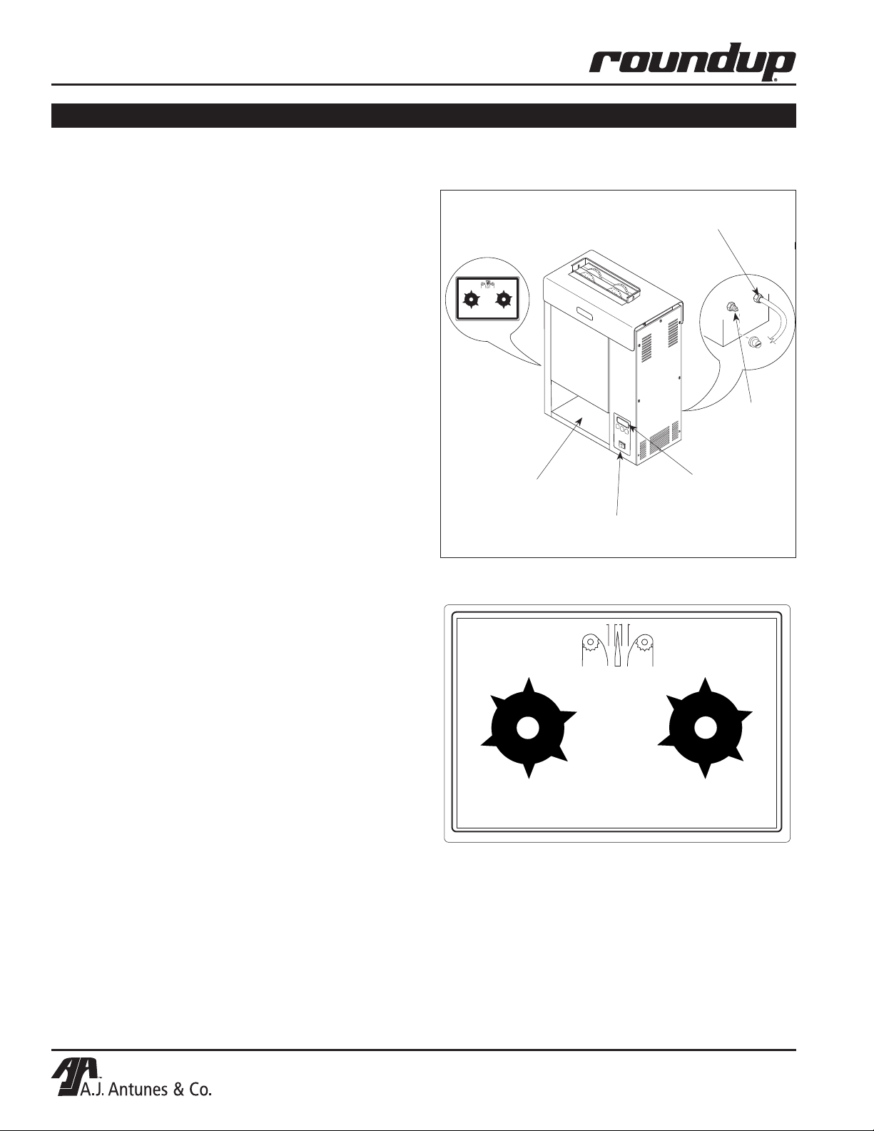
OPERATION
Operating Instructions
1. Set the Bun Thickness Adjustment Controls
(Figure 3) to desired setting.
NOTE: Recommended settings are #2 for heel and
#6 for crown.
2. Turn the Rocker Switch on. (Figure 2). Allow the
toaster to warm-up for 30 minutes before proceeding.
NOTE: The temperature display (Figure 2) will flash
“LO” until the toaster reaches its preset operating
temperature. When the toaster approaches the preset temperature of 600°F (315°C), “USE” appears
in the temperature display and the unit is ready to
toast buns. If “USE” does not appear in the window
after warm-up period of approximately 30 minutes,
contact your Authorized Service Agency.
3. Drop Crowns and Heels into the slot (Figure 2).
Cut sides of heel and crown must face each
other.
4. Toasted buns will drop into the bun landing area
(Figure 2).
NOTE: The toaster is tested and shipped with the heaters
set at the above recommended temperatures.
Bun Thickness
Adjustment Control
(See Figure 3)
Bun Landing Area
Rocker
Switch
Power
Cord
Hi-Limit
Reset
Temperature
Controls
& Temperature
Display
Figure 2. VCT-2000 Toaster
5. Test at least four buns before putting the toaster
into service.
6. Turn the Rocker Switch off when finished toasting
for the day and proceed with the Daily Cleaning
as outlined in the Maintenance section of this
manual.
Temperature Adjustments
The VCT-2000 uses a Platen Heater and two Auxiliary
Air Heaters. The Platen Heater consists of a heating
element built into the Platen to toast the cut side of
the bun. The two Auxiliary Heaters assist in providing additional heat to the buns. The first Auxiliary Air
Heater is located between the conveyor in the front
of the toaster. The second Auxiliary Heater is located
between the conveyor at the rear of the unit.
RECOMMENDED TEMPERATURES
Recommended temperature setting for the Platen heater is 600°F (315°C).
Recommended temperature setting for the Auxiliary Air
Heaters is 400°F (204°C).
THICKNESS
3
2
4
1
5
1 = 1/2"(12.7mm)
6
2 = 5/8"(15.9mm)
3 = 11/16"(17.5mm)
4 = 3/4"(19.1mm)
5 = 13/16"(20.6mm)
6 = 7/8"(22.2mm)
THICKNESS
6
5
1
4
2
3
Figure 3. Bun Thickness Adjustment Controls
8
P/N 1010840 Rev. M 07/14
Page 9
TEMP
UP
TEMP
DOWN
TEMP
SCALE
˚F
˚C
POWER
TEMP
UP
TEMP
DOWN
TEMP
SCALE
˚F
˚C
POWER
SP - P
600
TEMP
UP
TEMP
DOWN
TEMP
SCALE
˚F
˚C
POWER
TEMP
UP
TEMP
DOWN
TEMP
SCALE
˚F
˚C
POWER
400
SP - A
TEMP
UP
TEMP
DOWN
TEMP
SCALE
°F
°C
POWER
LO
USE
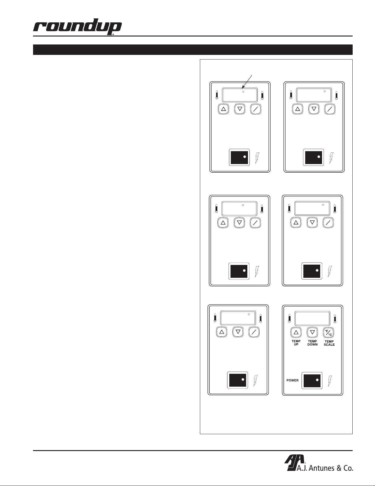
OPERATION (continued)
TEMPERATURE CONTROL PANEL
NOTE: The term “set point temperature” refers to the
desired temperature setting.
To display the actual Platen temperature—providing it is
over 440°F (227° C)—press the TEMP UP button.
To display the actual Auxiliary Air Heater temperature—
providing it is over 360°F (182°C)—press the TEMP
DOWN button.
To switch the temperature display between Fahrenheit
(°F) and Celsius (°C), press and hold the TEMP SCALE
button for 5 seconds.
PLATEN HEATER TEMPERATURE ADJUSTMENT
1. Turn the Rocker Switch on and wait for the
Temperature Display to finish the power up
sequence (Figure 4).
2. Press and hold the TEMP UP and TEMP DOWN
buttons for over 1 second until the display flashes
the Platen set point temperature, then release
(Figure 5).
VERTICAL CONTACT TOASTER
“Heat On” LED will blink on/off during warm up and when either
platen or auxiliary air heaters are calling for heat.
1. SP-P (Set Point Platen)
is displayed
2. Current Platen Set Point
Temperature setting is shown
3. Press the TEMP UP button to raise the set point
temperature or press the TEMP DOWN button to
lower the set point temperature.
NOTE: The Maximum Platen Set point Temperature
is 600°F (315°C). If no change in temperature is made
within 5 seconds, the display reverts back to the previous set point.
4. Release the button when the desired set point is
displayed.
AUXILIARY AIR HEATER TEMPERATURE ADJUSTMENT
1. Turn the Rocker Switch on and wait for Temperature
Display to finish the power up sequence (Figure 4).
2. Press and hold the TEMP UP and TEMP SCALE
buttons for over 1 second until the display flashes
the set point temperature, then release (Figure 6).
3. Press the TEMP UP button to raise the set point
temperature or press the TEMP DOWN button to
lower the set point temperature.
NOTE: The maximum Auxiliary Air Heater Set point
Temperature is 400°F (204°C).
4. Release the button when the desired set point is
displayed.
NOTE: If no change in temperature is made within 5
seconds, the display reverts back to the previous set
point.
3. SP-A (Set Point Auxiliary)
is displayed
5. “LO” is displayed until
platen temperature rises
above 550°F (288°C)
* Platen set point temperature must be between
460°F (238°C) and 600°F (315°).
4. Current Auxiliary Air Set Point
Temperature is shown
6. "USE" is displayed when
Platen Set Point Temperature*
is reached
Figure 4. Temperature Power Up Sequence
P/N 1010840 Rev. M 07/14
9
Page 10

VERTICAL CONTACT TOASTER
TEMP
UP
TEMP
DOWN
TEMP
SCALE
°F
°C
POWER
551
TEMP
UP
TEMP
DOWN
TEMP
SCALE
°F
°C
POWER
336
OPERATION (continued)
1. Press both buttons at the same
time for 1 second to start adjustment sequence.
2. Press TEMP UP button to raise
platen set point temperature.
3. Press TEMP DOWN button
to lower platen set point
temperature.
Figure 5. Platen Heater Set Point Temperature
1. Press both buttons at the same
time for 1 second to start adjustment sequence.
2. Press TEMP UP button to raise
auxiliary air heaters set point
temperature.
Safety Features
HI-LIMIT RESET BUTTON
A Hi-Limit Control turns off electrical power to the heater and control circuits if the platen overheats. To reset
the control, allow sufficient time (10-15 minutes) for the
unit to cool, then locate the Reset Button at the rear
of the unit. Remove the black protective cap, press
the Reset Button, and reinstall the protective cap
(Figure 2).
NOTE: If the unit requires continuous resetting,
contact your Authorized Service Agency.
3. Press TEMP DOWN button to
lower auxiliary air heaters
set point temperature.
Figure 6. Auxiliary Air Heaters Set Point Temperature
10
P/N 1010840 Rev. M 07/14
Page 11

VERTICAL CONTACT TOASTER
TEMP
UP
TEMP
DOWN
TEMP
SCALE
°F
°C
POWER
TEMP
UP
TEMP
DOWN
TEMP
SCALE
°F
°C
POWER
HI
USE
TEMP
UP
TEMP
DOWN
TEMP
SCALE
°F
°C
POWER
CHEC
TEMP
UP
TEMP
DOWN
TEMP
SCALE
°F
°C
POWER
PO
OPERATION (continued)
Fault messages
• If the Platen Thermocouple is disconnected or
“open”, the display will flash “HI.” The Platen
Thermocouple must be reattached or replaced.
• If the Platen Heater temperature exceeds 620°F
(327°C) the display will flash “HI” and the heating
circuit will turn off (Figure 7). After the toaster has
cooled down, the unit must be turned off, then back
on to restart. If this condition repeats, contact your
Authorized Service Agency.
• If the Auxiliary Heating temperature exceeds 420°F
(215°C) the display will alternately flash “HI” and
“USE” (Figure 7). After the toaster has cooled
down, the unit must be turned off, then back on
to restart. If this condition repeats, contact your
Authorized Service Agency.
• The temperature controller has an ambient
temperature sensor that will disable the heating
circuits if the control compartment ambient
temperature becomes excessive: 140°F (60°C)
to 180°F (82°C).
When this occurs, the temperature display will flash
“CHEC” (Figure 8). To restart the unit, ambient must
drop to 140°F (60°C) and the unit must be turned
off, then back on. If this condition repeats, contact
your Authorized Service Agency.
“HI” will flash if platen
temperature exceeds 620°F
(327°C) or if platen thermocouple is disconnected or “open”.
Figure 7. “HI” Fault Message
“CHEC” will flash when
control compartment
ambient temperature is
excessive: 140°F (60°C) to
180°F (82°C). All heaters will
shut off.
“HI” and “USE” will flash if
auxiliary heaters temperature
exceeds 440°F (227°C) or if
the Auxiliary Thermocouple
is disconnected or “open.”
• If incoming power drops below 175 Volts, the heating circuits are disabled and the display will read
“PO” (Figure 9). To reset, the voltage must be over
190 Volts, then the unit must be turned off and back
on. If this condition repeats, contact your Authorized
Service Agency.
• The “PH” fault message (Figure 9) is displayed if
the Conveyor Interlock Safety Switch (Figure 1)
is not properly engaged . When a PH fault exists,
reposition the Heat Shield so that it fully engages
the Conveyor Safety Interlock Switch. The unit
should return to normal operation when the Heat
Shield is positioned correctly.
If the “PH” Fault does not clear, contact your
Authorized Service Agency for service.
Figure 8. “CHEC” Fault Message
“PO” will flash if
incoming power drops below
190 Volts. Toaster shuts
down.
“PH” will flash when the
Conveyor Safety Interlock
Switch is not properly
engaged.
TEMP
UP
POWER
Figure 9. “PO” and “PH” Fault Messages
ph
TEMP
DOWN
°F
°C
TEMP
SCALE
P/N 1010840 Rev. M 07/14
11
Page 12

VERTICAL CONTACT TOASTER
MAINTENANCE
WARNING
Turn the power off, unplug the power cord, and
allow the unit to cool down 30 minutes before
performing any service or maintenance.
CAUTION
To prevent damage to the unit, do NOT use abrasive cleaners on the Release Sheet or Belt Wrap.
CAUTION
Failure to use Release Sheets may result in damage to the unit and loss of warranty coverage.
Daily
CLEANING THE BLACK AND SILVER RELEASE SHEET,
CONVEYOR BELT WRAPS, AND TOASTER
Tools Required:
• Heat-resistant gloves
• Clean towels
• Multipurpose Detergent Solution
• Sanitizer Solution
1. Turn the Rocker Switch off, unplug the power
cord, and allow the unit to cool for 30 minutes.
2. Put on heat-resistant gloves. Remove the Bun
Feeder, Heat Shield, and Bun Chute (some models). Wipe them with a damp sanitized towel and
allow them to air dry.
3. Remove the Release Sheet and place it on a
clean, flat dry surface. Wipe the silver side with
a clean towel dampened with Multipurpose
Detergent Solution immediately followed by a
second clean towel dampened with sanitizer and
allow it to air dry before continuing. Repeat this
step on the black side of the Release Sheet once
the silver side is dry.
4. Open the front Conveyor Cover and firmly wipe
the black Belt Wrap from left to right and top
to bottom with a clean towel dampened with
Multipurpose Detergent Solution immediately
followed by a second clean towel dampened with
sanitizer.
6. Close the rear Conveyor Cover, reinstall the Heat
Shield, plug in the power cord, turn the unit on,
until the uncleaned portion of the Belt Wrap is
accessible. Then turn the unit off and unplug the
unit.
7. Remove the Heat Shield, then open the rear
Conveyor Cover and clean the newly exposed
section of the Belt Wrap in the same manner as
before. Close the Conveyor Cover.
8. Open the front Conveyor Cover again and clean
the newly exposed section of the Belt Wrap in the
same manner as before.
9. Close the front Conveyor Cover and wipe down
the outside of the toaster with a clean, damp,
sanitized towel.
10. Install the Release Sheet by draping it over both
sides of the Platen with the crease centered on
the Platen.
NOTE: Rotate from the black side to the silver side
daily or weekly to prolong the life of the Release
Sheet.
11. Install the Bun Chute so the hooks are installed
over the lower rear yellow Support Rod. Install
the Heat Shield with the Release Sheet Retainer
clips securely over the Release Sheet and
Platen.
12. Reinstall the Bun Feeder and plug in the unit.
NOTE: Make sure the Heat Shield is activating the
Conveyor Safety Interlock Switch. The Conveyors
will not rotate unless the Heat Shield is in place
and the Conveyor Safety Interlock Switch is activated.
NOTE: Check the Release Sheet to make sure it is
not caught in the Conveyor. Additional Release
Sheets can be obtained through your Authorized
Service Agency under P/N 7000249 (3-Pack) or
7000250 (10-Pack).
5. Close the front Conveyor Cover, open the rear
Conveyor Cover, and clean the Belt Wrap as
described in Step 4.
12
P/N 1010840 Rev. M 07/14
Page 13

VERTICAL CONTACT TOASTER
CAUTION
INCORRECT
CORRECT
MAINTENANCE (continued)
Replacing the Black and Silver Release
Sheet (Every 4–6 weeks)
NOTE: Depending on toaster usage and on how
well it is cleaned daily, the black and silver Release
Sheet should last 45 to 60 days.
1. Remove and discard the Release Sheet.
2. Lay a new Release Sheet on a clean, dry surface
and fold it in half lengthwise and gently crease it
at the fold using only your fingers.
3. Install the Release Sheet.
Fold over so
ends meet.
Press Lightly
with finger to
form crease.
Replacing Belt Wraps (Every 3–6 months)
NOTE: Depending on toaster usage and how well
they are cleaned daily, the black Belt Wraps should
last 3 to 6 months. Additional Belt Wraps may be
purchased from your Authorized Service Agency.
Conveyor
Cover Assy.
Figure 11. Removing Belt Wrap
Upper Support Rod
Lower
Support Rod
Conveyor Belt
Chains
Conveyor
Safety
Interlock
Switch
Belt Wrap
Belt Rotation
Belt Wrap
Pin
Pin
1. Turn the Rocker Switch off, unplug the power
cord, and allow the unit to cool.
2. Remove the Bun Feeder and Heat Shield and set
the Compression Control Knobs to 6 and 6.
3. Open both Conveyor Covers and pull the Belt
Wrap Pin out of the “zipper” (Figure 11).
4. Remove and discard the old Belt Wrap(s).
5. Clean both Conveyor Belt Chains just as you
would clean the Belt Wraps during daily cleaning
(Figure 11).
6. Install the new Belt Wrap(s) around the Conveyor
Belt Chains inside the yellow rods with the “zipper” flap exposed and hanging down (Figures 12
& 13).
7. Close the Conveyor Cover(s), set the
Compression Control Knobs back to their normal
settings and reinstall the Heat Shield and Bun
Feeder.
Figure 12. Installing Belt Wrap
Figure 13. Aligning Belt Teeth
CAUTION
Align the ends of the Belt Wrap properly (Figure
13) or the Belt Wrap may be damaged. Position
the Belt Wrap between the upper and lower yellow
support rods or damage to the unit may occur.
P/N 1010840 Rev. M 07/14
13
Page 14

VERTICAL CONTACT TOASTER
MAINTENANCE (continued)
WARNING
Turn the power off, unplug the power cord and
allow the unit to cool down before performing any
service or maintenance.
Conveyor Belt Chains (Every 3–6 months)
MEASURING CONVEYOR BELTS CHAINS
Facing the toaster, locate the approximate center point
of the Conveyor Chain. Pull the Conveyor Chain away
from the edge of the toaster. Stand a U.S. Dime,
11/16” (1.8 cm) coin on end between the frame and the
chain. If the gap is significantly wider than the coin,
REMOVE links as described below. Then, measure
the gap again to make sure it is not too tight. Check
the opposite side of the toaster using the same measurements.
4. Reassemble the Conveyor Belt Chain onto the
sprockets as described below.
NOTE: If the belt is too short to be reassembled,
remove an additional 1/2” small link and install a
3/4” large link. This will shorten the belt 1/4”.
REPLACING CONVEYOR BELT CHAINS
1. Remove the old Conveyor Belt Chain as
described in the previous steps.
2. Place the replacement Conveyor Belt Chain on
the top sprockets with hook ends down. Check for
correct positioning (Figure 14).
NOTE: The ends of the hooks must point down.
(Figure 14).
3. Wrap the Conveyor Belt Chain around lower
sprockets and connect by hooking both ends
together.
NOTE: Make sure the Conveyor Belt Chain is
installed under the Upper Support Rod and over the
Lower Support Rod.
ADJUSTING CONVEYOR BELT CHAINS
After a time, the Conveyor Chain links will wear and
the Conveyor Belt chain will stretch, eventually skipping
on the sprockets. This is easily remedied by removing
one or more conveyor links from each side of the belt.
There are two 1/2” small links on each side of the conveyor belt. The others are large, 3/4” long (Figure 14).
REMOVING CONVEYOR BELT CHAINS
1. Perform steps 1 - 4 under Replacing Belt Wraps
on the previous page.
2. Disconnect the Conveyor Belt Chain by squeezing any two links together and unhooking both
ends of one link (Figure 14).
3. To shorten a stretched Conveyor Belt Chain,
remove one 1/2” link from the belt.
Rotation
Upper Support Rod
Large Link
P/N 0800121
Small Link
P/N 0800204
Figure 14. Removing Conveyor Belt Chains
14
P/N 1010840 Rev. M 07/14
Page 15

VERTICAL CONTACT TOASTER
MAINTENANCE (continued)
Roller Tensioners (Every 3–6 months)
MEASURING ROLLER TENSIONERS
1. Measure the Roller Tensioner on both inner
Conveyor Covers (See illustration). Adjust or
replace any damaged ones as recommended.
The space between the inner Conveyor Cover
and bottom of the tensioner wheel should be
13/16” (2.1 cm) or the height of a U.S. Nickel.
Figure 15. Measuring Roller Tensioner
REPLACING ROLLER TENSIONERS
1. Remove the acorn nuts and old Roller Tensioner
assembly (Figure 15).
2. Replace Roller Tensioner assembly, and reassemble.
3. Make sure the spacers are placed inside the
tensioner arm. The spacers are smaller than the
holes to allow the tensioner to pivot freely.
Acorn Nuts
Tensioner
Assy.
Weld
Screws
Spacers
Tape
Figure 16. Replacing Roller Tensioner Assy.
P/N 1010840 Rev. M 07/14
15
Page 16

VERTICAL CONTACT TOASTER
TROUBLESHOOTING
WARNING
To avoid possible personal injury and/or damage to the unit, inspection, test and repair of electrical equipment should be performed by qualified service personnel. The unit should be unplugged when servicing,
except when electrical tests are required. Use extreme care during electrical circuit tests. Live circuits will
be exposed.
Problem Possible Cause Corrective Action
Control Display Flashes “LO” continuously
Buns not toasting
properly.
Control display flashes “LO” continuously.
Buns burn.
Temperature display
flashes “PH”.
Control Display
flashes “PO” continuously.
Platen temperature is below 440ºF
(226ºC).
Failed Platen Thermocouple. Contact your maintenance person or Authorized
Failed Control Board.
The Heat Shield is not fully engaging the Conveyor Safety Interlock
Switch.
Loose wiring between the phase
control and A/C isolator boards.
The power to the unit is below 190
volts.
Failed Control Board.
Failed Transformer.
Allow the unit to warm up for 30 minutes and then
recheck. If the Control Display still reads “LO,” contact your maintenance person or Authorized Service
Agency for service.
Service Agency for service.
Reposition the Heat Shield so that it fully engages
the Conveyor Safety Interlock Switch.
Contact your maintenance person or Authorized
Service Agency.
Turn the Rocker Switch off and then back on. If the
display still shows “PO,” check the power cord, plug,
and outlet for damage.
Reset the Circuit Breakers.
Contact your maintenance person, Authorized
Service Agency, or electrician for service.
Control flashes
“CHEC” continuously.
Control Display
flashes “HI” continuously. Buns burn.
Control Display flashes “HI” continuously.
Buns not toasting
properly.
Control Display
flashes “HI” & “LO” at
cold start up, then “HI”
& “USE” after 20 - 30
minutes.
Control Compartment temperature is
above 140ºF.
Failed Cooling Fan.
Failed Control Board.
Failed Platen Solid State relay. Contact your maintenance person or Authorized
Failed Control Board.
Failed Platen Thermocouple.
Loose Platen Thermocouple connection on Control Board or the Platen
Thermocouple is open.
Failed Control Board.
Loose Auxiliary Thermocouple connection on Control Board or Thermocouple is “open.”
Verify side vents on toaster are unblocked and not
near other heating appliances. If problem still persists, contact your maintenance person or Authorized Service Agency for service.
Service Agency for service.
Re-secure the Platen Thermocouple connection to
the Control Board. If the Control Display still reads
“HI,” check the Thermocouple for continuity. Contact your maintenance person or Authorized Service
Agency for service.
Re -secure the Auxiliary Thermocouple connection to
the Control Board. If the Control Display still reads
“HI” & “LO” or “HI” & “USE,” check Thermocouple
for continuity. Contact your maintenance person or
Authorized Service Agency for service.
16
P/N 1010840 Rev. M 07/14
Page 17

VERTICAL CONTACT TOASTER
TROUBLESHOOTING (continued)
Problem Possible Cause Corrective Action
No Control Display. Unit not plugged in. Plug unit into the proper electrical outlet.
Hi-Limit control has tripped. Allow unit to cool and reset the Hi-Limit control. If
it trips again, contact your maintenance person or
Authorized Service Agency.
Conveyor does not
turn.
Buns not toasting
adequately.
Circuit Breakers turned off or tripped.
Damaged electrical outlet, plug, or
cord. Power On/Off Rocker Switch
damaged.
Safety Interlock Switch is not activated.
Heat Shield is bent or damaged. Replace Heat Shield (P/N 0011528).
Damaged or Missing Roller
Tensioner(s).
Conveyor Belt/Chain has stretched.
Chain skipping on sprockets.
Motor Drive Chain came off
Sprocket(s).
Drive Chain needs lubrication. Lubricate chain with (P/N 2190152).
Drive Motor has overheated. Allow unit to cool and check Conveyor(s) for ob-
Drive Motor has failed. Contact your maintenance person or Authorized
Compression Settings are incorrect. Use the recommended settings. Set Heel to 2 and
Temperature Setting is incorrect. Verify that the Platen (SP-P) is set to 600°F (315°C)
Release Sheet is worn or needs
cleaning (replace every 4–6 weeks).
Belt Wraps are worn or need cleaning (replace every 3–6 months).
Belt Wraps are not tacky/sticky. Clean or replace Belt Wraps as described in the
Buns do not meet specifications. Contact your Bun supplier.
Non-OEM Release Sheets used. Use only OEM Release Sheets (P/N 7000250).
Reset Circuit Breakers. If they trip again, check the
cord, plug, and outlet for damage.
Contact your maintenance person, Authorized
Service Agency, or electrician.
Reposition the Heat Shield properly.
Adjust or replace Roller Tensioner(s).
Measure and adjust the Conveyor Belt Chains as
described in the Maintenance section of this manual.
Reinstall Drive Chain.
structions or binding at sprockets. Measure and
adjust Conveyor Belt(s) as described in the Maintenance section of this manual.
Service Agency for service.
Crown to 6.
and the Auxiliary (SP-A) is set to 400°F (204°C).
For making changes in the set point temperature,
see the Installation section of this manual.
Inspect Release Sheet for cleanliness, worn sports,
tears, or wrinkles. Clean or replace Release Sheet
as described in the Maintenance section of this
manual.
Replace or clean Belt Wraps as described in the
Maintenance section of this manual.
Maintenance section of this manual.
P/N 1010840 Rev. M 07/14
17
Page 18

VERTICAL CONTACT TOASTER
TROUBLESHOOTING (continued)
Problem Possible Cause Corrective Action
Crowns and/or Heels
must be forced into
the toaster. Buns
sticking and burning.
New Conveyor Belt
Wraps do not fit.
Belt Wraps not being cleaned properly.
Conveyor Belt Wraps are not tacky/
sticky (replace every 3–6 months).
Belt Wraps are dirty, worn, or damaged (replace every 3–6 months).
Release Sheet is not being cleaned
properly.
Release Sheet is not being reversed
as required.
Release Sheet is dirty, worn, or
damaged (replace every 4–6
weeks).
Conveyor Belt Chains are skipping
on Sprockets.
Conveyor Safety Interlock Switch
is not being activated by the Heat
Shield.
Belt Wraps slipping over Conveyor
Belt Chains.
Roller Tensioner(s) damaged or
missing.
Drive Motor stalls intermittently. Contact your maintenance person or an Authorized
Compression Settings are incorrect. Use the recommended settings. Set Heel to 2 and
Buns are not inserted into the toaster properly.
Non-OEM or damaged Belt Wraps
used.
Compression Settings are incorrect. Set Compression Knobs to 6 and 6 when replac-
Belt Wraps not installed correctly. Install Belt Wraps inside the Yellow Support Rods
Non-OEM or damaged Belt Wraps
used.
Clean Belt Wraps as described in the Maintenance
section of this manual.
Clean Belt Wraps. If the Belt Wraps are too worn,
replace them as described in the maintenance
section of this manual.
Clean or replace Belt Wraps as described in the
Maintenance section of this manual.
Clean both sides of the black and silver Release
Sheet as described in the Maintenance section of
this manual.
Reverse the Release Sheet or replace Release
Sheet as described in the Maintenance section of
this manual.
Clean or replace Release Sheet as described in the
Maintenance section of this manual.
Measure and adjust the Conveyor Belt Chains as
described in the Maintenance section of this
manual.
Heat Shield is ajar. Reposition Heat Shield.
Heat Shield is damaged. Replace if necessary. If
the Conveyor Safety Interlock Switch is damaged,
contact your maintenance person or Authorized
Service Agency for service.
Remove Belt Wraps and clean the Conveyor Belt
Chain links and Belt Wraps as described in the
Maintenance section of this manual.
Reinstall or replace Roller Tensioner(s) as described
in the Maintenance section of this
manual.
Service Agency for service.
Crown to 6.
Buns must be inserted with the cut sides facing
each other on the correct Heel or Crown side.
Replace with OEM Belt Wraps (P/N 7000416).
ing Belt Wraps or when adjusting Conveyor Belt
Chains.
with the “zipper flap” exposed and hanging down.
Replace with OEM Belt Wraps (P/N 7000416).
18
P/N 1010840 Rev. M 07/14
Page 19

VERTICAL CONTACT TOASTER
TROUBLESHOOTING (continued)
Problem Possible Cause Corrective Action
Toaster makes
unusual sounds.
Compression Settings are too tight. Set Compression Settings to the correct (or larger)
setting.
Conveyor Belt Wrap is installed
incorrectly.
Belt Wrap Pin rubbing on housing. Center the Pin in the Belt Wrap “zipper.”
Roller Tensioner(s) bent or missing. Measure, adjust, or replace the Roller Tensioner(s)
Conveyor Belt Chains have
stretched.
Conveyor Belt Chains adjusted
incorrectly.
Sugar and/or carbon has accumulated inside the Conveyor Belt Wrap
and between the Conveyor Belt
Chain and Tensioner Slide Rails.
Motor Drive Chain needs lubrication. Lubricate the Drive Chain carefully with P/N
A Conveyor Shaft bearing is binding. Contact your maintenance person or Authorized
Belt Wraps must be installed as described in the
Maintenance section of this manual.
as described in the Maintenance section of this
manual.
Measure and adjust the conveyor Belt Chains as
described in the Maintenance section of this
manual.
Remove Belt Wraps, clean Conveyor Belt Chain
links just as you clean the Belt Wraps daily, and
then clean the Slide Rails on the Tensioners.
Next, clean the Belt Wrap on both sides before
reinstalling it.
2140152 at least once a year.
Service Agency for service.
P/N 1010840 Rev. M 07/14
19
Page 20

VERTICAL CONTACT TOASTER
REPLACEMENT PARTS
Parts Identification
Platen
Conveyor Safety
Interlock Switch
Front Auxiliary
Air Heater
Auxiliary Air
Thermocouple
Auxiliary Relay
Idler Sprocket
Front Drive
Sprocket
A/C Frequency
Board
Transformer
Platen
Thermocouple
Temperature
Control
Drive Motor
Assembly
Auxiliary Air
Thermocouple
Rear Auxiliary Air
Heater
Rear Drive
Sprocket (Behind
Line Filter)
Platen Relay
Line Filter
Hi-Limit Capillary
Probe
Drive Chain
Fan Blade
Rocker Switch
20
Hi-Limit
Control
P/N 1010840 Rev. M 07/14
Page 21

VERTICAL CONTACT TOASTER
CAUTION Do not touch hot surfaces
109
108
107
106
Heated Base Only
REPLACEMENT PARTS (continued)
Heated Base Only
107
CAUTION Do not touch hot surfaces
109
116
Bun Feeder 0011348 is included with
Mfg. No. 9210203. Sold as added accessory for
other units under kit P/N 7000236.
35
108
106
110
38
111
64
3
29
52
66
76
83
34
CAUTION
101
61
98
3
33
81
AUXILIARY
PLATEN
Y
R
A
I
L
I
X
U
A
N
E
T
A
L
P
113
48A
60
28
55
TEMP
UP
°F
TEMP
°C
DOWN
TEMP
SCALE
POWER
82/82A
48
93
86
103
63
83
8
10
P/N 1010840 Rev. M 07/14
21
Page 22

VERTICAL CONTACT TOASTER
REPLACEMENT PARTS (continued)
ALWAYS USE RELEASE SHEET
NO BUN OIL
HEEL
CROWN
RELEASE
SHEET
FOR PARTS AND SERVICE CONTACT 1-877-392-7854
100
36
67
32
24
71
16
70
12
26
Auxilary
platenasdfasdf
54
70
97
92
83
53
56
70
TEMP
UP
°F
TEMP
DOWN
°C
TEMP
SCALE
POWER
74
104
75
80
67
67
27
42
115
72
21
91
15
62
89
20
65
72
90
17
114
18
17
19
19
70
70
23
87
17
42
67
17
70
39
83
43
84
23
68
11
22
71
46
58
22
P/N 1010840 Rev. M 07/14
Page 23

70
VERTICAL CONTACT TOASTER
REPLACEMENT PARTS (continued)
16
1
37
5
30, 94
4
2
49
79
78
88
67
50
57
4
31
95
1
85
76
2
31, 95
41
9
65
6
51
40
7
49
41
9
P/N 1010840 Rev. M 07/14
65
67
6
30
94
67
96
85
6
7
83
76
45
23
Page 24

VERTICAL CONTACT TOASTER
REPLACEMENT PARTS (continued)
Item Part No. Description Qty.
1 0011266 Conveyor Belt (Incl. Items Below) 2
0800204 1/2” Pitch Link, Small 2
0800121 3/4” Pitch Link, Large 38
2 2150117 Idler Shaft 2
3 7000322 Conveyor Cover Assy.
(Incl. #29, 52, 61 & 76) 2
4 0010475 Tensioner Assy. (Incl. #40, 76 & 85) 4
5 7000644 Rod, Conveyor Cover 4
6 7000207 Sprocket w/ Setscrew 8
7 7000199 Spacer Kit 1
8 0011444 Control Housing Cover Assy. 1
9 2150118 Drive Shaft 2
10 2100212 Handle 2
11 7000374 Control Board 1
14 7000539 Complete Bearing/Spacer Kit 1
(Incl. #15 & 16)
15 7000296 Ball Bearing (Pack of 2) 1
16 7000167 Bearing & Retainer Kit 6
16A 7000224 Bearing & Retainer Kit
(Incl. six of # 7000167) 1
17 2150181 Drive Sprocket 2
2150109 Drive Sprocket 2
(Mfg. No. 9210213 & 9210401)
2150325 Drive Sprocket (Mfg. No. 9210215) 1
18 2150187 Drive Chain 1
19 0011299 Idler Sprocket & Bearing 1
20 0011300 Bracket, Idler Sprocket Assy.
(Incl. #19, 87, 89, 90, & 91) 1
21 0503589 Bracket, Motor Mounting 1
22 7000240 Drive Motor Kit, Dual Frequency 1
50/60 Hz., 208-240 Volt, 9 RPM
(Incl. #58)
7000364 Drive Motor Kit 1
(Mfg. No. 9210201)
7000269 Gearmotor Kit 1
(Mfg. No. 9210213)
23 2150211 Sprocket w/Setscrew, 1
22 Tooth, for 50 Hz
2150132 Sprocket, 14 Tooth 1
(Mfg. No. 9210208 & 217)
2150173 Sprocket 12 Tooth 1
(Mfg. No. 9210203)
2150112 Sprocket, 28 tooth 1
(Mfg. No. 9210201)
2150120 Sprocket, 25B32 5/16 Bore 1
(Mfg. No. 9210213)
24 7000542 Rocker Switch, On/Off (250 VAC) 1
26 7000370 Relay, Solid State 2
27 4010187 Transformer 1
28 7000416 Conveyor Belt Wrap (Pack of 2) 1
29 7000186 Roller Tensioner Assy. (Pack of 2) 1
Item Part No. Description Qty.
(Incl. #52, 61 & 76)
30 0503496 Tensioner Bracket, Right 2
31 0503497 Tensioner Bracket, Left 2
32 1001006 Label, Control 1
33 1001069 Label, Dial Compression 1
34 2100253 Knob, Control 2
35 0011445 End Housing Cover Assy. 1
36 4050214 Thermocouple Platen Assy. 1
37 0021170 Weldment, End Housing 1
38 7000249 Release Sheet (Pack of 3) 7000250 Release Sheet (Pack of 10) 39 0021169 Control Housing 1
40 7000121 Slide Rail Kit (Incl. two slide rails 2
for tensioners and #85)
41 0021207 Conveyor Cam 2
42 7000176 Thermocouple Retainer Kit 2
43 4030332 High Limit Control 1
45 0503455 Tension Spring, Inner 4
46 0503590 Bracket, Motor 1
47 0700651 Wire Set (not shown) 1
48 0503385 Bun Chute (Mfg. No. 9210200, 201, 1
203, 210 & 217)
48A 0503677 Bun Chute (Mfg. No. 9210202) 1
49 4030348 Auxiliary Heater, 675W/230V 2
50 7000165 Auxiliary Thermocouple Kit 1
51 7000289 Platen (230V) 1
52 2100252 Tape 4
53 0504067 Bracket, Line Filter 1
54 0503150 Heater Clip 2
55 303P127* Hinge Pin, Belt Wrap 2
56 4060355 Terminal Block 1
57 0503533 Bracket, Auxiliary Thermocouple 1
58 4000170 Fan Blade, Motor 1
60 0400315 Strain Relief (International) 1
61 05P2199* Spacer 4
62 0500464 Retainer, Bearing 1
63 040P138* Locknut, 1/2” 1
64 0011528 Heat Shield Assy. 1
0011793 Heat Shield Assy. 1
(Mfg. No. 9210213 Only)
65 325P163* Setscrew, 1/4-28 x 5/16” 8
66 1001192* Label, Caution Hot 1
67 308P183* Screw, Hex, #8-32 x 3/8” 2
68 304P105* Nut, #4-40, “KEPS” 4
69 406P107* Cable Tie 1
70 308P143* Nut, #8-32, “KEPS” 6
71 310P103* Screw, Hex, #10-32 x 1/4” 4
72 310P157* Washer, #10 6
73 308P101* Nut, #8-32 3
74 306P101* Nut, Hex, #6-32 2
75 306P123* Screw, #6-32 x 7/8” 2
* Sold only as packages of 10.
24
P/N 1010840 Rev. M 07/14
Page 25

VERTICAL CONTACT TOASTER
REPLACEMENT PARTS (continued)
Item Part No. Description Qty.
76 308P145* Nut, Hex Acorn, #8-32 14
77 100P900* Label, Service 1
78 325P104* Washer, 1/4” 4
79 325P109* Screw, 1/4-20 x 1/2” 4
80 308P124* Screw, 1-Way, #8-32 x 1/2” 1
81 10P1022* Label, Heaters 1
82 310P180* Screw, #10-32 x 1-3/4” 4
83 308P133* Screw, #8-32 x 1/4” 1
84 308P157* Screw, Tap, #8-32 x 3/8” 20
85 308P181* Screw, Flat Hd., #8-32 x 3/8” 4
86 218P145* Cover, Leg, Bumper 4
87 331P103* Shoulder Bolt, 5/16-18 x l” 1
88 306P105* Screw, #6-32 x 1/2” 8
89 331P106* Lockwasher, 5/16” 1
90 212P118* Flat Washer, 5/16” 1
91 331P101* Nut, Hex, 5/16 x 18” 1
92 300P102* Nut, Tinnerman 2
93 210K230 Bumper, Recess Leg, 1” (Qty. of 4) 1
94 0503495 Retainer, Tensioner Bracket, RH 1
95 0503507 Retainer, Tensioner Bracket, LH 1
96 2100259 Slide Bar 4
Item Part No. Description Qty.
97 7000400 Interlock Switch 1
98 0700453 Power Cord 1
0700437 Power Cord (Mfg. No. 9210201 & 202) 1
99 306P104* Screw, #6-32 x 1/4” 6
100 4000138 Fan 1
101 0503775 Duct, Fan 1
102 1001056 Label, Crown & Heel 1
103 2120147 Leg Spacers 4
104 4060374 Ground Lug 1
106 4030326 Base Heater 230V, 35W 1
107 0503557 Base, outer 1
108 0503558 Base, inner 1
109 1001023 Label, Caution HOT 1
110 7000292 Bun Feeder Kit 1
111 0011675 Extended Rear Cover
(Mfg. No. 9210401 & 9210304) 1
113 2180128 7/8” Hole Plug 1
114 4050229 Line Filter 1
115 7000391 A/C Frequency Board Kit 1
116 7000236 Bun Feeder Kit (sold as accessory) 1
117 2140152 Lubricant (not shown) 1
* Sold only as packages of 10.
P/N 1010840 Rev. M 07/14
25
Page 26

VERTICAL CONTACT TOASTER
WIRING DIAGRAM
Pictorial Wiring Diagram Heated Base Units
BLK/BRN
WHT/BLU
BLK
WHT
LINE
FILTER
BLK
WHT
POWER
SWITCH
GRN
GRN-YEL
GRN
POWER
CORD
TERMINAL
BLOCK
WHT
21
54
HI-LIMIT
THERMOSTAT
BLK
WIRING DIAGRAM
14 GA. AWM-105°C
14 GA. TFE-200°C
16 GA. AWM-105°C
* 16 GA. TFE-200°C
22 GA. AWM-105°C
# 18 GA. AWM-105°C
GND
WHT
WHT
WHT
WHT #
F
FAN
WHT #
50 Hz
COM
60 Hz
MOTOR
M
BLK
INTERLOCK SWITCH
WHT
AUX. HEATER #1
BLK
AIC FREQ
CONVERTER
TEMP CONTROL
WHT *
WHT
TRANSFORMER
12VAC
240VAC
PLATEN HEATER
AUX. HEATER #2
BLK
BLK
BLK
AUX S.S.
RELAY
-
1
240 VAC
3-32 VDC
4
3
RED
2
+
YEL #
T2
T1
+
RED
PLTN S.S.
RELAY
-
BLK
BLK
BLK
Pictorial Wiring Diagram Non-Heated Base Units
PLATEN T. COUPLE
T1
T2
J1A
J1B
J5
T3
J2A
J2B
J4
BLK
1
240 VAC
3-32 VDC
4
-
T.COUPLE AUX.
2
+
3
BLK/BRN
WHT/BLU
BLK
WHT
LINE
FILTER
BLK
WHT
POWER
SWITCH
GRN
GRN-YEL
TERMINAL
BLOCK
GRN
POWER
CORD
WHT
21
54
GND
HI-LIMIT
THERMOSTAT
WHT
F
FAN
BLK
COM
WIRING DIAGRAM
4 GA. AWM-105°C
14 GA. TFE-200°C
16 GA. AWM-105°C
* 16 GA. TFE-200°C
22 GA. AWM-105°C
# 18 GA. AWM-105°C
WHT
AUX. HEATER #1
INTERLOCK SWITCH
WHT
PLATEN HEATER
M
MOTOR
WHT #
WHT #
WHT
50 Hz
BASE HEATER
BLK
BLK
WHT *
WHT
AUX. HEATER #2
BLK
BLK
AUX S.S.
RELAY
TRANSFORMER
240VAC
BLK
1
240 VAC
3-32 VDC
-
4
12VAC
AIC FREQ
CONVERTER
YEL #
2
+
3
RED
TEMP CONTROL
T1
T2
-
+
BLK
RED
PLTN S.S.
RELAY
BLK
BLK
PLATEN T. COUPLE
T1
T2
J1A
J1B
J5
T3
J2A
J2B
J4
BLK
1
240 VAC
3-32 VDC
4
-
T.COUPLE AUX.
2
+
3
26
P/N 1010840 Rev. M 07/14
Page 27

VERTICAL CONTACT TOASTER
WIRING DIAGRAM (continued)
L1
G
L2
LINE FILTER
POWER SWITCH
F
FAN
TRANSFORMER
S.S. RELAY 2
3 +
(AUXILIARY)
S.S. RELAY 1
3 +
(PLATEN)
12 VAC
C2
C1
240 VAC
4 -
4 -
MOTOR
BASE HEATER
(FOR HEATED
BASE UNITS ONLY)
A/C FREQ.
CONVERTER
BOARD
M
INTERLOCK
SWITCHES
AUX. HEATER #1
AUX. HEATER #2
PLATEN
TEMP. CONTROL
J1A
J1B
J5
T3
T1
T2
J2A
-
-
+
J2B
J4
T. COUPLE
T. COUPLE
AUXILIARY
PLATEN
HI-LIMIT
CONTROL
HI-LIMIT
THERMOSTAT
P/N 1010840 Rev. M 07/14
27
3 +
3 +
C1
4 -
C2
4 -
Page 28

LIMITED WARRANTY
Equipment manufactured by Roundup Food Equipment Division of A.J. Antunes & Co. has been constructed of the finest materials available and manufactured to high quality standards. These units are
warranted to be free from electrical and mechanical defects for a period of one (1) year from date of
purchase under normal use and service, and when installed in accordance with manufacturer’s recommendations. To insure continued operation of the units, follow the maintenance procedures outlined in
the Owner’s Manual. During the first 12 months, electro-mechanical parts, non-overtime labor, and travel expenses up to 2 hours (100 miles/160 km), round trip from the nearest Authorized Service Center
are covered.
1. This warranty does not cover cost of installation, defects caused by improper storage or handling prior to
placing of the Equipment. This warranty does not cover overtime charges or work done by unauthorized
service agencies or personnel. This warranty does not cover normal maintenance, calibration, or regular
adjustments as specified in operating and maintenance instructions of this manual, and/or labor involved
in moving adjacent objects to gain access to the equipment. This warranty does not cover consumable/
wear items. This warranty does not cover damage to the Load Cell or Load Cell Assembly due to abuse,
misuse, dropping of unit/shock loads or exceeding maximum weight capacity (4 lbs). This warranty does
not cover water contamination problems such as foreign material in water lines or inside solenoid valves.
It does not cover water pressure problems or failures resulting from improper/incorrect voltage supply.
This warranty does not cover Travel Time & Mileage in excess of 2 hours (100 miles/160 km) round trip
from the nearest authorized service agency.
2. Roundup reserves the right to make changes in design or add any improvements on any product. The
right is always reserved to modify equipment because of factors beyond our control and government
regulations. Changes to update equipment do not constitute a warranty charge.
3.
If shipment is damaged in transit, the purchaser should make a claim directly upon the carrier. Careful inspection should be made of the shipment as soon as it arrives and visible damage should be noted upon the carrier’s receipt. Damage should be reported to the carrier. This damage is not covered under this warranty.
4. Warranty charges do not include freight or foreign, excise, municipal or other sales or use taxes. All such
freight and taxes are the responsibility of the purchaser.
5. THIS WARRANTY IS EXCLUSIVE AND IS IN LIEU OF ALL OTHER WARRANTIES, EXPRESSED
OR IMPLIED, INCLUDING ANY IMPLIED WARRANTY OR MERCHANTABILITY OR FITNESS FOR
A PARTICULAR PURPOSE, EACH OF WHICH IS HEREBY EXPRESSLY DISCLAIMED. THE REMEDIES DESCRIBED ABOVE ARE EXCLUSIVE AND IN NO EVENT SHALL ROUNDUP BE LIABLE
FOR SPECIAL CONSEQUENTIAL OR INCIDENTAL DAMAGES FOR THE BREACH OR DELAY IN
PERFORMANCE OF THIS WARRANTY.
 Loading...