

®
Mini-Converter
3GM
Installation & Operation Guide
Version 1.5
Published: May 6, 2014

Table of Contents
Notices . . . . . . . . . . . . . . . . . . . . . . . . . . . . . . . . . . . . . . . . . . . . . . . . . . . . . . . . 3
Trademarks . . . . . . . . . . . . . . . . . . . . . . . . . . . . . . . . . . . . . . . . . . . . . . . . . . . . . . . . . . . . . . . . . . . . . . . 3
Copyright . . . . . . . . . . . . . . . . . . . . . . . . . . . . . . . . . . . . . . . . . . . . . . . . . . . . . . . . . . . . . . . . . . . . . . . . . 3
Contacting Support . . . . . . . . . . . . . . . . . . . . . . . . . . . . . . . . . . . . . . . . . . . . . . . . . . . . . . . . . . . . . . . 3
Chapter 1: 3GM – 3G/1.5G HD-SDI Multiplexer . . . . . . . . . . . . . . . . . . . 4
Overview. . . . . . . . . . . . . . . . . . . . . . . . . . . . . . . . . . . . . . . . . . . . . . . . . . . . . . . . . . . . . . . . . . . . . . . . . . 4
Features . . . . . . . . . . . . . . . . . . . . . . . . . . . . . . . . . . . . . . . . . . . . . . . . . . . . . . . . . . . . . . . . . . . . . . 4
Block Diagram . . . . . . . . . . . . . . . . . . . . . . . . . . . . . . . . . . . . . . . . . . . . . . . . . . . . . . . . . . . . . . . . 4
I/O Connections. . . . . . . . . . . . . . . . . . . . . . . . . . . . . . . . . . . . . . . . . . . . . . . . . . . . . . . . . . . . . . . 4
User Controls. . . . . . . . . . . . . . . . . . . . . . . . . . . . . . . . . . . . . . . . . . . . . . . . . . . . . . . . . . . . . . . . . . . . . . 5
Installation . . . . . . . . . . . . . . . . . . . . . . . . . . . . . . . . . . . . . . . . . . . . . . . . . . . . . . . . . . . . . . . . . . . . . . . . 6
Appendix A: Specifications . . . . . . . . . . . . . . . . . . . . . . . . . . . . . . . . . . . . . 7
Video . . . . . . . . . . . . . . . . . . . . . . . . . . . . . . . . . . . . . . . . . . . . . . . . . . . . . . . . . . . . . . . . . . . . . . . . . . . . . 7
Audio . . . . . . . . . . . . . . . . . . . . . . . . . . . . . . . . . . . . . . . . . . . . . . . . . . . . . . . . . . . . . . . . . . . . . . . . . . . . . 7
User Controls. . . . . . . . . . . . . . . . . . . . . . . . . . . . . . . . . . . . . . . . . . . . . . . . . . . . . . . . . . . . . . . . . . . . . . 7
Physical . . . . . . . . . . . . . . . . . . . . . . . . . . . . . . . . . . . . . . . . . . . . . . . . . . . . . . . . . . . . . . . . . . . . . . . . . . . 7
Appendix B: Safety and Compliance . . . . . . . . . . . . . . . . . . . . . . . . . . . . . 9
Federal Communications Commission (FCC) Compliance Notices . . . . . . . . . . . . . . . . . . . 9
Class A Interference Statement . . . . . . . . . . . . . . . . . . . . . . . . . . . . . . . . . . . . . . . . . . . . . . . . 9
FCC Caution . . . . . . . . . . . . . . . . . . . . . . . . . . . . . . . . . . . . . . . . . . . . . . . . . . . . . . . . . . . . . . . . . . 9
Canadian ICES Statement . . . . . . . . . . . . . . . . . . . . . . . . . . . . . . . . . . . . . . . . . . . . . . . . . . . . . . . . . . 9
European Union and European Free Trade Association (EFTA)
Regulatory Compliance . . . . . . . . . . . . . . . . . . . . . . . . . . . . . . . . . . . . . . . . . . . . . . . . . . . . . . . . . . . 10
Declaration of Conformity . . . . . . . . . . . . . . . . . . . . . . . . . . . . . . . . . . . . . . . . . . . . . . . . . . . . 10
Korean KCC Compliance Statement . . . . . . . . . . . . . . . . . . . . . . . . . . . . . . . . . . . . . . . . . . . . . . . 11
Taiwan Compliance Statement . . . . . . . . . . . . . . . . . . . . . . . . . . . . . . . . . . . . . . . . . . . . . . . . . . . 11
Japanese Compliance Statement . . . . . . . . . . . . . . . . . . . . . . . . . . . . . . . . . . . . . . . . . . . . . . . . . 11
Translated Warning and Caution Messages. . . . . . . . . . . . . . . . . . . . . . . . . . . . . . . . . . . . . . . . 11
Before Operation Please Read These Instructions . . . . . . . . . . . . . . . . . . . . . . . . . . . . . . . . . . 12
Warranty Information . . . . . . . . . . . . . . . . . . . . . . . . . . . . . . . . . . . . . . . . .19
Limited Warranty . . . . . . . . . . . . . . . . . . . . . . . . . . . . . . . . . . . . . . . . . . . . . . . . . . . . . . . . . . . . . . . . . 19
3GM v1.5 www.aja.com
2

Notices
Trademarks
Copyright
AJA®, KONA®, Ki Pro®, KUMO® and XENA® are registered trademarks of AJA Video, Inc.,
TruZoom™, TruScale™, Ki
trademarks of AJA Video, Inc.
All other trademarks are the property of their respective holders.
Copyright © 2014 AJA Video, Inc. All rights reserved. All information in this manual is
subject to change without notice. No part of the document may be reproduced or
transmitted in any form, or by any means, electronic or mechanical, including
photocopying or recording, without the express written permission of AJA Inc.
Pro Mini™, Io Express™, Io HD™, Io™ and “Work. Flow.” are
Contacting Support
Telephone: +1.530.271.3190
FAX : +1.530.271.3140
Web: http://www.aja.com
Support Email: support@aja.com
Sales Email: sales@aja.com
When calling for support, have all information at hand prior to calling.
To contact AJA Video for sales or support, use any of the following methods:
3GM v1.5 www.aja.com
3
SD-SDI, HD-SDI, or 3G-SDI
Input 1
SD-SDI, HD-SDI, or 3G-SDI
Output 1
SD-SDI, HD-SDI, or 3G-SDI
Output 2
SD-SDI or HD-SDI
Output Monitor
SDI Receiver
SD-SDI or HD-SDI
Input 2
SDI Receiver
SDI Transmitter
SDI Transmitter
SDI Transmitter
SDI
Processing
+ 5VDC
Power
Input
SD-SDI, HD-SDI, 3G-SDI
Link A (dual link) Output
SD-SDI, HD-SDI, 3G-SDI
Link B (dual link) Output
SD-SDI or HD-SDI
Output Monitor
SD-SDI, HD-SDI, 3G-SDI
Link A (dual link) Input
SD-SDI, HD-SDI
Link B (dual link) Input
Lock LED
Chapter 1: 3GM – 3G/1.5G HD-SDI Multiplexer
Overview
The 3GM is a versatile and economical tool for interconnecting dual-link 1.5G
SMPTE372M and 3G SMPTE425M. 3GM is bi-directional, allowing dual 1.5G to 3G or 3G to
dual 1.5G conversion. Additionally, 3GM’s 3G HD-SDI output is configurable for
SMPTE425M type A or B. The 3GM can even convert 3G from/to type A or B. 3GM also
provides a monitor output which is a single link SMPTE292M 1.5G HD-SDI. The 3GM is
compatible with SMPTE259M 270Mb SDI.
Features • Compact 3G to/from 1.5G conversion
• SMPTE425M-AB inputs, 3G outputs configurable to A or B
•Converts SMPTE425M A to/from SMPTE425M B
• Provides SMPTE292 monitor output for dual 1.5G or 3G inputs
• Fully equalizing and re-clocking with jitter attenuation
• Passes all ancillary data
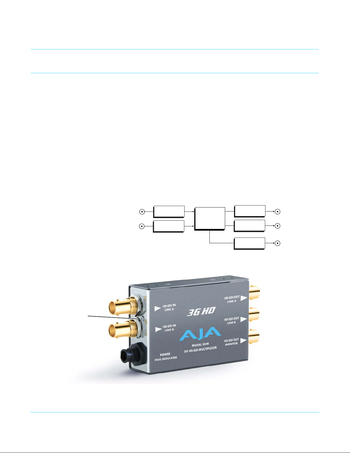
Block Diagram Figure 1. 3GM, Simplified Block Diagram
I/O Connections
3GM v1.5 www.aja.com
NOTE: The Lock LED indicates valid input video by color. Green is SD video, red is HD/Dual Link
video, amber is 3G video, off is no input.
4
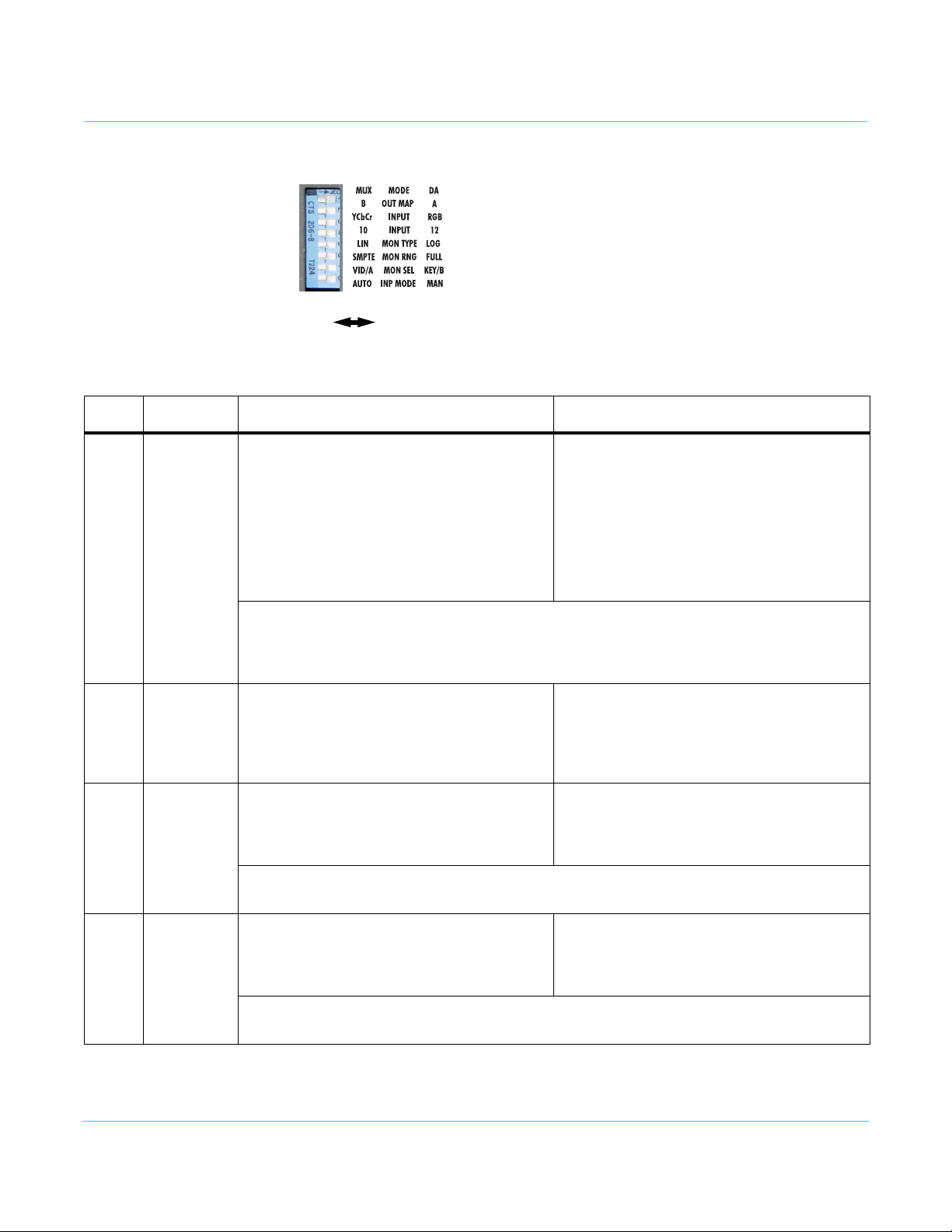
DIP Switches
LEFT RIGHT
OFF ON
User Controls
The user interface for the 3GM is an 8-position DIP switch accessible through a cut-out in
the bottom of the unit.
Table 1. 3GM DIP Switch Settings
Switch FUNCTION LEFT RIGHT
1 MODE:
Multiplex
or DA
2 OUT MAP:
3G A or 3G B
output map
(when set to
output 3G)
3 INPUT:
Input signal
color space:
YCbCr/RGB
MUX:
Converts between Dual-link (SMPTE 372M) and
3G (SMPTE 425M).
A Dual-Link input results in a 3G output (mode
A or B).
A 3G-SDI input (mode A or B) results in a DualLink output
Note: In both cases, the monitor output for a 3G or Dual-Link input will be a downconverted HD
(SMPTE 292M compliant) output.
Note: In both cases, if a single HD or SD SDI signal is fed to the Link A input connector, 3GM
enters DA mode and routes that SDI input signal to all three output connectors.
B:
Selects 3G B output mapping.
3G output is set to the B mapping structure.
YCbrCr:
If Dipswitch 8 is set to Manual or there is no
payload ID, the 3GM will behave as if the input
video is in the YC color space.
Note: In both cases, if payload ID is present and Dipswitch 8 is set to Auto, the 3GM uses the
video specifications in the payload ID.
DA:
Places device in distribution amplifier mode.
A Dual-Link input results in a Dual-Link output
A 3G-SDI input results in a 3G output
(either in mode A or B).
A:
Selects 3G A output mapping.
3G output is set to the A mapping structure.
RGB:
If Dipswitch 8 is set to Manual or there is no
payload ID, the 3GM will behave as if the input
video is in the RGB color space.
4 INPUT:
3GM v1.5 www.aja.com
Input signal
bit depth:
10 or 12-bit
10-Bit:
If Dipswitch 8 is set to Manual or there is no
payload ID, the 3GM will behave as if the input
video is 10-bit.
NOTE: In both cases if payload ID is present and Dipswitch 8 is set to Auto, the 3GM uses the
video specifications in the payload ID.
12-Bit:
If Dipswitch 8 is set to Manual or there is no
payload ID, the 3GM will behave as if the input
video is 12-bit.
5
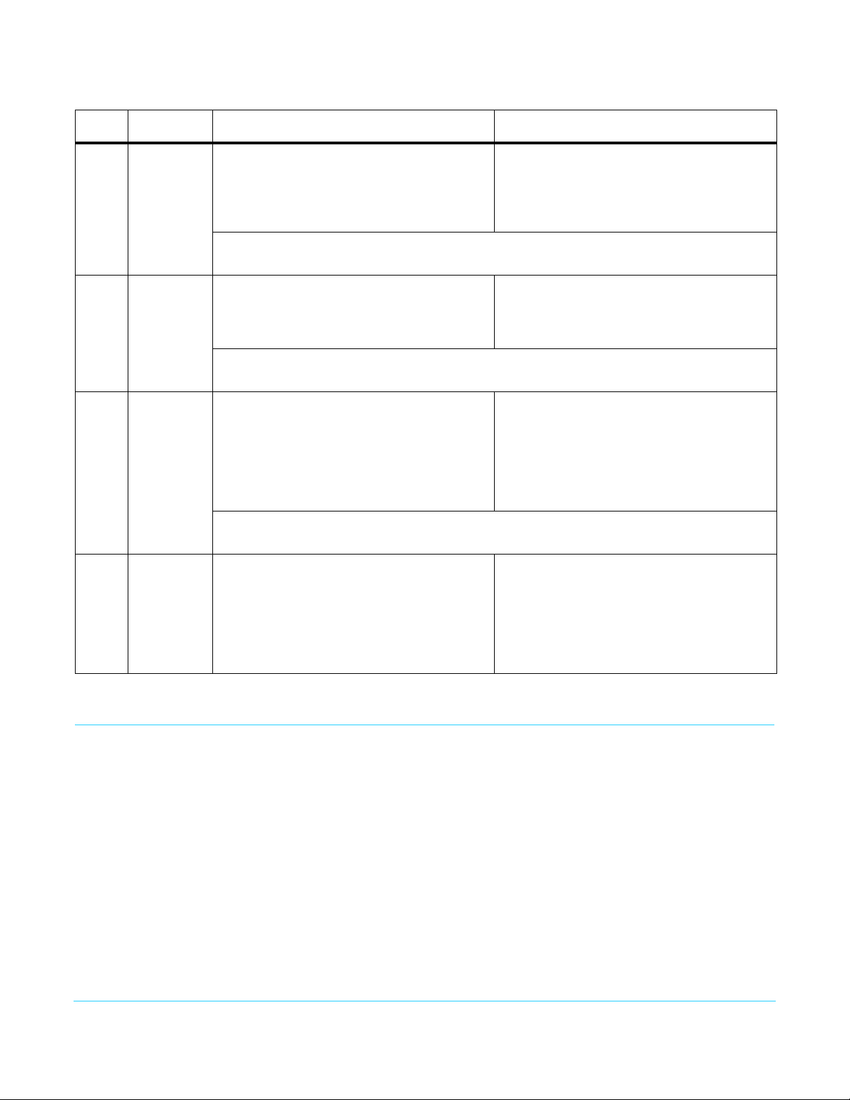
Table 1. 3GM DIP Switch Settings
Switch FUNCTION LEFT RIGHT
5 MON TYPE:
Linear or
log color
6 MON RNG:
SMPTE or
Full range
color values
7 MON SEL:
Video or Key
for Monitor
output
LIN:
Configure input video as linear color.
Will colorspace convert and resample as
needed.
Note: Switches 5, 6, and 7 only affect the monitor output. This switch has no effect on the
primary outputs.
SMPTE:
Defines input video as SMPTE color range
(040h-3ACh).
Note: Switches 5, 6, and 7 only affect the monitor output. This switch has no effect on the
primary outputs.
VID/A:
For video input with an Alpha channel, this
sets the monitor output to Video in the case of
4:4:4:4 video input.
For video input without an Alpha channel, this
sets the monitor output to be Link A.
Note: Switches 5, 6, and 7 only affect the monitor output. This switch has no effect on the
primary outputs.
LOG:
Configure input video as logarithmic color.
Will perform a 10-bit Cineon to 8-bit linear
conversion before colorspace converting and
resampling the monitor output.
FULL:
Defines input video as FULL color range (004h3FBh).
KEY/B:
For video input with an Alpha channel, this sets
monitor output to the Alpha (key) in the case of
4:4:4:4 video input.
For video input without an Alpha channel, this
sets the monitor output to be Link B.
8 INP MODE:
Automatic
or Manual
Setup
Installation
AUTO:
If payload ID is present, the 3GM uses data
from the payload ID information to set color
space and bit depth (switches 3 and 4).
If payload ID is not present, the 3GM reverts to
switches 3 and 4 for input information.
In normal operation the 3GM uses between 4 and 6 watts of power. Because it is
designed to use the outer case and the attached cables for heat dissipation, the case can
feel warm to the touch. This is normal. Although the 3GM has been tested for proper
operation in an ambient temperature up to 45 degrees Celsius (113 F), it is recommended
to not position the 3GM in close proximity to other warm surfaces or airflow.
To install, connect BNC cables to the desired source and destination devices and apply
power to the converter (AJA power supply included).
MAN:
The 3GM uses switches 3 and 4 for color space
and bit depth, regardless of whether payload
ID is present or not.
3GM v1.5 www.aja.com
6
 Loading...