

AJA 3G-AMA Users Manual
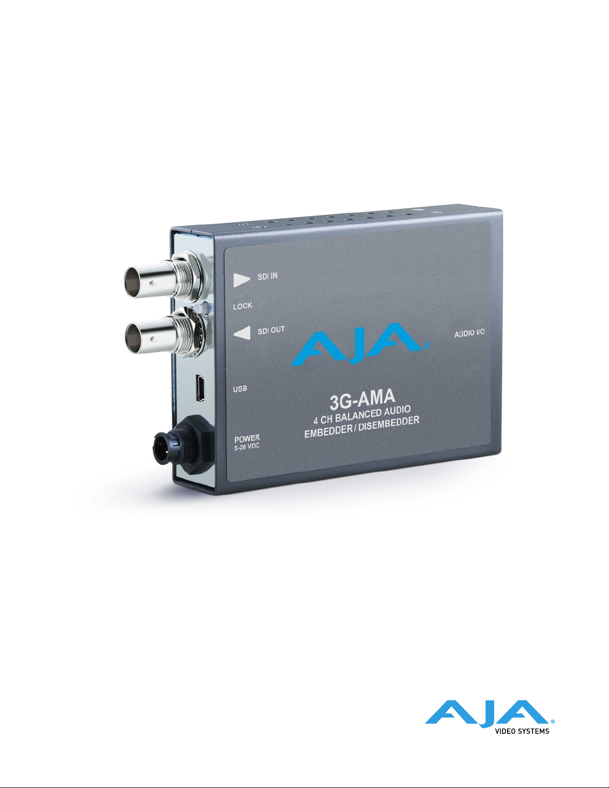
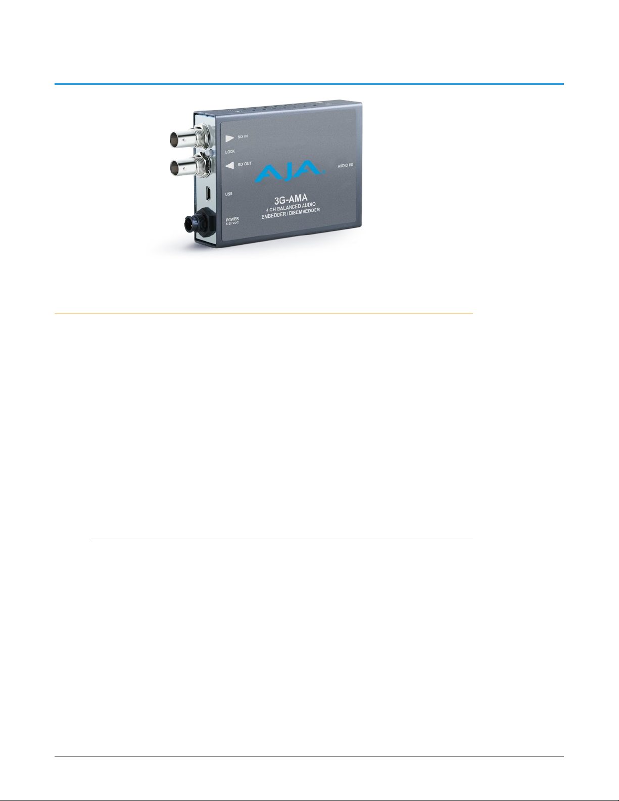
3G-AMA Mini-Converter
4-Ch Balanced Embedder/Disembeder
Installation and Operation Guide
Version 1.1r1
Published May 1, 2018

Notices
Trademarks
Copyright
AJA® and Because it matters.® are registered trademarks of AJA Video Systems, Inc.
for use with most AJA products. AJA™ is a trademark of AJA Video Systems, Inc. for
use with recorder, router, software and camera products. Because it matters.™ is a
trademark of AJA Video Systems, Inc. for use with camera products.
CION®, Corvid Ultra®, lo®, Ki Pro®, KONA®, KUMO®, ROI® and T-Tap® are registered
trademarks of AJA Video Systems, Inc.
AJA Control Room™, KiStor™, Science of the Beautiful™, TruScale™, TruZoom™,
V2Analog™ and V2Digital™ are trademarks of AJA Video Systems, Inc.
All other trademarks are the property of their respective owners.
Copyright © 2018 AJA Video Systems, Inc. All rights reserved. All information in
this manual is subject to change without notice. No part of the document may be
reproduced or transmitted in any form, or by any means, electronic or mechanical,
including photocopying or recording, without the express written permission of AJA
Video Systems, Inc.
Contacting AJA Support
When calling for support, have all information at hand prior to calling. To contact AJA
for sales or support, use any of the following methods:
Telephone +1.530.271.3190
FAX +1.530.271.3140
Web https://www.aja.com
Support Email support@aja.com
Sales Email sales@aja.com
3G-AMA Mini-Converter v1.1r1 2 www.aja.com

Contents
Notices . . . . . . . . . . . . . . . . . . . . . . . . . . . . . . . . . . . . . . 2
Trademarks . . . . . . . . . . . . . . . . . . . . . . . . . . . . . . . . . . . . . . . . . . . 2
Copyright . . . . . . . . . . . . . . . . . . . . . . . . . . . . . . . . . . . . . . . . . . . . 2
Contacting AJA Support . . . . . . . . . . . . . . . . . . . . . . . . . . . . . . . . . . . 2
Chapter 1 – Introduction . . . . . . . . . . . . . . . . . . . . . . . . . . . 4
Overview. . . . . . . . . . . . . . . . . . . . . . . . . . . . . . . . . . . . . . . . . . . . .4
Features. . . . . . . . . . . . . . . . . . . . . . . . . . . . . . . . . . . . . . . . . . . .4
3G-AMA Simplied Block Diagram. . . . . . . . . . . . . . . . . . . . . . . . . . .5
3G-AMA I/O Connections. . . . . . . . . . . . . . . . . . . . . . . . . . . . . . . . . 5
User Controls . . . . . . . . . . . . . . . . . . . . . . . . . . . . . . . . . . . . . . . . . . 5
DIP Switches . . . . . . . . . . . . . . . . . . . . . . . . . . . . . . . . . . . . . . . . . 5
Mini-Cong Control . . . . . . . . . . . . . . . . . . . . . . . . . . . . . . . . . . . . 6
Installation. . . . . . . . . . . . . . . . . . . . . . . . . . . . . . . . . . . . . . . . . . . . 6
Breakout Cable Pinouts. . . . . . . . . . . . . . . . . . . . . . . . . . . . . . . . . . . . 7
Chapter 2 – Operation. . . . . . . . . . . . . . . . . . . . . . . . . . . . .8
Default Operational Settings . . . . . . . . . . . . . . . . . . . . . . . . . . . . . . . . 8
DIP Switches. . . . . . . . . . . . . . . . . . . . . . . . . . . . . . . . . . . . . . . . . . . 8
DIP Switch Settings. . . . . . . . . . . . . . . . . . . . . . . . . . . . . . . . . . . . . 8
Switches 4 and 5 Channel Mapping For Embedded Groups . . . . . . . . . . .9
Switches 6 and 7 Channel Mapping For Disembeded Groups. . . . . . . . . 10
USB Control and Setup—Using AJA Mini-Cong . . . . . . . . . . . . . . . . . . 10
Acquiring Mini-Cong . . . . . . . . . . . . . . . . . . . . . . . . . . . . . . . . . . 10
Installing Mini-Cong . . . . . . . . . . . . . . . . . . . . . . . . . . . . . . . . . . 11
Running Mini-Cong. . . . . . . . . . . . . . . . . . . . . . . . . . . . . . . . . . . 12
Operating Mini-Cong . . . . . . . . . . . . . . . . . . . . . . . . . . . . . . . . . 13
Tabbed Screens . . . . . . . . . . . . . . . . . . . . . . . . . . . . . . . . . . . . . . 14
Audio-1 Tab Screen . . . . . . . . . . . . . . . . . . . . . . . . . . . . . . . . . . . . . 15
Analog Audio Inputs . . . . . . . . . . . . . . . . . . . . . . . . . . . . . . . . . . . 15
Analog Audio Outputs . . . . . . . . . . . . . . . . . . . . . . . . . . . . . . . . . 15
Audio-2 Tab Screen . . . . . . . . . . . . . . . . . . . . . . . . . . . . . . . . . . . . . 16
Packet Processing Control . . . . . . . . . . . . . . . . . . . . . . . . . . . . . . . 16
Analog Audio Levels . . . . . . . . . . . . . . . . . . . . . . . . . . . . . . . . . . . 16
About Audio Levels . . . . . . . . . . . . . . . . . . . . . . . . . . . . . . . . . . . 17
Update Tab Screen. . . . . . . . . . . . . . . . . . . . . . . . . . . . . . . . . . . . . . 17
Info Tab Screen . . . . . . . . . . . . . . . . . . . . . . . . . . . . . . . . . . . . . . . . 18
Appendix A – Specications . . . . . . . . . . . . . . . . . . . . . . . . 19
3G-AMA Tech Specs . . . . . . . . . . . . . . . . . . . . . . . . . . . . . . . . . . . . . 19
Appendix B – Safety and Compliance . . . . . . . . . . . . . . . . . .21
Warranty and Liability Information . . . . . . . . . . . . . . . . . . . .29
Limited Warranty on Hardware. . . . . . . . . . . . . . . . . . . . . . . . . . . . . . 29
Limitation of Liability . . . . . . . . . . . . . . . . . . . . . . . . . . . . . . . . . . . . 30
Governing Law and Language; Your Rights. . . . . . . . . . . . . . . . . . . . . . 30
Index. . . . . . . . . . . . . . . . . . . . . . . . . . . . . . . . . . . . . . .31
3G-AMA Mini-Converter v1.1r1 3 www.aja.com
Chapter 1 – Introduction
Overview
The 3G-AMA is a triple rate 4 channel analog audio embedder/disembedder.
Analog audio can be embedded and disembedded simultaneously. The
embedder is user selectable, on a channel pair basis, to either pass input audio
or embed input audio from the provided breakout cable. The ability to pass
incoming ancillary data makes it possible to embed up to 16channels of audio by
cascading four units. Horizontal ancillary data (HANC) packets in compliance with
SMPTE 291M can also be dropped at the input. Analog audio levels are selectable,
via USB connection and Mini-Config software.
The 3G-AMA automatically detects and configures to the input video standard.
3G-SDI formats up to and including 2048x1080p 60 YCbCr 4:2:2 are supported
(see ""Appendix A Specifications" on page 19 for a complete listing). SDI video
loops through the device with minimal delay. Loop through embedded SDI audio
supports up to 16 channels.
NOTE: 2048x1080p/psf 29.97 and 30 formats support a maximum of 8 channels
embedded audio.
Features
• Triple rate 3G, HD, and SD-SDI Embedder/Disembedder
• 4 Channel Balanced Analog Audio I/O
• Supplied breakout cable for balanced analog audio - XLR connectors.
• 1 x BNC 3G-SDI input
• 1 x BNC 3G-SDI output
• Setup via DIP switch or PC/Mac using USB port and supplied USB cable (MiniCong conguration software application available via download from AJA
website)
• Uses universal input +5V power supply AJA model DWP-U-R1 (included)
3G-AMA Mini-Converter v1.1r1 4 www.aja.com

EQ
Cable Driver
Analog Input
Analog Input
Analog Input
Analog Input
1
2
3
4
3G-AMA Simplified Block Diagram
3G-SDI In
XLR Breakout Cable
1
(Ch 1)
2
(Ch 2)
3
(Ch 3)
4
(Ch 4)
USB Port
(connect to
PC or Mac)
DIP Switch
User Interface
MiniCong
3G-AMA I/O Connections
3G SDI
Input BNC
ADC
ADC
ADC
ADC
Embed and Pass-through
Packet Processor
Control
Dis-
Embedder
DAC
DAC
DAC
DAC
3G-SDI Out 1
XLR Breakout Cable
Analog Output
(Ch 1)
Analog Output
(Ch 2)
Analog Output
(Ch 3)
Analog Output
(Ch 4)
Lock LED
3G SDI
Input BNC
USB Port
DC Power
Input
NOTE: The LOCK LED indicates valid input video by color. Off is no signal, green is SD
User Controls
DIP Switches
The 3G-AMA has an 8 position DIP switch accessible through a cut-out in the
bottom of the unit. The DIP switches are used to configure the unit’s audio
embedding and disembedding, and control ancillary data.
Analog I/O
D-Connector
(attaches to
supplied cable)
4 Input, 4 Output
Break-Out Cable
with XLR Balanced
Connectors
video, red is HD video, amber is 3G video.
3G-AMA Mini-Converter v1.1r1 5 www.aja.com

Figure 1. 3G-AMA DIP Switches and Label
DIP Switch Setting
LEFT RIGHT
1 2 3 4 5 6 7 8
Factory default switch settings are all in the leftmost position.
The exact functions of the DIP switches are described in "DIP Switch Settings" on
page 8
Mini-Config Control
LOCAL
ON
ON
0
0
0
0
ON
CONTROL
REMOTE
EMBD 1/2
EMBD 3/4
EMBD GRP L
EMBD GRP H
DISEMBD GRP L
DISEMBD GRP H
PASS HANC
OFF
OFF
1
1
1
1
OFF
The Mini-Config application can also be used to configure the unit’s audio
embedding and disembedding functions. Configuration set via Mini-Config is
stored in the unit through subsequent power cycles.
Installing and using Mini-Config are described in "USB Control and Setup—Using
AJA Mini-Config" on page 10
Installation
Typically, 3G-AMA installation consists of the following steps:
1. Ensure the converter is disconnected from power.
2. Connect video equipment to the converter BNCs.
3. Connect the breakout audio cable to the converter.
4. Connect audio equipment to the breakout cable.
5. Apply power to the converter (AJA power supply included).
6. The converter will now run using the default factory settings. If you wish to
alter the factory settings you can either:
• Change the DIP switch 2 - 8 settings.
- or -
• Install the AJA Mini-Cong software on your computer,
• attach the converter via USB,
• change the DIP switch 1 setting to LOCAL, and
• make your changes using the Mini-Cong setup screens.
3G-AMA Mini-Converter v1.1r1 6 www.aja.com
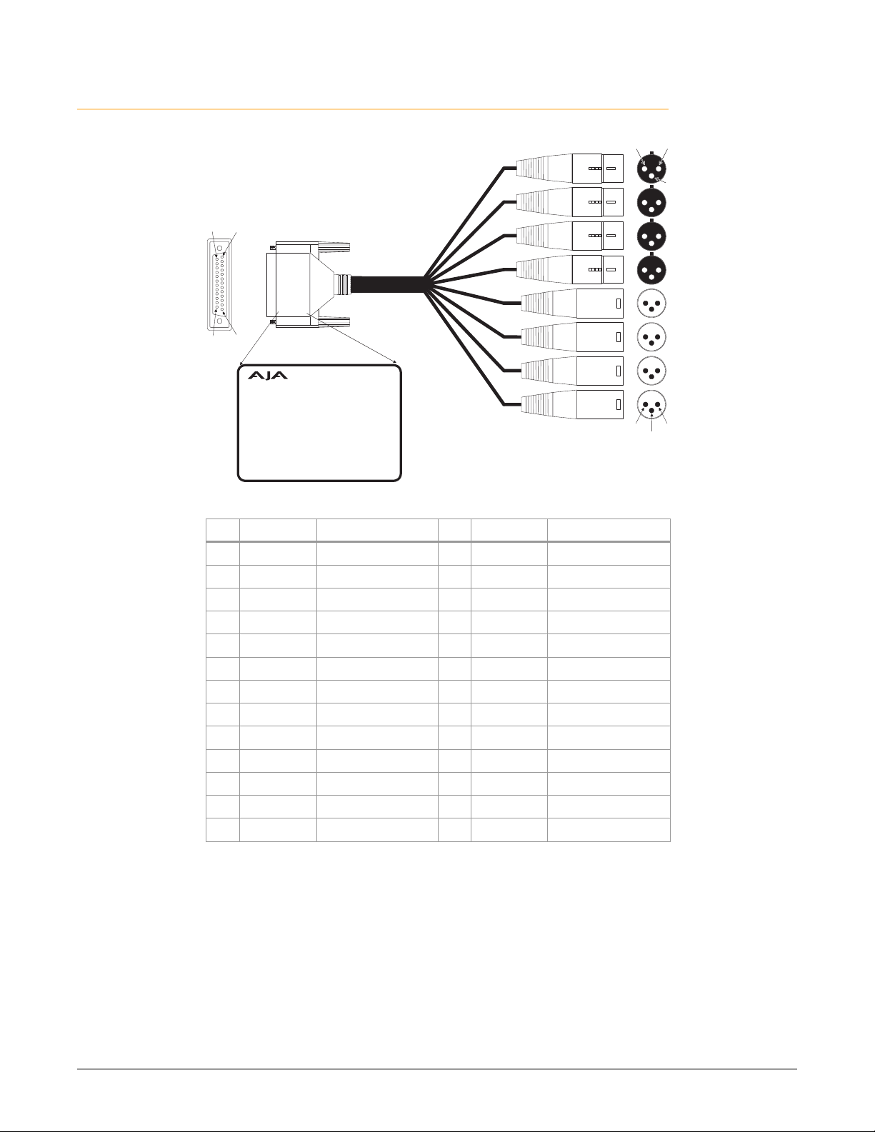
Breakout Cable Pinouts
End Vi
pin
pin
pin 2pin 1
3
Figure 2. AES Breakout Cable Illustration, XLR Connectors
ew Side View
pin 1
14
Input A
pin
Input B
Input C
Input D
Output A
pin 13
25
Channel Index
Input A
Input B
Input C
Input D
Output A
Output B
Output C
Output D
= Analog In Ch. 1
= Analog In Ch. 2
= Analog In Ch. 3
= Analog In Ch. 4
= Analog Out Ch. 1
= Analog Out Ch. 2
= Analog Out Ch. 3
= Analog Our Ch. 4
Output B
Output C
Output D
pin 1 pin 2
Table 1. XLR DB25 Breakout Cable Pinouts
Pin Function Pin, <connector> Pin Function Pin, <connector>
1 In 4 + 2, XLR Input D 14 In 4 - 3, XLR Input D
2 In 4 GND 1, XLR Input D 15 In 3 + 2, XLR Input C
3 In 3 - 3, XLR Input C 16 In 3 GND 1, XLR Input C
4 In 2+ 2, XLR Input B 17 In 2 - 3, XLR Input B
5 In 2 GND 1, XLR Input B 18 In 1 + 2, XLR Input A
6 In 1 - 3, XLR Input A 19 In 1 GND 1, XLR Input A
7 Out 4 + 2, XLR Output D 20 Out 4 - 3, XLR Output D
8 Out 4 GND 1, XLR Output D 21 Out 3 + 2, XLR Output C
9 Out 3 - 3, XLR Output C 22 Out 3 GND 1, XLR Output C
10 Out 2 + 2, XLR Output B 23 Out 2 - 3, XLR Output B
11 Out 2 GND 1, XLR Output B 24 Out 1 + 2, XLR Output A
12 Out 1 - 3, XLR Output A 25 Out 1 GND 1, XLR Output A
13 NC NC
pin 3
3G-AMA Mini-Converter v1.1r1 7 www.aja.com

Chapter 2 – Operation
Default Operational Settings
The 3G-AMA converter ships from the factory with the following configuration:
• Local (DIP switch) control.
• Input analog audio channels 1-4 are embedded to SDI output channels 1-4,
overwriting any existing embedded audio.
• Input SDI embedded audio channels 1-4 are disembedded to analog audio
output channels 1-4.
• All HANC packets pass from SDI input to output, except for embedded output
audio channels 1-4.
• Analog audio levels are set to 0 dBfs = +24 dBu (Pro 1).
If these settings apply to your requirements, you can simply connect the video
and audio input and output signal cables and power up the unit.
For other applications, you can configure the unit using its DIP switch settings, or
by using the Mini-Config application and a PC or Mac via USB. Analog audio levels
can only be set using Mini-Config.
DIP Switches
The 3G-AMA DIP switches configure the audio embedding and disembedding
functions, and control ancillary data.
DIP Switch Settings
DIP switch settings used to configure various functions are described below.
Table 2. 3G-AMA DIP Switch Setting Descriptions
SWITCH FUNCTION DIP Set LEFT (default) DIP Set RIGHT
1 Control Selects Local (DIP), and
blocks Mini-Cong control.
2 Audio Embedding for
Channels 1/2 (EMBD 1/2)
3 Audio Embedding for
Channels 3/4 (EMDB 3/4)
4 Channel Mapping For
Low Embedded Groups
(EMBD GRP L)
5 Channel Mapping For
High Embedded Groups
(EMBD GRP H)
(ON) Overwrite or embed
new channel 1/2 packets.
(ON) Overwrite or embed
new channel 3/4 packets.
Switches 4 and 5 operate together to determine Embedded
channel mapping.
0 represents a Left DIP switch position
1 represents a Right DIP switch position
Refer to "Embedded Output Channel Mapping" on page 9 for
specic settings.
Selects Remote (Mini-Cong),
and disables DIP switches 2-8.
(OFF) If SW 8 is set to ON: Pass
any channel 1/2 packets from
input SDI.
If SW 8 is set to OFF: Delete all
packets from input SDI.
(OFF) If SW 8 is set to ON: Pass
any channel 3/4 packets from
input SDI.
If SW 8 is set to OFF: Delete all
packets from input SDI.
3G-AMA Mini-Converter v1.1r1 8 www.aja.com

6 Channel Mapping For
Low Disembedding
Groups (DISEMBD GRP L)
7 Channel Mapping For
High Disembedding
Groups (DISEMBD GRP H)
8 Pass or Drop HANC input
packets. (PASS HANC)
NOTE: 2048x1080p/psf 29.97 and 30 formats support a maximum of 8 channels of
embedded audio. When one of these formats is present and embedding is turned
on, the PASS HANC DIP switch will be ignored and all incoming packets will be
dropped before embedding any new audio packets.
Switches 6 and 7 operate together to determine Disembedded
channel mapping.
0 represents a Left DIP switch position
1 represents a Right DIP switch position
Refer to "Disembedded Input Channel Mapping" on page 10
for specic settings.
(ON) All incoming HANC
packets are passed unless
the embedder settings
above require all or part of
them to be over-written.
(OFF) All incoming HANC
packets are dropped before
embedding any new audio
packets. Embedder settings
above determine all embedded
audio output.Disembedding is
not aected.
Switches 4 and 5 Channel Mapping For Embedded Groups
The following table shows how combinations of setting these two switches
affects embedded channel mapping.
Table 3. Embedded Output Channel Mapping
DIP SW 4
EMBD GRP L
Left (0) Left (0) 1 —> 1 1
Right (1) Left (0) 1 —> 2 5
Left (0) Right (1) 1 —> 3 9
Right (1) Right (1) 1 —> 4 13
DIP SW 5
EMBD GRP H
Audio Input
Channel
2 —> 2
3 —> 3
4 —> 4
2 —> 6
3 —> 7
4 —> 8
2 —> 10
3 —> 11
4 —> 12
2 —> 14
3 —> 15
4 —> 16
SDI Embedded
Group
SDI Embedded
Output Channel
3G-AMA Mini-Converter v1.1r1 9 www.aja.com

Switches 6 and 7 Channel Mapping For Disembeded Groups
The following table shows how combinations of setting these two switches
affects disembedding channel mapping.
Table 4. Disembedded Input Channel Mapping
DIP SW 6
DISEMBD GRP L
Left (0) Left (0) 1 1 —> 1
Right (1) Left (0) 2 5 —> 1
Left (0) Right (1) 3 9 —> 1
Right (1) Right (1) 4 13 —> 1
DIP SW 7
DISEMBD GRP H
SDI Embedded
Input Group
SDI Embedded
Input Channel
2 —> 2
3 —> 3
4 —> 4
6 —> 2
7 —> 3
8 —> 4
10 —> 2
11 —> 3
12 —> 4
14 —> 2
15 —> 3
16 —> 4
Audio Output
Channel
USB Control and Setup—Using AJA Mini-Config
Your AJA Mini-Converter can be used right out of the box for some applications
since it is designed to recognize inputs and perform standard actions
automatically by default. However, to use its full capability, you must use AJA’s
Mini-Config software application for PCs and Macs. This same application can be
used to update to new Mini-Converter software released by AJA.
NOTE: DIP switch 1 must be ON (Remote, Right) to permit Mini-Config control of the unit.
Acquiring Mini-Config
AJA’s Mini-Config application is available for download from the AJA website.
To download the latest Mini-Config package, which includes the Mini-Config
application, Mini-Converter firmware, and documentation, go to:
https://www.aja.com/products/mini-converters/mini-config-software
Select either the Windows or Mac icon to download the desired version.
Mini-Converter Documentation
Included with the Mini-Config package is a complete set of documentation for
all Mini-Converters supported by Mini-Config. A .PDF of the Installation and
Operation Guide for the currently connected Mini-Converter can be accessed from
the Mini-Config UI via the Help/Manual drop-down menu.
3G-AMA Mini-Converter v1.1r1 10 www.aja.com
 Loading...