

Page 1

COMP ACT DISC STEREO SYSTEM
SISTEMA ESTEREO CON REPRODUCTOR DE DISCOS COMPACTOS
CHAINE STEREO A VEC LECTEUR DE DISQUES COMP ACTS
XH-A1000
OPERA TING INSTRUCTIONS
MANUAL DE INSTRUCCIONES
MODE D’EMPLOI
En (English)
For assistance and information
call toll free 1-800-BUY-AIWA
(United States and Puerto Rico)
E (Español)
F (Français)
8A-MTM-903-11
000223BKY-Y-M
U
Page 2

XH-A1000
CORRECTION
Please read the incorrect description in the
Operating Instructions as follows.
Page 21
AI EDIT RECORDING
WRONG
6
Press q REC/REC MUTE to start
recording.
RIGHT
6
Press qREC/REC MUTE and then press
c /d within 2 seconds to start
recording.
Page 22
PROGRAMMED EDIT
RECORDING
WRONG
8
Press q REC/REC MUTE to start
recording.
RIGHT
8
Press qREC/REC MUTE and then press
c /d within 2 seconds to start
recording.
CORRECCION
Interprete, porfavor, las descripciones
incorrectas del manual de la forma sigulente.
Página 21
GRABACIÓN DE EDICIÓN AI
ERRONEO
6
Presione qREC/REC MUTE para iniciar
la grabación.
ORRECTO
6
Presione q REC/REC MUTE y luego
pulse c /d antes de que pasen 2
segundos para iniciar la grabación.
Página 22
GRABACIÓN DE EDICIÓN
PROGRAMADA
ERRONEO
8
Presione qREC/REC MUTE para iniciar
la grabación.
ORRECTO
8
Presione q REC/REC MUTE y luego
pulse c /d antes de que pasen 2
segundos para iniciar la grabación.
CORRECTION
Prière d’apporter les corrections suivantes au
mode d’emploi.
Page 21
ENREGISTREMENT PAR
MONTAGE INTELLIGENT
MAUVAIS
6
Appuyez sur qREC/REC MUTE pour
lancer l’enregistrement.
BON
6
Appuyez sur qREC/REC MUTE puis
appuyer sur c/d dans les 2 secondes
qui suivent pour lancer l’enregistrement.
Page 22
ENREGISTREMENT PAR
MONTAGE PROGRAMME
MAUVAIS
8
Appuyez sur qREC/REC MUTE pour
lancer l’enregistrement.
BON
8
Appuyez sur qREC/REC MUTE puis
appuyer sur c/d dans les 2 secondes
qui suivent pour lancer l’enregistrement.
8A-MTM-919-01
0001A-Y
Printed in Japan
Page 3

ENGLISH
WARNING
TO REDUCE THE RISK OF FIRE OR ELECTRIC
SHOCK, DO NOT EXPOSE THIS APPLIANCE TO
RAIN OR MOISTURE.
CAUTION
RISK OF ELECTRIC SHOCK
DO NOT OPEN
“CAUTION:TO REDUCE THE RISK OF
ELECTRIC SHOCK,
DO NOT REMOVE COVER (OR BACK).
NO USER-SERVICEABLE PARTS INSIDE.
REFER SERVICING TO QUALIFIED
SERVICE PERSONNEL.”
Explanation of Graphical Symbols:
The lightning flash with arrowhead symbol,
within an equilateral triangle, is intended to alert
the user to the presence of uninsulated
“dangerous voltage” within the product’s
enclosure that may be of sufficient magnitude
to constitute a risk of electric shock to persons.
3 Mounting surface — Place the unit on a flat, even surface.
4 Ventilation — The unit should be situated with adequate
space around it so that proper heat ventilation is assured.
Allow 10 cm (4 in.) clearance from the rear and the top of the
unit, and 5 cm (2 in.) from each side.
- Do not place the unit on a bed, rug, or similar surface that
may block the ventilation openings.
- Do not install the unit in a bookcase, cabinet, or airtight rack
where ventilation may be impeded.
5 Objects and liquid entry — Take care that objects or liquid
do not get inside the unit through the ventilation openings.
6 Carts and stands — When placed or
mounted on a stand or cart, the unit should
be moved with care.
Quick stops, excessive force, and uneven
surfaces may cause the unit or cart to overturn
or fall.
7 Condensation — Moisture may form on the CD pickup lens
when:
- The unit is moved from a cold spot to a warm spot
- The heating system has just been turned on
- The unit is used in a very humid room
- The unit is cooled by an air conditioner
When this unit has condensation inside, it may not function
normally. Should this occur, leave the unit for a few hours,
then try to operate again.
8 Wall or ceiling mounting — The unit should not be mounted
on a wall or ceiling, unless specified in the Operating
Instructions.
The exclamation point within an equilateral
triangle is intended to alert the user to the
presence of important operating and
maintenance (servicing) instructions in the
literature accompanying the appliance.
Owner’s record
For your convenience, record the model number and serial
number (you will find them on the rear of your unit) in the space
provided below . Please ref er to them when you contact y our Aiwa
dealer in case of difficulty.
Model No. Serial No. (Lot No.)
CX-A1000
SX-WA1000
SX-C1800
SX-R1800
PRECAUTIONS
Read the Operating Instructions carefully and completely before
operating the unit. Be sure to keep the Operating Instructions
for future reference. All warnings and cautions in the Operating
Instructions and on the unit should be strictly followed, as well
as the safety suggestions below.
Installation
1 Water and moisture — Do not use this unit near w ater , such
as near a bathtub, washbowl, swimming pool, or the like.
2 Heat — Do not use this unit near sources of heat, including
heating vents, stov es, or other appliances that generate heat.
It also should not be placed in temperatures less than 5°C
(41°F) or greater than 35°C (95°F).
Electric Power
1 Power sources — Connect this unit only to power sources
specified in the Operating Instructions, and as marked on the
unit.
2 Polarization — As a safety f eature, some units are equipped
with polarized AC power plugs which can only be inserted
one way into a power outlet. If it is difficult or impossible to
insert the AC power plug into an outlet, turn the plug over and
try again. If it is not still inserted easily into the outlet, please
call a qualified service technician to service or replace the
outlet. To avoid defeating the safety feature of the polarized
plug, do not force it into a power outlet.
3 AC power cord
- When disconnecting the AC power cord, pull it out by the
AC power plug. Do not pull the cord itself.
- Never handle the AC power plug with wet hands, as this
could result in fire or shock.
- Power cords should be firmly secured to av oid being severely
bent, pinched, or walked upon. Pay particular attention to
the cord from the unit to the power socket.
- Avoid overloading AC outlets and extension cords beyond
their capacity, as this could result in fire or shock.
4 Extension cord — To help prevent electric shock, do not use
a polarized AC power plug with an e xtension cord, receptacle,
or other outlet unless the polarized plug can be completely
inserted to prevent exposure of the blades of the plug.
5 When not in use — Unplug the AC power cord from the power
outlet if the unit will not be used for several months or more.
When the cord is plugged in, a small amount of current
continues to flow to the unit, even when the power is turned
off.
2
ENGLISH
Page 4

Outdoor Antenna
1 Power lines — When connecting an outdoor antenna, make
sure it is located away from power lines.
2 Outdoor antenna grounding — Be sure the antenna system
is properly grounded to provide protection against unexpected
voltage surges or static electricity build-up. Article 810 of the
National Electrical Code, ANSI/NFP A 70, provides inf ormation
on proper grounding of the mast, supporting structure, and
the lead-in wire to the antenna discharge unit, as well as the
size of the grounding unit, connection to grounding terminals,
and requirements for grounding terminals themselves.
Antenna Grounding According to the National Electrical Code
ANTENNA LEAD IN WIRE
GROUND CLAMP
ELECTRIC
SERVICE
EQUIPMENT
NEC-NATIONAL ELECTRICAL CODE
ANTENNA DISCHARGE
UNIT
(NEC SECTION 810-20)
GROUNDING
CONDUCTORS
(NEC SECTION 810-21)
GROUND CLAMPS
POWER SERVICE GROUNDING
ELECTRODE SYSTEM
(NEC ART 250 PART H)
Maintenance
Clean the unit only as recommended in the Operating
Instructions.
Damage Requiring Service
Have the units serviced by a qualified service technician if:
- The AC power cord or plug has been damaged
- Foreign objects or liquid have got inside the unit
- The unit has been exposed to rain or water
- The unit does not seem to operate normally
- The unit exhibits a marked change in performance
- The unit has been dropped, or the cabinet has been damaged
DO NOT ATTEMPT TO SERVICE THE UNIT YOURSELF.
TABLE OF CONTENTS
PREPARATIONS
CHECK YOUR SYSTEM AND ACCESSORIES .................4
BASIC CONNECTIONS ......................................................4
CONNECTING OTHER EQUIPMENTS ..............................6
CONNECTING A DVD PLAYER .........................................8
REMOTE CONTROL...........................................................9
BEFORE OPERATION........................................................9
SOUND
AUDIO ADJUSTMENTS .................................................. 11
GRAPHIC EQUALIZER.................................................... 12
DSP SURROUND............................................................. 13
RADIO RECEPTION
MANUAL TUNING ............................................................ 14
PRESETTING STATIONS ................................................ 15
TAPE PLAYBACK
BASIC OPERATIONS ...................................................... 16
CD PLAYING
BASIC OPERATIONS ...................................................... 17
PROGRAMMED PLAY..................................................... 19
RECORDING
BASIC RECORDING........................................................ 20
AI EDIT RECORDING ...................................................... 2 1
PROGRAMMED EDIT RECORDING............................... 22
DOLBY SURROUND
ADJUSTING SPEAKER LEVEL...................................... 23
PLAY WITH DOLBY PRO LOGIC.................................... 24
LISTENING T O DOLBY DIGITAL SURROUND SOUND ...... 25
KARAOKE
MICROPHONE MIXING ................................................... 26
CD KARAOKE PROGRAM.............................................. 28
SOUND
En
CLOCK AND TIMER
SETTING THE CLOCK..................................................... 29
SETTING THE SLEEP TIMER ......................................... 29
SETTING THE TIMER ...................................................... 30
GENERAL
CARE AND MAINTENANCE ........................................... 31
SPECIFICATIONS ............................................................ 32
TROUBLESHOOTING GUIDE......................................... 33
PARTS INDEX ...................................................
Back cover
ENGLISH
3
Page 5

PREPARATIONS
CHECK YOUR SYSTEM AND
ACCESSORIES
XH-A1000
CX-A1000 Compact disc stereo cassette receiver
SX-WA1000 Front speakers
SX-C1800 Center speaker
SX-R1800 Surround speakers
Remote control AM antenna FM antenna
Operating Instructions, etc.
BASIC CONNECTIONS
The DOLBY PRO LOGIC system which is the biggest feature of
this stereo system provides you with multichannel sound in your
home. Enjoy the enriched home theater system by connecting
the TV set or video equipments with this unit.
Complete setting and connection of the main unit, supplied
speakers, your TV and video equipments according to the
following procedure.
Before connecting the AC cord
The rated voltage of your unit shown on the rear panel is 120 V
AC. Check that the rated voltage matches your local voltage.
IMPORTANT
Connect the speakers, antennas, and all optional equipment first.
Then connect the AC cord.
There are no difference between the front speakers as well as
the surround speakers. Both speakers of its kind can be
connected as L (left) or R (right).
1
Connect the right speaker to the main unit.
1 Connect the speaker cord with the white stripe to the
SPEAKERS LOW FREQ R 0 terminal and the black cord
to the 9 terminal.
SPEAKER
Ω
P : 6
Wind the tip of the cord around the terminal. Then tighten
the terminal. Check that the cord is connected securely.
IM
4
ENGLISH
Page 6

2 Connect the blue colored speaker cord to SPEAKERS
HIGH FREQ R jack.
To position the antennas
FM antenna:
Extend the antenna horizontally in a T-shape and fix its ends to
a wall.
AM antenna:
Position and rotate this antenna to find the best reception.
SOUND
S
R
E
K
A
E
P
S
HIGH FREQ
2
Connect the left speaker to the main unit.
S
R
E
K
A
E
P
S
HIGH FREQ
Connect the blue colored speaker cord to SPEAKERS HIGH
FREQ L terminal, and another speaker cord to the
SPEAKERS LOW FREQ L terminals in the same manner as
step 1.
3
Connect the surround speakers to the main unit.
Connect the right surround speaker cord to SURROUND
SPEAKERS R terminal, and the left to SURROUND
SPEAKERS L terminal.
4
Connect the center speaker.
Connect the center speaker cord to CENTER SPEAKER
terminal.
To stand the AM antenna on a surface
Fix the claw to the slot.
POSITIONING THE SPEAKERS
T o achie ve the optim um effects obtainab le with the DOLBY PRO
LOGIC system, it is important to position the speakers properly .
Refer to the following illustration to find out the best location in
your room.
12 1
3
PREPARATIONS
En
5
Connect the supplied antennas.
Connect the FM antenna to FM 75 Ω terminals and the AM
antenna to AM LOOP terminals.
FM antenna
AM antenna
6
Connect other equipments.
Some audio and video equipments (LD player, MD player,
DVD player, TV, etc.) can be connected to this unit.
See page 6 for details.
7
Connect the AC cord to an AC outlet.
The DEMO (Demonstration) will begin when the AC cord is
plugged into an AC outlet for the first time after purchase . To
deactivate the DEMO, set the clock.
3
1 Front speakers
2 Center speaker
Position in the center of the two front speakers. In addition,
position on or below the TV set, if connecting a TV set to the
unit.
3 Surround speakers
Place the surround speakers directly to the side of or slightly
behind the listening area. Align them horizontally, about 1
meter above ear height.
NOTE
• No sound is heard from the center and surround speakers when
the DOLBY PRO LOGIC, the DSP SURROUND system and
the 5.1CH (page 25) are set to off.
• The sound is heard from the center speaker when the DOLBY
PRO LOGIC or the 5.1CH (page 25) is set to on.
ENGLISH
5
Page 7

To mount the surround speakers on a wall
Use wall mounting screws (not supplied).
Select a spot that will hold the weight of the speakers and
carefully mount the surround speakers so that they are firmly
secured.
Aiwa disclaims any
responsibility for injury to
persons or other accidents
caused by not fitting the
surround speakers properly
or if the place of the
installation is not suitable.
NOTE
• Be sure to connect the speaker
cords correctly. Contact of bare
conductor with other jacks or
other conductors may cause short
R
E
K
circuits in SPEAKERS terminals
or malfunctions.
A
E
P
S
Ω
6
:
P
M
I
• Do not leave objects generating magnetism, such as credit
cards, near the speakers, as the objects may be damaged.
• Do not bring the FM antenna near metal objects or curtain rails.
• Do not bring the AM antenna near other optional equipment,
the stereo system itself, the AC cord or speaker cords, since
noise will be picked up.
• Do not unwind the AM antenna wire.
CONNECTING AN OUTDOOR ANTENNA
For better FM reception, use of an outdoor antenna is
recommended.
Connect the outdoor antenna to FM 75 Ω terminals.
VIDEO2/LD/TV jacks
A video equipment, an LD player or a cable TV, etc. can be
connected to these jacks.
• Use the audio cable and video cable commercially available.
• To input signals from the connected equipment to this unit,
connect the cables to VIDEO2/LD/TV IN jacks.
To output signals from this unit to the connected equipment,
connect the cables to VIDEO2/LD/TV OUT jacks.
• Connect L (left) output of the connected equipment and AUDIO
L of this unit, R (right) output and AUDIO R by the audio cable .
VIDEO3 jacks
A video equipment, a camcorder or a TV game, etc. can be
connected to these jacks. T urn VOLUME to "0" before connecting
equipment to VIDEO 3 jacks.
• Use the audio cable and video cable commercially available.
• Connect L (left) output of the connected equipment and AUDIO IN
L of this unit, R (right) output and AUDIO IN R by the audio cable
.
• Connect Video output of the connected equipment and VIDEO
IN of this unit by the video cable.
REC OUT/AUDIO MONITOR jacks
A recording equipment such as an MD recorder, a CD-R/RW recorder
or a cassette deck, or the TV set etc. can be connected to these jacks.
The sounds from the equipment connected to VIDEO1/DVD/MD
or VIDEO2/LD/TV can be recorded or monitored as well.
• Use the audio cable commercially available.
• Connect L (left) output of the connected equipment and AUDIO
L of this unit, R (right) output and AUDIO R by the audio cable .
MONITOR/VIDEO OUT jacks
The TV set, etc. can be connected to these jacks.
The videos from the equipment connected to VIDEO1/DVD/MD
or VIDEO2/LD/TV can be monitored.
• Use the video cable commercially available.
CD DIGITAL OUT (OPTICAL) jack
A digital equipment such as an MD recorder, a D A T dec k, a digital
cassette deck or a digital amplifier, etc. can be connected to this
jack. The digital signals from the CD pla yer of this unit are output
to the connected equipment.
• Use the optical cable commercially available.
• Before connecting an optical cable remove the dust cap a
from CD DIGITAL OUT (OPTICAL) jack.
CONNECTING OTHER
EQUIPMENTS
A video equipment, the TV set, an LD pla yer , a DVD player or an
MD player, etc. can be connected to this unit.
VIDEO1/DVD/MD jacks
A video equipment, a DVD player, or an MD player, etc. can be
connected to these jacks.
• Use the audio cable and video cable commercially available.
• To input signals from the connected equipment to this unit,
connect the cables to VIDEO1/DVD/MD IN jacks.
To output signals from this unit to the connected equipment,
connect the cables to VIDEO1/DVD/MD OUT jacks.
• Connect L (left) output of the connected equipment and AUDIO
L of this unit, R (right) output and AUDIO R by the audio cab le.
6
ENGLISH
• When CD DIGITAL OUT (OPTICAL) jack is not used, attach
the dust cup a.
PHONO IN jacks
A turntable can be connected to these jacks. Use an Aiwa
turntable equipped with a built-in equalizer amplifier.
AUX IN jacks
A playback equipment such as the TV set or an MD player, etc.
can be connected to these jacks.
• Use the audio cable and video cable commercially available.
• Connect L (left) output of the connected equipment and AUDIO
L of this unit, R (right) output and AUDIO R by the audio cable .
NOTE
The signals input through VIDEO 1 IN jack are output from VIDEO
2 OUT or MONITOR OUT. The signals input through VIDEO 2 IN
jack are output from VIDEO 1 OUT or MONITOR OUT.
Page 8

Connection example
Video deck, LD player,
Cable TV, etc.
to Audio out
jacks and
Video out jack
o
o
VIDEO2/LD/TV
VIDEO2/LD/TV
to Audio in jacks and
Video in jack
o
o
REC OUT/
VIDEO1/DVD/MD
VIDEO1/DVD
AUDIO
MONITOR
MONITOR/
VIDEO OUT
o
o
to Audio in jacks
o
to Digital in jack
o
CD DIGITAL OUT
(OPTICAL)
DVD deck, Video deck, MD
player, etc.
to Audio out jacks and
Video out jack
o
o
CD-ROM driver,
MD recorder, etc.
CX-A1000 (rear)
SOUND
PREPARATIONS
to Audio in jacks and
Video in jack
Turntable
o
PHONO IN
AUX IN
En
TV
CX-A1000 (front)
o
to Video in jack
o
to Audio out jacks
Camcorder
to Audio out jacks
and Video out jack
ENGLISH
7
Page 9

SELECTING EXTERNAL AUDIO/VIDEO
SOURCES
AUX/PHONO/5.1CH
CONNECTING A DVD PLAYER
5.1CH INPUT jacks of this unit support the DOLBY DIGITAL
SURROUND system (see page 25).
Connect a DVD player with 5.1ch output jacks to this unit using
cables with RCA phono plugs as follows:
VIDEO 1/2/3
f,g
To play equipment connected to the unit, proceed as follows.
1
Press VIDEO1/2/3 or AUX/PHONO/5.1CH
repeatedly to select a desired source.
The source names are displayed cyclically as below.
When VIDEO1/2/3 is pressed
VIDEO1 VIDEO2 VIDEO3
When AUX/PHONO/5.1CH is pressed
AUX 5.1chIN
Select one of the sources depending on the equipment
connected to the input terminals on the unit.
∗
While the headphones are plugged in, 5.1chIN is not displayed.
2
Play the connected equipment.
∗
PHONO
This unit’s jack DVD player’s jack
5.1CH INPUT FRONT (L, R) 5.1CH OUTPUT FRONT (L, R), etc.
5.1CH INPUT SURROUND (L, R) 5.1CH OUTPUT SURROUND (L, R), etc.
5.1CH INPUT CENTER 5.1CH OUTPUT CENTER, etc.
5.1CH INPUT SUB WOOFER 5.1CH OUTPUT SUB WOOFER, etc.
VIDEO/AUX IN (L, R) LINE OUT (L, R), etc.
NOTE
(See NOTE .)
To monitor a video source
The selected video source is indicated on the display and the
video signal through MONITOR/VIDEO OUT jack is output on
the TV.
To adjust the sound level of equipments connected to
the input jacks (except a equipment connected to PHONO
jacks)
When the sound level of the external source is much higher or
much lower than that of other function sources, adjust it as f ollows.
1 Press VIDEO1/2/3 or AUX/PHONO/5.1CH repeatedly so that
the name of the jacks connected with the concerned
equipment is displayed.
Example: To adjust the sound level of equipment connectedto
VIDEO 1, press VIDEO1/2/3 repeatedly to display VIDEO1.
2 Play the equipment.
3 Press f or g until the sound level becomes the same
as that of other function sources.
NOTE
• During recording, the sound level can not be adjusted.
• The sound level of the connected turntable cannot be adjusted.
NOTE
• If the DVD player is not connected to AUX IN jacks:
- the spectrum analyzer does not show the sound level of the
DVD player.
- the sound from the connected D VD player cannot be recorded.
To remove these limitations, connect LINE OUT jacks of the
DVD player to AUX IN jacks of this unit besides connecting to
5.1CH INPUT jacks.
The signals through AUX IN jacks enab le the spectrum analyzer
to work and the recording to be done.
Refer also to the operating instructions of the DVD player.
• The DOLBY DIGITAL SURROUND sound cannot be recorded
in any way.
8
ENGLISH
Page 10

REMOTE CONTROL
BEFORE OPERATION
Inserting batteries
Detach the battery cover on the rear of the remote control and
insert two R6 (size AA) batteries.
When to replace the batteries
The maximum operational distance between the remote control
and the sensor on the main unit should be approximately 5 meters
(16 feet). When this distance decreases, replace the batteries
with new ones.
Using the remote control
The instructions in this manual refer mainly to the buttons on the
main unit. Buttons on the remote control with the same names
as those on the main unit can be used as well.
c/d PRESET on the remote control
The function is the same as that of d on the main unit.
NOTE
• If the remote control is not going to be used for an extended
period of time, remove the batteries to prevent possible
electrolyte leakage.
• The remote control may not operate correctly when:
- The line of sight between the remote control and the remote
sensor inside the display window is exposed to intense light,
such as direct sunlight
- Other remote controls are used nearby (those of a television,
etc.)
Function
FL DISPLAY
POWER
To turn the power on
Press one of the function buttons (TAPE, TUNER/BAND, VIDEO1/
2/3, AUX/PHONO/5.1CH or CD).
Playback of the inserted disc or tape begins, or the previously
tuned station is received (Direct Play Function).
POWER is also available.
To turn the power off
Press POWER.
Illumination guide
Whenever POWER or one of the function buttons is pressed,
the buttons for the selected operation light up or flash.
Example:
guide to setting the current time.
Demo mode
When the AC cord is plugged into an AC outlet for the first time
after purchase, the Demo mode will begin in the display window .
When the power is turned on, the Demo mode will end. When
the power is turned off, the Demo mode will begin again.
Until the clock is set, the Demo mode will begin whenever the
power is turned off.
When the clock is set, the Demo mode will not begin even if the
power is turned off. (See “SETTING THE CLOCK” on page 29
to set the clock.)
When CLOCK is pressed, f and g light as a
buttons
SOUND
PREPARATIONS
En
To activate the Demo mode
Press DEMO while the power is turned on or off. The Demo mode
will begin in the display window.
When one of the button is pressed or the control is turned, the
Demo mode will end.
SETTING DISPLAY MODE
By pressing FL DISPLAY as following, the illumination color,
brightness level of the displa y and the spectrum analyzer display
can be changed.
To change the illumination color
The lighting color around the function buttons and above the CD
compartment can be changed.
1 Press FL DISPLAY
2 Within 4 seconds, turn MULTI JOG to select the illumination
color. The modes are displayed cyclically as below.
The color will be automatically set after 4 seconds.
BLUE UMBER PURPLE
once so that the current mode is displayed.
ENGLISH
9
Page 11

To change the brightness level of the display
1 Press FL DISPLAY twice so that the current mode is
displayed.
2 Within 4 seconds, turn MULTI JOG to select the dimmer mode.
The modes are displayed cyclically as below.
The mode will be automatically set after 4 seconds. 3.
DIM-OFF: The normal display.
DIMMER 1: The illumination of the display is dimmer than
usual.
DIMMER 2: The illumination of the display is dimmer than
DIMMER 1.
DIMMER 3: The illumination of the display is dimmer than
DIMMER 2. The spectrum analyzer and the
button lamps light off.
To change the spectrum analyzer display
1 Press FL DISPLAY three times so that the current mode is
displayed.
2 Within 4 seconds, turn MULTI JOG to select the spectrum
analyzer display. The modes are displa yed cyclically as below.
The mode will be automatically set after 4 seconds.
NORMAL REVERSE PEAK
1
Press ECO.
The current power-economizing mode status (ECO OFF/ECO
ON/ECO AUTO) will be displayed.
2
Turn MULTI JOG within 4 seconds to change the
power-economizing mode.
3
Within 4 seconds, press ENTER to set the
selected power-economizing mode.
Standby power consumption
If the power-economizing mode is OFF: 55 W
If the power-economizing mode is ON or AUTO: 1.9 W
NOTE
T o view the cloc k when all the display lights turn off, press CLOCK
so that the time is displayed for 4 seconds.
SETTING POWER ECONOMIZING MODE
MULTI JOG
ENTER
ECO
CLOCK
Setting this unit to power economizing mode reduces power
consumption as follows.
ECO ON
• When the power is turned off, all the display lights turn off, and
only the indicator on POWER lights; however, when the clock
is not set, the window turns to the demo display.
• When the power turns on due to timer recording (page 30), the
display brightness lev el is set to “DIMMER 3”, all button lamps
are off, and the volume is set to the minimum level (0).
• The display brightens only when operating the unit. When the
unit has not been used for 10 seconds, the brightness level
switches to the dimmer mode previously selected.
(If the display brightness level is set to “DIM-OFF”, the
brightness does not change. When the level is “DIMMER 3”,
the button lamps are also turned off.)
ECO AUTO
• In addition to the conditions of ECO ON, if CD or tape does not
play for 10 minutes or if there is no audio input from any
connected external equipment for 10 minutes when VIDEO1,
2, 3, AUX or PHONO is selected as the source , the power shuts
off. Exceptionally, the power does not shut off when the 5.1CH
is selected.
ECO OFF
The economizing mode does not work.
4-CHANNEL MULTI-AMPLIFIER SYSTEM
T o provide reinf orcement for the ultra-lo w frequencies, in addition
to the Left/Right 2-channel amplifier used to reproduce mud-tohigh-range frequencies, this system incorporates a second L/R
2-channel amplifier just for reproduction of ultra-low frequencies
–making it, in effect, a 4-amplifier system. By utilizing discrete
amplifiers for mid to-high-frequencies and low frequencies, highquality sonic reproduction that is virtually free from distortion
can be realized.
This Multi Amplifier System, which utilizes independent circuitry
for the different frequency ranges, enables superb sonic
reproduction free from distortion.
BUILT-IN SUBWOOFER SYSTEM
The built-in subwoofer system has a separate subwoofer cavity
area that is part of the loudspeaker cabinet structure, which acts
as a sonic filter to cut distortion components. (In the Multi
Amplifier System, the ultra-low frequency signals transmitted from
their own independent amplifier are reproduced in this area.)
This separate construction gives a clear, rich definition to bass
reproduction and it can realize clear, well-defined mid-to-high
frequency signals.
And AIWA's built-in subwoof er system incorporates a subwoofer
capable of powerful, satisfying bass perf ormance with true stereo
separation.
10
ENGLISH
Page 12

SOUND
g
AUDIO ADJUSTMENTS
T-BASS
BBE
PHONES
VOLUME
VOLUME CONTROL
Turn VOLUME on the main unit, or press VOL N
or M on the remote control.
The volume level is displayed as a number from 0 to MAX (50).
The volume level is automatically set to 20 when the power is
turned off with the volume level set to 21 or more.
To change the left/right balance
Press MANUAL SELECT on the remote control. L/R is displayed
for 2 seconds. Press
these 2 seconds.
• The DOLBY PRO LOGIC (page 24) and the DOLBY DIGITAL
SURROUND (page 25) front speakers level is also changed.
ff
f or
ff
gg
g on the remote control within
gg
MANUAL
SELECT
T-BASS
VOL /
f,
BBE SYSTEM
The BBE system enhances the clarity of high-frequency sound.
It also enriches the Karaoke function to make your voice sound
clear and pleasant.
Press BBE.
Each time it is pressed, the level changes. Select one of the
three levels or the off position to suit your preference.
NOTE
When playing back a tape recorded with BBE, it is recommended
that BBE be set to off to avoid distorted high frequency sound.
SUPER T -BASS SYSTEM
The T-BASS system enhances the realism of low-frequency
sound.
Press T -BASS.
Each time it is pressed, the level changes. Select one of the
three levels or the off position to suit your preference.
SOUND
PREPARATIONS
SOUND
En
Using the headphones
Connect headphones to PHONES jack with a stereo standard
plug (ø6.3 mm,
No sound is output from the speakers while the headphones are
plugged in.
• When the headphones are plugged in, the DSP SURROUND
system (page 13), the DOLBY PRO LOGIC (page 24) and the
5.1CH (page 25) do not function.
1
/4 inch).
NOTE
Low-frequency sound may be distorted when the T-BASS system
is used for a disc or tape in which low-frequency sound is already
emphasized. In this case, cancel the T-BASS system.
ENGLISH
11
Page 13

GRAPHIC EQUALIZER
SELECTING THE PROGRAMMED
EQUALIZATION CURVE
This unit provides the following 5 different equalization curves.
ROCK: Powerful sound emphasizing treble and bass
POP: More presence in the vocals and midrange
LATIN: Accented higher frequencies for latin-type music
CLASSIC: Enriched sound with heavy bass and fine treble
JAZZ: Accented lower frequencies for jazz-type music.
GEQ
MUL TI
JOG
GEQ
f,g
SETTING A NEW EQUALIZATION CURVE
MANUALLY
GEQ FREQ
(HIGH)
GEQ FREQ
(LOW)
MULTI
JOG
The equalization curve can be customized to suit your preference.
1
Press GEQ FREQ (LOW).
The lowest level frequency indicator flashes for 8 seconds.
2
Within 8 seconds, turn MULTI JOG to adjust the
level of the lowest frequency.
1
Press GEQ.
The current mode is displayed.
2 Within 4 seconds, turn MULTI JOG or press f
or g to select a desired mode. The modes are
displayed cyclically as below.
ROCK
GEQ M5 GEQ M1
The mode will be automatically set after 4 seconds.
To cancel the selected mode
Press GEQ twice so that “GEQ OFF” is displayed.
To select with the remote control
Press GEQ repeatedly until the desired program mode is
displayed. Each mode and “GEQ OFF (cancel)” appear cyclically .
POP
LATIN
Program mode
Manual mode
CLASSIC
GEQ M2GEQ M3GEQ M4
JAZZ
3
Press GEQ FREQ (HIGH).
The highest level frequency indicator flashes for 8 seconds.
4
Within 8 seconds, turn MULTI JOG to adjust the
level of the highest frequency.
The frequency level indicators between the lowest and the
highest are adjusted accordingly.
12
ENGLISH
Page 14

MEMORIZING THE NEW EQUALIZATION
SURROUND
f,g
MANUAL
SELECT
SURROUND
CURVES
DSP SURROUND
GEQ FREQ
MULTI JOG
ENTER
Up to 5 customized equalization curves can be stored on the
manual mode M1-M5.
1
Set a new equalization curve with GEQ FREQ and
MULTI JOG.
See “SETTING A NEW EQUALIZATION CURVE MANUALLY”
on page 12.
The created equalization curve is displayed for 8 seconds.
2
Within 8 seconds, press ENTER.
“GEQ M1” is displayed and all the manual mode indicators
flash for 8 seconds. Go to step 3 within those 8 seconds.
• If this step is not completed within 8 seconds, press GEQ
FREQ first to display “GEQ HIGH” or “GEQ LOW”. Then
press ENTER within 8 seconds.
3
While the manual mode indicators are flashing,
turn MULTI JOG to select a number among from
M1 to M5 and press ENTER.
The equalization curve is stored.
The DSP (Digital Signal Processor) SURROUND system can
create the effect of sound reflected from walls and ceilings. This
system enhances 5 types of sound presence.
DISCO: Sound presence of a disco
LIVE: Sound presence of a live music performance
STADIUM: Sound presence of a stadium
HALL: Sound presence of a concert hall
MOVIE: Sound presence of a movie theater
1
Press SURROUND.
The current mode is displayed.
2 Within 4 seconds, turn MULTI JOG or press f
or g to select a desired mode.
SOUND
En
To select the stored equalization curve
1 Press GEQ.
2 Within 4 seconds, turn MULTI JOG to select a desired number
among from M1 to M5.
Equalization curves are selected automatically to match the DSP
SURROUND modes and can also be selected or turned off to
suit your preference.
When the music source is monaural
Select LIVE, STADIUM or MOVIE to obtain a simulated stereo
effect. When DISCO or HALL is selected, no sound will be heard
from the surround speakers.
To cancel the selected mode
Press SURROUND twice so that “DSP OFF” is displayed. The
selected equalization curve remains.
To adjust the volume of the surround speakers
Press MANUAL SELECT twice or three times on the remote
control. “S-L” or “S-R” is displayed for 2 seconds. Press f or
g on the remote control within these 2 seconds.
• The DOLBY PRO LOGIC (page 23) and the DOLBY DIGITAL
SURROUND (page 25) surround speakers level is also
changed.
NOTE
The DSP SURROUND mode is canceled when:
- the ECHO is turned on.
- the DOLBY PRO LOGIC is turned on.
- the headphones are plugged in.
- the 5.1CH (page 25) is selected.
ENGLISH
13
Page 15

RADIO RECEPTION
MANUAL TUNING
TUNER/
BAND
TUNER
PRESET
MULTI
JOG
POWER
f,g
1
Press TUNER/BAND repeatedly to select the FM
or AM band.
When TUNER/BAND is pressed while the power is off, the
power is turned on directly (Direct Play Function).
2
Press TUNER PRESET repeatedly to select the
manual tuning mode.
Each time the button is pressed, the following three tuning
modes are selected cyclically.
1 Preset tuning mode: The preset number flashes.
2 Auto search mode: “SEARCH” is displayed.
3 Manual tuning mode: “SEARCH” is not displayed and
the preset number does not flash.
SEARCH
Frequency
MONO
TUNER
TUNER/
BAND
Preset
number
To search for a station quickly (Auto Search)
Press TUNER PRESET repeatedly to display “SEARCH” (auto
search mode), and turn MULTI JOG clockwise or
counterclockwise until the frequency starts to change rapidly.
After tuning in to a station, the search stops.
SEARCH
To stop the Auto Search manually, turn MULTI JOG a little in
either direction.
• The Auto Search may not stop at stations with very weak
signals.
• fDOWN and gUP are also available to search for a
station. Keep fDOWN or gUP pressed until the tuner
starts searching. Press the button to stop the search manually.
When an FM stereo broadcast contains noise
Press MONO TUNER on the remote control so that “MONO”
appears on the display.
Noise is reduced, although reception is monaural.
MONO
NOTE
The preset tuning mode is skipped if no station is preset.
3
Turn MULTI JOG clockwise or counterclockwise
to tune in to a station.
The frequency changes as you turn MULTI JOG.
When a station is received, “TUNE” is displayed for 2 seconds.
During FM stereo reception, 1 is displayed.
1
• fDOWN and gUP are also available to tune in to a
station.
To restore stereo reception, press MONO TUNER so that
“MONO” disappears and “STEREO” is displayed for 2 seconds.
To change the AM tuning interval
The default setting of the AM tuning interval is 10 kHz/step. If
you use this unit in an area where the frequency allocation system
is 9 kHz/step, change the tuning interval.
Press POWER while pressing TUNER/BAND on the unit.
To reset the interval, repeat this procedure.
14
ENGLISH
Page 16

PRESETTING STATIONS
PRESET NUMBER TUNING
Use the remote control to select the preset number directly.
TUNER/
BAND
TUNER/
BAND
a
f,g
The unit can store a total of 32 preset stations for all bands.
When a station is stored, a preset number is assigned to the
station. Use the preset number to tune in to a preset station
directly.
1
Press TUNER/B AND to select a band, and tune in
f,g
a
to a station with fDOWN or gUP.
2
Press aSET to store the station.
A preset number beginning from 1 in consecutive order for
each band is assigned to a preset station.
Frequency
TUNER/
BAND
TUNER
PRESET
MULTI
JOG
a
s
d
1
Press TUNER/BAND to select a band.
2
Press numbered buttons 0-9 and +10 to select a
TUNER/
BAND
0-9,+10
c/d
s
a
preset number .
Example:
To select preset number 20, press +10, +10 and 0.
To select preset number 15, press +10 and 5.
Selecting a preset number on the main unit
Press TUNER/BAND to select a band.
Press TUNER PRESET repeatedly until the preset number
flashes (preset tuning mode), and turn MULTI JOG. The preset
numbers are selected in sequence as you turn MULTI JOG.
• dPRESET is also available to select the preset number.
Each time the button is pressed, the next highest number is
selected.
RADIO RECEPTION
En
3
Repeat steps 1 and 2.
No more stations will be stored if a total of 32 preset stations
have already been stored.
NOTE
• When the AM tuning interval is changed, all preset stations are
cleared. The preset stations have to be set again.
•“FULL” is displayed if you attempt to store more than 32 preset
stations.
To clear a preset station
Select the preset number of the station to be cleared with the
numbered buttons. Then, press sCLEAR, and press aSET
within 4 seconds.
The preset numbers of all other stations in the band with higher
numbers are decreased by one.
ENGLISH
15
Page 17
TAPE PLAYBACK
BASIC OPERATIONS
T o stop pla y, press s.
To pause play, press a. To resume play, press again.
To fast forward or rewind, press f or g. Then press s
to stop the tape.
REV MODE
DOLBY NR
zTAPE
OPEN/
CLOSE
Cassette
tray
TAPE
a
s
f,g
jl
1 Press DOLBY NR to turn Dolby NR on or off to
match the playback tape.
hNR
For tapes recorded with DOLBY NR, turn on hNR.
For tapes recorded without DOLBY NR, turn off hNR.
2 Press TAPE and press zTAPE OPEN/CLOSE to
open the cassette tray.
zTAPE OPEN/CLOSE
Cassette tape
Types of tape
Use T ype I (normal), Type II (high/CrO2) or T ype IV (metal) tapes
for playback.
To select a reverse mode
Each time REV MODE is pressed, the reverse mode changes.
[
]
To play one side only, select p.
To play from the side facing upward to the opposite side once
only, select .
To play both sides repeatedly, select ].
[
P
T o start play when the power is off (Direct Play Function)
When a tape is loaded, press TAPE. The power is turned on
and playback begins.
When zTAPE OPEN/CLOSE is pressed, the power is also
turned on.
To set the tape counter to “0000”
Press sCLEAR in stop mode.
The counter is also set to “0000” when the cassette tray is
opened.
Load a tape with the exposed side facing the unit, and the
side to be played back facing upward.
3 Press zT APE OPEN/CLOSE to close the cassette
tray.
4 Press d to start play.
To play the opposite side of the tape, press d again.
Playback
side indicator
x: The side facing upward is being played (forward).
c: The opposite side is being played (reverse).
The tape counter indicates the tape
running length.
MUSIC SENSOR
If there is a 4-second or longer blank between each track, a
search for the beginning of the current or next track during
playback can be done easily.
When the x indicator of d is flashing, press f to move
to the next track or g to mov e to the beginning of the current
track.
When the c indicator of d is flashing, press g to move
to the next track, or f to mov e to the beginning of the current
track.
The search function may not be able to detect trac ks under the
following conditions:
• Blanks of less than 4 seconds between tracks
• Noisy blanks
• Long passages of low-end sound
• Low overall recording levels
16
ENGLISH
Page 18

CD PLAYING
BASIC OPERATIONS
LOADING DISCS
CD
DISC
CHANGE
Press CD, then press zCD OPEN/CLOSE to open
the disc compartment. Load disc(s) with the label
side up.
To load one or two discs, place the discs tray 1 and tray 2.
zCD OPEN
/CLOSE
PLAYING DISCS
dDIRECTION/
PRESET
MUL TI
JOG
DISC
DIRECT PLA Y
Load discs.
To play all discs in the disc compartment (continuous
play), press d.
Play begins with the disc on tray 1.
The indicator of DISC DIRECT PLA Y flashes to indicate the disc
being played.
Number of track
being played
Elapsed playing time
CD EDIT/
CHECK
0-9,+10
CD
zCD
OPEN/
CLOSE
c/d
f,g
s
DISC
DIRECT
PLA Y
CD PLAYING TAPE PLAYBACK
To load three discs, press DISC CHANGE to rotate the trays
after placing two discs. Place the third disc on tray 3.
After placing the discs, press zCD OPEN/CLOSE to close
the disc compartment.
The display shows the information of the disc to be played.
Total number of tracks
Total playing time
Tray number of the disc to be played
To play one disc only (single disc pla y), press one of
DISC DIRECT PLAY 1-3.
The disc with the selected tray number is played once.
Only the indicator of the selected DISC DIRECT PLAY flashes.
Number of track
being played
To play with the remote control
Press DISC DIRECT PLAY, then press one of the numbered
buttons 1-3 within 3 seconds to select a disc.
T o stop play, press s.
To pause play, press a. To resume play, press again.
To search for a particular point during playback, keep f
or g pressed and release the button at the desired point.
To skip to the beginning of a track during playback, turn
MULTI JOG or press f or g repeatedly.
To remove discs, press zCD OPEN/CLOSE.
You can only remove the two discs that face you. When the
disc(s) to be removed does(do) not face you, press DISC
CHANGE repeatedly.
Elapsed playing time
Selected
disc tray
number
En
ENGLISH
17
Page 19

To start pla y when the power is off (Direct Play Function)
RANDOM/REPEAT
Press CD. The power turns on and play of the loaded disc(s)
begins.
When z CD OPEN/CLOSE is pressed, the po wer is also turned
on and the disc compartment is opened.
To check the remaining time
Press CD EDIT/CHECK on the remote control during play. The
amount of time remaining until all tracks finish playing is
displayed. To restore the playing time display, press CD EDIT/
CHECK.
Selecting a track with the remote control
1 Press DISC DIRECT PLAY, then press one of the numbered
buttons 1-3 within 3 seconds to select a disc.
2 Press the numbered buttons 0-9 and +10 to select a track.
Example:
To select the 25th track, press +10, +10 and 5.
To select the 10th track, press +10 and 0.
The selected track starts to play and play continues to the
end of that disc.
Replacing discs during play
While one disc is playing, the other discs can be replaced without
interrupting play.
1 Press DISC CHANGE.
2 Remove the discs and replace with other discs.
3 Press zCD OPEN/CLOSE to close the disc compartment.
NOTE
• When loading an 8-cm (3-inch) disc, make sure to place it onto
the inner circle of the tray precisely.
• Do not place more than one compact disc on one disc tray.
• Do not tilt the unit with discs loaded. Doing so may cause
malfunctions.
• Do not use irregular shape CDs (
octagonal ones). It may result in malfunctions.
• The unit may not play a CD-R/RW disc that is recorded on
personal computers or some kinds of CD-R/RW recorders
because of differences in recording platforms.
• Do not attach any seal or label to either side (the recordable
side or the labeled side) of a CD-R/RW disc. It may cause
malfunction.
example:
heart-shaped,
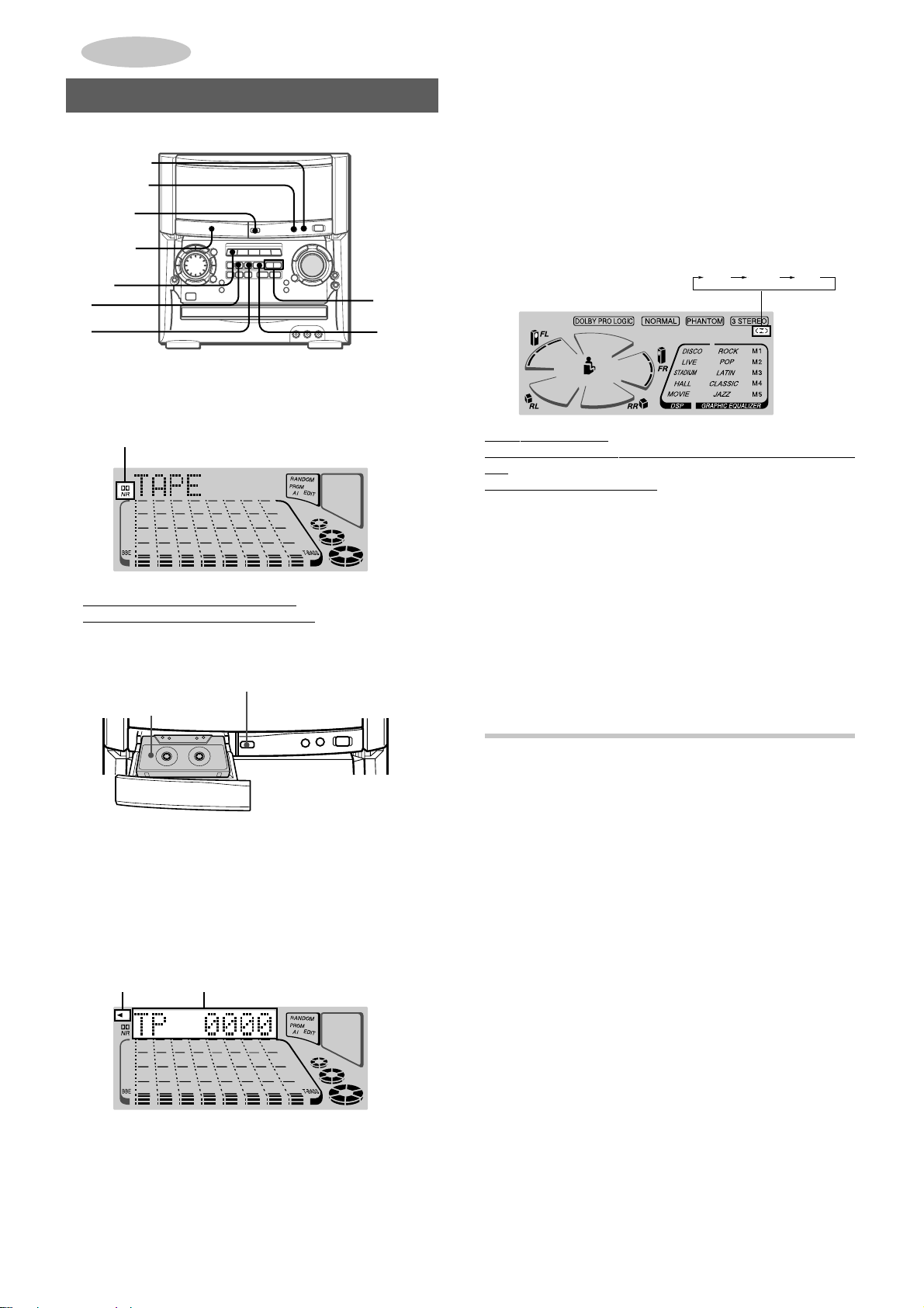
RANDOM/REPEAT PLAY
Use the remote control.
RANDOM PLAY
All the tracks on the selected disc or all the discs can be play ed
randomly.
REPEAT PLAY
A single disc or all the discs can be played repeatedly.
Press RANDOM/REPEAT.
Each time it is pressed, the function can be selected cyclically.
RANDOM play — The line around RANDOM lights up on the
display.
REPEAT play — " lights up on the display.
RANDOM/REPEAT play — The line around RANDOM and
light up on the display.
"
Cancel — The line around RANDOM and " disappear from
the display.
To play all discs, press d to start play.
To play a single disc, press DISC DIRECT PLAY, then press
one of the numbered buttons 1-3 within 3 seconds to start play.
NOTE
• During random play, it is not possible to skip to the previously
played track with f or MULTI JOG.
• Random play is canceled when the numbered button is pressed
to select a track.
18
ENGLISH
Page 20

PROGRAMMED PLAY
To check the program
Each time f or g is pressed in stop mode, a disc number,
track number, and program number will be displayed.
Up to 30 tracks can be programmed from any of the inserted
discs.
PRGM
0-9,+10
DISC
DIRECT
PLAY
Use the remote control.
1
Press PRGM twice in stop mode.
“– –” and the line of PRGM appear on the display.
RANDOM/REPEAT
c/d
f,g
s
PRGM
To clear the program
Press sCLEAR in stop mode.
CD PLAYING
To add tracks to the program
Repeat steps 2 and 3 in stop mode. The trac k will be programmed
after the last programmed track.
To change the programmed tracks
Clear the program and repeat all the steps again.
To play the programmed tracks repeatedly
After programming the tracks, press RANDOM/REPEAT once
so that " appears on the display.
NOTE
• During programmed play , y ou can not use random pla y or check
the remaining time.
• During programmed play, you can not select a track. “Can’t
USE” is displayed if you attempt to select a track.
•“FULL” is displayed if you attempt to program more than 30
tracks.
BLANK SKIP PLAY
The silent portions between tracks recorded on a CD can be
skipped during playback.
• When PRGM is pressed once in step 1, the unit enters the
CD KARAOKE PROGRAM (page 28).
2
Press DISC DIRECT PLAY, then press one of the
numbered buttons 1-3 within 3 seconds to select
a disc.
Go to the next step when the tray stops rotating.
3
Press the numbered buttons 0-9 and +10 to
program a track.
Example:
To select the 25th track, press +10, +10 and 5.
To select the 10th track, press +10 and 0.
Total playing
Selected track
number
4
Repeat steps 2 and 3 to program other tracks.
5
Press d to start play.
Program number
Total number of
selected tracks
time of the
selected tracks
1
Press CD BLANK SKIP on the main unit.
“CD BLANK SKIP ON” is displayed and a b lank skip mark will
appear in the display.
2
Press d to start playback.
The silent portions between tracks will be skipped, and the
sound will be played back without interruption. If a track fades
out (ends with the sound gradually decreasing), the fadeout
portion will also be skipped.
To return to normal playback
Press CD BLANK SKIP again. “CD BLANK SKIP OFF” is
displayed and the blank skip mark in the display will disappear.
NOTE
• There may be a case where BLANK SKIP PLAY does not
function correctly.
• BLANK SKIP PLA Y is automatically canceled when perf orming
AI EDIT RECORDING (page 21), PROGRAMMED EDIT
RECORDING (page 22), or recording during PROGRAMMED
PLAY (left column) or RANDOM PLAY (page 18).
Blank skip mark
En
ENGLISH
19
Page 21

RECORDING
BASIC RECORDING
This section explains how to record from the tuner , CD play er , or
external equipment.
zTAPE
OPEN/
CLOSE
DOLBY NR
REV MODE
To stop recording, press s.
To pause recording, press a. (Applicable when the recording
source is TUNER, VIDEO1/2/3 or an external equipment
connected to AUDIO IN jacks on the rear or the front.)
To resume recording, press again.
To start recording with the remote control
First press qREC/REC MUTE, and then press d within 2
seconds.
NOTE
“Can’t REC” is displayed if you attempt to record on a tape with
the plastic tabs brocken off.
w
a
s
Preparation
• Set the tape to the point where recording will start.
• Use Type I (normal) and T ype II (high/CrO
1
Load a tape to be recorded.
Load the tape with the exposed side facing the unit, and the
side to be recorded facing upward.
zTAPE OPEN/CLOSE
Cassette tape
To open or close the cassette tray, press zTAPE OPEN/
CLOSE of the cassette tray.
2
Press REV MODE to select the reverse mode.
To record on one side only, select p.
To record on both sides, select or ].
2) tapes for recording.
[
Function
buttons
SOUND ADJUSTMENT DURING
RECORDING
The output volume and tone (except BBE, MIC, ECHO and the
rhythm play function) of the speakers or headphones are freely
varied without affecting the recording.
INSERTING BLANK SPACES
Insertion of 4-second blank spaces enables you to activate the
Music Sensor function. (Applicable when the source is TUNER,
VIDEO1/2/3 or AUX/PHONO/5.1CH.)
1 Press wREC/REC MUTE during recording or while in
recording pause mode.
“REC” on the display flashes for 4 seconds and a 4-second
blank space is made. Then, the deck enters the recording
pause mode.
2 Press a to resume recording.
T o insert a blank space of less than 4 seconds, press wREC/
REC MUTE again while “REC” is flashing.
To insert blank spaces of more than 4 seconds, after the
deck enters recording pause mode, press wREC/REC MUTE
again. Each time the button is pressed, a 4-second blank space
is added.
3
Press DOLBY NR to turn Dolby NR on or off.
To record with DOLBY NR, turn on hNR.
To record without DOLBY NR, turn off hNR.
4
Press one of the function buttons and prepare
the source to be recorded.
To record from a CD, press CD and load the disc(s).
To recor d from a radio broadcast , press TUNER/BAND and
tune in to a station.
To record from the connected source, press VIDEO1/2/3
or AUX/PHONO/5.1CH and play.
5
Press
When the selected function is CD, playback and recording
start simultaneously.
20
ww
wREC/REC MUTE to start recording.
ww
REC
ENGLISH
To erase a recording
Make sure the microphone is not connected to the unit.
Set the microphone volume and the echo level to OFF (page
26).
1 Press TAPE and load the tape to be erased.
2 Set the tape to the point where the erasure is to be started.
3 Set the reverse mode by pressing REV MODE.
4 Press wREC/REC MUTE to start the erasure.
Page 22

AI EDIT RECORDING
CD EDIT/
CHECK
0-9,+10
DISC
DIRECT
PLAY
q
The AI edit recording function enables CD recording without
worrying about tape length and track length. When a CD is
inserted, the unit automatically calculates the total track lengths.
If necessary, the order of trac ks is rearranged so that no tr ack is
cut short.
(AI: Artificial Intelligence)
NOTE
The AI edit recording will not start from a point halfway into the
tape. The tape must be recorded from the beginning of either
side.
Use the remote control from steps 3 to 6.
1
Load the tape into the cassette tray, and press
DOLBY NR to turn Dolby NR on or off.
Load the tape with the side to be recorded on first facing
upward.
2
Press CD and load the disc(s).
3
Press CD EDIT/CHECK once.
The lines of AI EDIT and “AI” light up on the display.
AI
CD
c/d
f,g
s
AI EDIT
6
Press qREC/REC MUTE, and then press
c/d within 2 seconds to start recording.
The tape is rewound to the beginning of the side facing
upward, the lead segment is played through for 10 seconds,
and recording starts. When recording on the side facing
upward (side A) ends, recording on the other side (side B)
starts.
To stop recording
Press s. Recording and CD play stop simultaneously.
To clear the edit program
Press s twice so that the line of EDIT disappears from the
display.
To check the order of the edit program
Before recording, press CD EDIT/CHECK to select side A or B,
and press f or g repeatedly.
Tape side
To add tracks from other discs to the edit program
If there is any time remaining on the tape after step 5, you can
add tracks from other discs in the CD compartment.
1 Press CD EDIT/CHECK to select side A or B.
2 Press DISC DIRECT PLAY, then press one of the numbered
buttons 1-3 within 3 seconds to select a disc.
3 Press the numbered buttons 0-9 and +10 to select tracks.
A track whose playing time is longer than the remaining time
cannot be programmed.
4 Repeat steps 2 and 3 to add more tracks.
5 Start recording.
The line of AI lights off and the line of PRGM lights up.
Time on cassette tapes and editing time
The actual cassette recording time is usually a little longer than
the specified recording time printed on the label. This unit can
program tracks to use the extra time. When the total recording
time is a little longer than the tape’s specified recording time
after editing, the display shows the extra time (without a minus
mark), instead of the time remaining on the tape (with the minus
mark).
Track
number
Program
number
Programmed
track numbers
RECORDING
En
When “PRGM” is selected, press CD EDIT/CHECK again.
4
Press DISC DIRECT PLAY, then press one of the
numbered buttons 1-3 within 3 seconds to select
a disc.
5
Press the numbered buttons 0-9 to designate the
tape length.
10 to 99 minutes can be specified.
Example
In a few seconds, the tracks to be recorded on each side of
the tape are determined.
• f, g and MULTI JOG are also available to designate
: When using a 60-minute tape, press 6 and 0.
the tape length.
Tape length
Tape side A
(facing upward)
Remaining time of side A
Selected tracks for side A
NOTE
• Recording is inhibited if the erasure prevention tab on either
side of the tape is broken off.
• The AI edit function cannot be used with discs containing 31
tracks or more. “TR OVER” is displayed if this is attempted.
ENGLISH
21
Page 23

PROGRAMMED EDIT RECORDING
CD EDIT/
CHECK
0-9,+10
DISC
DIRECT
PLA Y
q
CD
c/d
f,g
5
Press DISC DIRECT PLAY, then press one of the
numbered buttons 1-3 within 3 seconds to select
a disc. Then, press the numbered buttons 0-9 and
+10 to program a track.
Example
DIRECT PLAY and 2, then +10 and 0.
Selected track number
: To select the 10th track of disc 2, press DISC
Remaining time on side A
s
In the programmed edit recording function, the tracks can be
programmed while checking the remaining time on each side of
the tape as the tracks are programmed.
NOTE
The programmed edit recording will not start from a point halfway
in the tape. The tape must be recorded on from the beginning of
either side.
Use the remote control from steps 3 to 8.
1
Load the tape into the cassette tray, and press
DOLBY NR to turn Dolby NR on or off.
Load the tape with the side to be recorded on first facing
upward.
2
Press CD and load the disc(s).
3
Press CD EDIT/CHECK twice.
The lines of PRGM EDIT and “PRGM” light up on the displa y.
PRGM
PRGM EDIT
Program number
6
Repeat step 5 for the rest of the tracks f or side A.
A track whose playing time is longer than the remaining time
cannot be programmed.
7
Press CD EDIT/CHECK to select side B and
Selected disc
number
Programmed track numbers
program the tracks for side B.
After confirming B on the display, repeat step 5.
Tape side B(reverse side)
8
Press qREC/REC MUTE, and then press
c/d within 2 seconds to start recording.
The tape is rewound to the beginning of the side facing
upward, the lead segment is played through for 10 seconds,
and recording starts. When recording on the side A facing
upward ends, recording on the other side B starts.
To stop recording
Press s. Recording and CD play stop simultaneously.
When “AI” is selected, press CD EDIT/CHECK again.
4
Press the numbered buttons 0-9 to designate the
tape length.
10 to 99 minutes can be specified.
Tape length
• f, g and MULTI JOG are also available to designate
the tape length.
Tape side A
Maximum recording
time for side A
To check the order of the programmed track numbers
Before recording, press CD EDIT/CHECK to select side A or B,
and press f or g repeatedly.
Track number
Program number
To change the program of each side
Press CD EDIT/CHECK to select side A or B, and press
sCLEAR to clear the program on the selected side. Then
program tracks again.
To clear the edit program
Press sCLEAR twice so that the line of EDIT disappears from
the display.
Programmed track numbers
Disc number
22
ENGLISH
Page 24
DOLBY SURROUND
NOTE
• Recording is inhibited if the erasure prevention tab on either
side of the tape is broken off.
• Up to 30 tracks can be programmed from any of the inserted
discs.
•“FULL” is displayed if you attempt to program more than 30
tracks.
About cassette tapes
• T o prevent accidental erasure, break off the plastic tabs
on the cassette tape after recording with a screwdriver or
other pointed tool.
Side A
Type II tape
detection
slot
Tab for side A
The DOLBY PRO LOGIC feature and the center and surround
speakers (standard) assure full-scale home theater sound. When
playing back laser discs or video software that have been
recorded in Dolby Surround, astonishingly realistic sound
surrounds the listener to create a new level of audio/visual
entertainment.
Independent control of the five sound channels allows the listener
to enjoy the same type of sound reproduction experienced in
movie theaters. Voices are reproduced in the front and center
sound field, while ambient sounds like cars and crowds are
reproduced on all sides of the listener for an incredibly lifelike
audio/video experience. Please read the following carefully to
“tune” the system’s output to match the characteristics of your
listening space.
Check the following:
• Before using the DOLBY PRO LOGIC, adjust the proper
balance of speaker sound levels.
• Make sure the supplied speakers are properly connected and
positioned (see page 5).
• Make sure the TV set and video unit are properly connected
(see page 7).
• Make sure the laser disc, video tape, etc., support
H.
ADJUSTING SPEAKER LEVEL
RECORDING
DOLBY SURROUND
To record on the tape again, cover the tab openings with
adhesive tape, etc. (On T ype II tapes , take care not to cover
the Type II tape detection slot.)
• 120-minute or longer tapes are extremely thin and easily
deformed or damaged. They are not recommended.
• T ake up an y slac k in the tape with a pencil or similar tool
before use. Slack tape ma y break or jam in the mechanism.
DOLBY NR system
The Dolby Noise Reduction system reduces tape hiss noise.
For optimum performance when playing back a tape
recorded with the DOLBY NR system, turn on the DOLBY
NR system.
MANUAL
DOLBY
PRO
LOGIC
SELECT
h
PRO LOGIC
f,g
f,g
The unit is equipped with a built-in test signal generator called a
noise sequencer for easy balance adjustment of all 5 channels.
The sequencer outputs a noise signal that “travels” from channel
to channel, enabling the simple adjustment of sound level to
achieve, at the listening position, the same apparent loudness
from each channel.
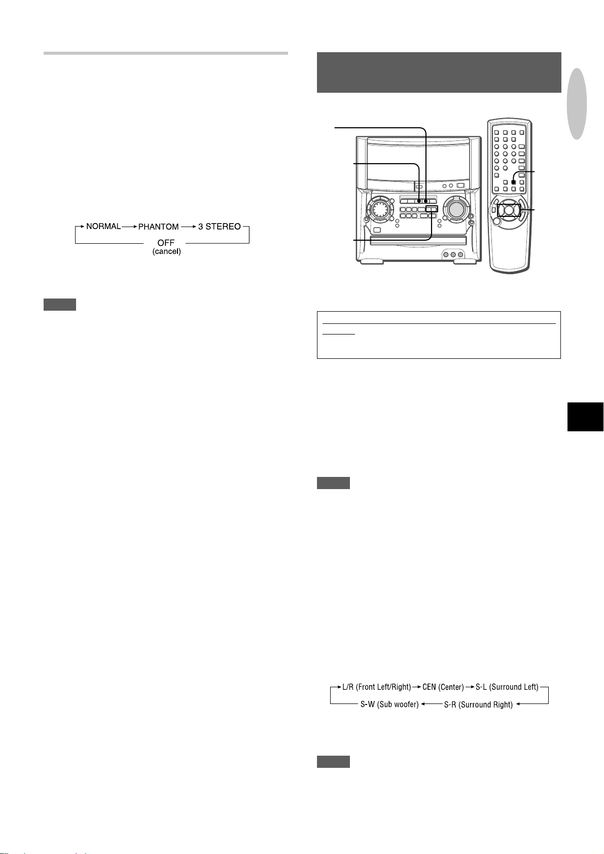
1
Press DOLBY PRO LOGIC to select NORMAL.
“NORMAL” is displayed.
If “PHANTOM” or “3 STEREO” is displayed, press DOLBY
PRO LOGIC repeatedly until “NORMAL” is selected.
En
ENGLISH
23
Page 25

2
Press MANUAL SELECT and hold it down for
about 4 seconds until “L” flashes.
PLAY WITH DOLBY PRO LOGIC
AUX/
PHONO/
5.1CH
A noise signal is sent to each channel in turn in the following
sequence.
3
Adjust the sound level of the center and the
surround speakers.
ff
While “CEN”, “S-R” or “S-L” is displayed, press
adjust the volume of the center or surround speakers to match
the level of the left and right speakers.
T o adjust the balance between the left and right front speakers ,
see page 11.
4
Press MANUAL SELECT again to stop the noise
f or
ff
gg
g to
gg
signal.
NOTE
• If the surround speakers or the center speaker level of the
DOLBY PRO LOGIC is changed, that of the DSP SURROUND
system (page 13) and the DOLBY DIGIT AL SURR OUND (page
25) is also changed.
• While “S-R” or “S-L” is display ed, both surround speakers output
the noise signal together. Howe ver, only the sound level of one
surround speaker displayed as “S-R” or “S-L” can be adjusted.
• When the sequencer outputs a noise signal, a clicking sound
might be heard from the speakers due to the characteristics of
the circuit. This is not malfunction.
VIDEO 1/2/3
f,g
1
Press VIDEO 1/2/3 or AUX/PHONO/5.1CH. Then
MANUAL
SELECT
f,g
start playback of the video source.
2
Press DOLBY PRO LOGIC.
NORMAL is selected, and the playback sound has the DOLBY
PRO LOGIC effect.
To cancel DOLBY PRO LOGIC mode
Press DOLBY PRO LOGIC repeatedly until “OFF” is displayed.
To change the sound levels during playback
After adjusting the balance with the noise sequencer, the sound
levels of the center or surround speak ers can be adjusted during
playback of laser discs or video software.
1 Press MANUAL SELECT on the remote control repeatedly
to select “CEN” (center), “S-R” (surround right) or “S-L”
(surround left).
2 While the “CEN”, “S-R” or “S-L” is displayed, press f or
g on the remote control to adjust the volume.
About the channels
The left and right speakers create the stereo effect.
The center speaker helps achieve precise sound positioning
over a broad sound field.
The surround speakers enhance the “depth” of the sound field.
To change the delay time
The surround speakers reproduce sounds a split second after
the front speakers. The dela y is initially set to 20 ms (milliseconds).
To change this standard delay time, press MANUAL SELECT
on the remote control repeatedly in NORMAL or PHANTOM mode
ff
until “TIME” is displayed. Then, press the
one of the buttons is pressed, the delay time changes as shown
below.
lj lj15ms 20ms 30ms
24
ENGLISH
f or
ff
gg
g. Each time
gg
Page 26
ADDITIONAL DOLBY PRO LOGIC MODES
In addition to the NORMAL mode, this unit is also equipped with
the PHANTOM and the 3 STEREO modes.
PHANTOM mode: Use this mode when no center speaker is
connected. The center channel signals are output through the
left and right speakers.
3 STEREO mode: Use this mode when no surround speakers
are connected. This mode reproduces rear sounds through the
front speakers.
To select PHANTOM or 3 STEREO
Press DOLBY PRO LOGIC repeatedly until the desired DOLBY
PRO LOGIC mode is displayed. The DOLBY PRO LOGIC mode
is displayed cyclically as follows.
T o adjust the balance of connected speaker sound levels
Carry out steps 2 to 4 on page 23.
NOTE
• Depending on the sound source and/or listening conditions,
surround effect may not be obtained even when the DOLBY
PRO LOGIC is on.
• The full DOLBY PRO LOGIC effect cannot be obtained when
using software without H mark. In this case, use
the DSP SURROUND system instead (see page 13).
• The DOLBY PRO LOGIC is automatically canceled when:
- the ECHO is turned on.
- the DSP SURROUND system or the BBE is turned on.
- the headphones are plugged in.
-the Karaoke function is turned on.
- the 5.1CH (page 25) is turned on.
• Set the microphone volume to OFF while the DOLBY PRO
LOGIC is on. Otherwise, the DOLBY PR O LOGIC sound cannot
be reproduced correctly.
When too high signals are input
When input analog signals from the connected equipment are
too high to accept,
the display lights up.
In this case, turn down the input level. If not, erroreous
operation will be carried out in the processor.
l on the left of "DOLBY PRO LOGIC" in
LISTENING TO DOLBY DIGITAL
SURROUND SOUND
AUX/
PHONO/
5.1CH
VIDEO 1/2/3
f,g
Preparation
Complete the connection on page 8 at first.
When a DVD player is connected to 5.1CH INPUT jacks of
this unit, you can listen to DOLBY DIGITAL SURROUND
sound, which enables you to enjoy theater-quality sound in
your home.
1
Press AUX/PHONO/5.1CH repeatedly until “5.1ch
IN” is displayed.
DOLBY DIGITAL SURROUND is turned on.
2
Press f or g to adjust the input level while
“5.1ch IN” is displayed.
The input level can be selected from MIN (0) to MAX (7).
3
Start playing DOLBY DIGIT AL SURROUND sound
on the DVD player.
NOTE
• The DOLBY PRO LOGIC, the BBE, the DSP SURROUND
system, Karaoke function, MIC and ECHO are automatically
canceled when the 5.1CH is selected.
• Make sure the software played back with the connected
equipment support the DOLBY DIGITAL SURROUND.
• The function is changed from the 5.1CH to the AUX when:
- the headphones are plugged in.
- the DSP SURROUND system, the DOLBY PRO LOGIC or
the Karaoke function is turned on.
- the MIC or ECHO level is changed.
T o adjust the sound levels of the speakers while listening
to the source (DOLBY DIGITAL SURROUND)
1 Press AUX/PHONO/5.1CH repeatedly until “5.1ch IN” is
displayed.
DOLBY DIGITAL SURROUND is turned on.
2 Press MANUAL SELECT on the remote control repeatedly.
Speaker name appears in turn as follows:
MANUAL
SELECT
f,g
DOLBY SURROUND
En
3 Press f or g to adjust the sound le vel while “L/R”, “CEN”,
“S-L”, “S-R” or “S-W” is displayed.
4 Repeat steps 2 and 3 to adjust each speaker’s sound level.
NOTE
If the surround speakers or the center speaker le vel of the DOLBY
DIGIT AL SURR OUND is changed, that of the DSP SURR OUND
system (page 13) and the DOLBY PRO LOGIC (page 24) is also
changed.
ENGLISH
25
Page 27

KARAOKE
MICROPHONE MIXING
Function
buttons
Two microphones (not supplied) can be connected to this unit,
allowing you to sing along to music sources.
Use microphones with standard plugs (ø6.3 mm,
Before connecting a microphone
Press MIC and turn VOLUME countercloc kwise until “MIC OFF”
is displayed.
1
Connect your microphones to MIC 1 and MIC 2
jacks.
VOLUMEVOLUME
MIC 1/2
MIC
ECHO
KARAOKE
1
/4 inch).
To change the delay time of echo
Hold down ECHO while the echo is on. “ECHO-L” (Long) and
“ECHO-M” (Middle) are displayed alternately. At the desired
position, release the button.
To record microphone sound mixed with source sound
Follow the procedure for recording from the sound source (see
page 20).
When the microphones are not in use
Set the microphone volume and echo level to OFF and remove
the microphones from MIC jacks.
NOTE
• ECHO is reset to OFF automatically when the function is
changed, the DOLBY PRO LOGIC or one of the DSP
SURROUND mode b uttons is pressed, the power is turned off,
or the AC cord is disconnected.
• If the MIC or ECHO is turned on while the 5.1CH (page 25) is
selected, the 5.1CH is changed to the AUX.
• When the ECHO level is changed, the DSP SURROUND
system and the DOLBY PRO LOGIC are automatically
canceled.
• If a microphone is held too near the speakers, a howling sound
may be produced. In this case, hold the microphone aw ay from
the speakers, or decrease the microphone volume.
• If sound through the microphone is extremely loud, it may be
distorted. In this case, decrease the microphone volume.
Recommended microphones
Use of unidirectional type microphones is recommended to
prevent howling. Contact your local Aiwa dealer for details.
2
Press one of the function buttons to select the
source to be mixed, and play the source.
3
Adjust the volume and tone of the source.
4
Press MIC and turn V OLUME within 4 seconds to
adjust the microphone volume.
The microphone volume can be selected from 1 to MAX (7)
or OFF (cancel).
The volume of both microphones is adjusted simultaneously.
5
Press ECHO and turn V OLUME within 4 seconds
to adjust the echo level.
The echo level can be selected from 1 to MAX (7) or OFF
(cancel).
26
ENGLISH
Page 28

VOCAL FADER/MULTIPLEX FUNCTIONS
This unit can use discs or tapes as Karaoke sources.
• Use the vocal fader function for ordinary discs or tapes.
• Use the multiplex function for multi audio discs or tapes.
Press KARAOKE repeatedly to select the v ocal fader
or multiplex function.
Each time KARAOKE is pressed, one of the follo wing functions
is selected cyclically.
1
2
3
4
To change the time lag setting in Auto Vocal Fader or
Auto Multiplex function
The muted original singer’s voice can be turned faster than the
normal level.
When Auto Vocal Fader or Auto Multiplex is selected, “A-VF” or
“A-MPX” is displayed for 3 seconds and disappears. Then hold
down KARAOKE until “FAST” is displayed.
To return to the initial setting, select SLOW.
When the power is turned off, SLOW is restored.
To change the audible channel in Multiplex function
Only the sound on the right channel can be heard from both
speakers.
When Multiplex is selected, “MPX-L” is displayed for 3 seconds
and disappears. Then the selected function name is displayed,
hold down KARAOKE until “MPX-R” is displayed.
To return to the initial setting, select MPX-L.
When the power is turned off, MPX-L is restored.
NOTE
• The Karaoke functions may not operate correctly with the
following kinds of CDs or tapes.
- Those with monaural sound
- Those recorded with strong echoes
- Those with the vocal part recorded on the right or left side of
the sound
• While the Karaoke function is on, the sound is output as
monaural.
• When the function is changed, the power is turned off or the
AC cord is disconnected from the AC po wer outlet, the Karaoke
function is canceled.
KARAOKE
5
1 Vocal Fader
The singer’s voice becomes softer than the accompaniment.
2 Auto Vocal Fader
The singer’s voice becomes softer only while there is audio
input through a microphone.
3 Multiplex
Only the sound on the left channel is heard from both
speakers, and the sound on the right channel is muted.
4 Auto Multiplex
The sound on the left channel is heard from both speakers,
and the sound on the right channel is muted only while there
is audio input through a microphone.
5 Cancel
En
ENGLISH
27
Page 29

CD KARAOKE PROGRAM
5
Press d to start play.
After a track is played, it is cleared from the program.
Track number of
the last reservation
Currently playing
track number flashes.
CD EDIT/
CHECK
0-9,+10
DISC DIRECT
PLAY
Before or during CD play, you can reserve up to 15 tracks to be
played after the current trac k. Each reservation is cleared when
it finishes playing.
Use the remote control.
1
Press CD and load the discs.
2
Press PRGM once.
After “CD KARAOKE” scrolls on the display , “K-P00” appeares.
PRGM
CD
c/d
g
s
Disc number of the
last reservation
To add a reservation during play
Repeat step 3.
To check the reserved tracks
Press CD EDIT/CHECK repeatedly. Each time it is pressed, the
disc number and track number are displayed in the reserved
order.
To stop play
Press s. When d is pressed, the play starts from the last
track again.
To skip a track
Press g.
The skipped track is cleared from the program.
Number of remaining
reserved tracks
Currently
playing disc
3
Press DISC DIRECT PLAY, then press one of the
numbered buttons 1-3 within 3 seconds to select
a disc. Then, press the numbered buttons 0-9 and
+10 to select a track.
Reserved
disc number
4
Repeat step 3 to reserve other tracks.
Reserved track
number
To clear all the reservations
Press g repeatedly until “K - P00” is displayed.
Press it once more to cancel the Karaoke programs. The displa y
returns to that of CD play.
NOTE
• If the reserved track number does not exist on the selected
disc, the unit stops playing and the display flashes.
In this case, press g to skip the error track. Then press d
to start play with the next reserved track.
• When PRGM is pressed twice in step 2, “– – 0:00” is displa yed
and the unit enters CD programmed play mode (page 19).
To cancel programmed play, press s.
28
ENGLISH
Page 30

CLOCK AND TIMER
SETTING THE CLOCK
CLOCK
s
a
MULTI
JOG
ENTER
CLOCK
f,g
When the clock is set, the “:” between the hours and minutes
flashes. When the clock setting is canceled due to a power failure,
the entire clock display flashes.
1
Press CLOCK.
f,g
a
SETTING THE SLEEP TIMER
MULTI
JOG
f,g
The unit can be turned off automatically at a specified time.
1
Press SLEEP on the remote control.
SLEEP
SLEEP
f,g
KARAKE
CLOCK AND TIMER
2
Within 4 seconds, turn MULTI JOG to designate
the hour and the minute.
Turning MULTI JOG changes both the hour and the minute.
f or g is also available instead of MULTI JOG. Holding
these buttons down will vary the time rapidly.
3
Press ENTER or a.
The clock starts from 00 seconds.
To view the clock when another displa y is in the display
Press CLOCK. The time is displa y ed for 4 seconds and then the
original display reappears. However, the clock cannot be
displayed during recording.
To switch to the 24-hour standard
Press CLOCK and then press s within 4 seconds.
Repeat the same procedure to restore the 12-hour standard.
In the 12-hour standard, "AM12:00" indicates midnight and
"PM12:00" indicates noon.
If the clock display flashes
If the display flashes when the clock is displa yed, it indicates
that the clock has stopped due to a power failure or the
removal of the power cord. The current time needs to be reset.
NOTE
If the power-economizing mode (page 10) is on, all the display
lights turn off when the power is turned off. To view the clock,
press CLOCK so that the time is displayed for 4 seconds.
2
Within 4 seconds, turn MULTI JOG or press f
or g to specify the time until the power is
turned off.
The time changes between 5 and 240 minutes in 5-minute
steps.
Specified time
To check the time remaining until the power turns off
Press SLEEP once. The remaining time is displayed for 4
seconds.
To cancel the sleep timer
Press SLEEP twice so that “SLEEPoFF” appears.
En
ENGLISH
29
Page 31

SETTING THE TIMER
VOLUME
Function
buttons
TIMER
MULTI
JOG
ENTER
POWER
TIMER
Function
buttons
VOL /
f,g
5
Adjust the volume.
The source sound will play at the volume level set in this step
when the power is turned on by the timer.
If the volume level is set to 21 or higher, however, it will
automatically be set to 20 when the power is turned on.
6
Prepare the source.
To listen to a CD, load the disc to be played first on tray 1.
To listen to a tape, insert the tape into the cassette tray.
T o listen to the radio, select the band and tune in to a station.
7
Press POWER to turn off the power.
remains on the display after the power is turned off (timer
standby mode) if the power-economizing mode is OFF.
a
f,g
The unit can be turned on at a specified time every day with the
built-in timer.
Preparation
Make sure the clock is set correctly.
1
Press one of the function buttons to select a
a
source.
2
Press TIMER once so that appears on the
display.
Time and audio source name flash alternately.
3
Within 6 seconds, turn MULTI JOG to designate
the timer-on time, then press ENTER or a.
Turning MULTI JOG changes both the hour and the minute.
f or g is also available instead of MULTI JOG. Holding
these buttons down will vary the time rapidly.
When the timer-on time is reached, the unit turns on and
begins play with the selected source.
To check the timer setting
Press TIMER.
The selected source, the timer-on time, and the duration for the
timer-activated period will be displayed for 6 seconds.
To change any of the previous setting
Carry out from step 1.
However, if you do not change the timer-on time, in step 3 just
press ENTER twice and continue from step 4.
To cancel the timer standby mode temporarily
Press TIMER repeatedly until disappears and “ OFF” is
displayed.
To restore the timer standby mode, press TIMER once or twice
to display or REC.
Using the unit while the timer is set
You can use the unit normally after setting the timer.
Before turning off the power, carry out step 5 and 6.
NOTE
• You can change the source that was selected in step 1 by
pressing one of the function buttons before pressing ENTER
or a in step 3.
• If the power-economizing mode is ON,
the timer standby mode.
• Timer playback and timer recording will not begin unless the
power is turned off.
• Connected equipment cannot be turned on and off by the builtin timer of this unit. Use an external timer.
is not displayed in
4
Within 4 seconds, turn MULTI JOG to select the
duration for the timer-activated period.
The duration can be set between 5 and 240 minutes in 5minute steps.
f or g is also available instead of MULTI JOG.
The duration will be automatically set after 4 seconds. It will
also be set if ENTER or a is pressed within 4 seconds after
step 4.
30
ENGLISH
Page 32

GENERAL
TIMER RECORDING
Timer recording is applicable for TUNER, VIDEO1/2/3 and A UX/
PHONO/5.1CH (with an external timer) sources only.
Press either TUNER/BAND, VIDEO1/2/3 or AUX/PHONO/
5.1CH to select a source, then press TIMER repeatedly until
REC appears on the display. Within 6 seconds, carry out
the steps of “SETTING THE TIMER” from step 3 and load the
tape to be recorded on into the cassette tray after step 6.
NOTE
• If the timer recording is done with the economizing mode (page
10) set to “ECO ON” or "ECO A UT O" and the po wer turns off,
the dimmer mode will be set to “DIMMER 3” and the volume
level will be 0 (minimum) level) the next time the power is
turned on.
• You cannot use the timer function to record from a CD.
• Y ou can chec k the timer setting by pressing TIMER e ven while
the power is off. In this case, if you press ENTER or a within
4 seconds after pressing TIMER, you can enter the timer
setting mode and change the previous setting.
CARE AND MAINTENANCE
Occasional care and maintenance of the unit and the software
are needed to optimize the performance of your unit.
To clean the cabinet
Use a soft dry cloth.
If the surfaces are extremely dirty, use a soft cloth lightly
moistened with mild detergent solution. Do not use strong
solvents, such as alcohol, benzine or thinner as these could
damage the finish of the unit.
To clean the tape heads
When the tape heads are dirty;
- high frequency sound is not emitted
- the sound is not adequately high
- the sound is off-balance
- the tape cannot be erased
- the tape cannot be recorded on
After every 10 hours of use, clean the tape heads with a head
cleaning cassette.
Refer to the instructions of the cleaning cassette for details.
To demagnetize the tape heads
The tape heads may become magnetized after long-term use.
This may narrow the output range of recorded tapes and increase
noise.
After every 20 to 30 hours of use, demagnetize the tape heads
with a separately sold demagnetizing cassette.
Refer to the instructions of the demagnetizing cassette for details.
CLOCK AND TIMER
GENERAL
Care of discs
• When a disc becomes dirty, wipe the disc from the center out
with a cleaning cloth.
• After playing a disc, store the disc in its case. Do not leave the
disc in places that are hot or humid.
Care of tapes
• Store tapes in their cases after use.
• Do not leave tapes near magnets, motors, television sets, or
any source of magnetism. This will do wngrade the sound quality
and cause noise.
• Do not expose tapes to direct sunlight, or leave them in a car
parked in direct sunlight.
En
ENGLISH
31
Page 33

SPECIFICATIONS
Main unit CX-A1000
FM tuner section
Tuning range 87.5 MHz to 108 MHz
Usable sensitivity (IHF)
Antenna terminals 75 ohms (unbalanced)
AM tuner section
Tuning range 530 kHz to 1710 kHz (10 kHz step)
Usable sensitivity 350 µV/m
Antenna Loop antenna
Amplifier section
Mid-high frequency amplifier
Power output
Rear (Surround)
Center 80 W (1 kHz, THD less than 1 %, 8 ohms)
Total harmonic distortion
LOW FREQ + SUB WOOFER amplifier
Power output
Total harmonic distortion
Inputs AUX: 310 mV
Outputs CD DIGITAL OUT (OPTICAL)
13.2 dBf
531 kHz to 1602 kHz (9 kHz step)
Front
80 W + 80 W
(200 Hz - 20 kHz, THD less than 1 %, 8 ohms)
100 W + 100 W
(200 Hz - 20 kHz, THD less than 10 %, 8 ohms)
80 W + 80 W
(1 kHz, THD less than 1 %, 8 ohms)
100 W + 100 W
(1 kHz, THD less than 10 %, 8 ohms)
100 W (1 kHz, THD less than 10 %, 8 ohms)
0.15 %
(40 W, 1 kHz, 8 ohms, DIN AUDIO/Front)
200 W + 200 W
(50 Hz - 200 Hz, THD less than 1 %, 6 ohms)
250 W + 250 W
(50Hz- 200 Hz, THD less than 10%, 6 ohms)
0.15 %
(100 W , 100 Hz, 6 ohms, DIN A UDIO/Front)
PHONO: 400 mV
VIDEO1, VIDEO2, VIDEO3: 310mV
5.1CH INPUT (adjustable)
FRONT: 300 mV
SURROUND: 300 mV
CENTER: 600 mV
SUB WOOFER: 300 mV
MIC 1, MIC 2: 1.4 mV (20 kohms)
SPEAKERS:
+ SUB WOOFER 6 ohms
LOW
HIGH 8 ohms
SURROUND SPEAKERS: accept
speakers of 8 -16 ohms
CENTER SPEAKER: accepts speakers
of 8 ohms or more
PHONES (stereo jack): accepts
headphones of 32 ohms or more
Cassette deck section
Track format 4 tracks, 2 channels stereo
Frequency response CrO
2 tape: 50 Hz – 16000 Hz
Normal tape: 50 Hz – 15000 Hz
Signal-to-noise ratio 60 dB (Dolby B NR ON, CrO
2 tape peak
level, above 400 Hz)
Recording system AC bias
Heads Recording/playback head × 1,
erase head × 1
Compact disc player section
Laser Semiconductor laser (λ = 780 nm)
D/A converter 1 bit dual
Signal-to-noise ratio 85 dB (1 kHz, 0 dB)
Harmonic distortion 0.03 % (1 kHz, 0 dB)
General
Power requirements 120 V AC, 60 Hz
Power consumption
300 W
Dimensions of main unit
360 × 372 × 423 mm
141/4 × 143/4 × 163/4 in.)
(
Weight of main unit 18.5 kg (40 lb. 12 oz)
Front speakers SX-WA1000
Cabinet type 4 way, built-in subwoofer
Speakers Subwoofer:
220 mm cone type
Woofer:
160mm cone type
Tweeter:
60 mm cone type
Super tweeter:
20 mm ceramic type
Impedance 6 ohms/ 8 ohms
Output sound pressure level
89 dB/W/m
Dimensions (W × H × D)
250 × 592 × 300 mm
97/8 × 233/8 × 117/8 in.)
(
Weight 11.7 kg (25 lb. 13 oz)
Surround speakers SX-R1800
Speakers Full-range:
100 mm × 1, cone type
Impedance 8 ohms
Dimensions (W × H × D) 120 × 230 × 175 mm
1
4
× 9
8
/
× 7 in.)
43/
(
Weight 1.9 kg (4 lb. 3 oz)
Center speaker SX-C1800
Speakers Full-range:
100 mm × 2, cone type
Impedance 8 ohms
Dimensions (W × H × D)
430 × 120 × 175 mm
4
17 × 43/
(
× 7 in.)
Weight 2.7 kg (5 lb. 15 oz)
32
Specifications and external appearance are subject to change
without notice.
ENGLISH
Page 34

COPYRIGHT
Please check the laws on copyright relating to recordings from
discs, radio or external tape for the country in which the machine
is being used.
TROUBLESHOOTING GUIDE
The word “BBE” and the “BBE symbol” are trademarks of BBE
Sound, Inc.
Under license from BBE sound, Inc.
DOLBY NR
Dolby noise reduction manufactured under license from Dolby
Laboratories Licensing Corporation.
“DOLBY” and the double-D symbol h are trademarks of Dolby
Laboratories Licensing Corporation.
DOLBY PRO LOGIC
Manufactured under license from Dolby Laboratories Licensing
Corporation.
“DOLBY”, the double-D symbol h and “PRO LOGIC” are
trademarks of Dolby Laboratories Licensing Corporation.
NOTE
This equipment has been tested and found to comply with the
limits for a Class B digital device, pursuant to P art 15 of the FCC
Rules. These limits are designed to provide reasonab le protection
against harmful interference in a residential installation.
This equipment generates, uses, and can radiate radio frequency
energy and, if not installed and used in accordance with the
instructions, may cause harmful interference to radio
communications. Howev er, there is no guar antee that interference
will not occur in a particular installation. If this equipment does
cause harmful interference to radio or television reception, which
can be determined by turning the equipment off and on, the user
is encouraged to try to correct the interference by one or more
of the following measures:
- Reorient or relocate the receiving antenna.
- Increase the separation between the equipment and
receiver.
- Connect the equipment into an outlet on circuit different from
that to which the receiver is connected.
- Consult the dealer or an experienced radio/TV technician
for help.
CAUTION
Modifications or adjustments to this product, which are not
expressly approved by the manufacturer, may void the user’s
right or authority to operate this product.
To reset
If an unusual condition occurs in the display window or the
cassette decks, reset the unit as follows.
1 Press POWER to turn off the power.
2 Press POWER to turn the power back on while pressing
sCLEAR. Everything stored in memory after purchase is
canceled.
If the power cannot be turned off in step 1 because of a
malfunction, reset by disconnecting the AC cord, and connect it
again. Then carry out step 2.
If the unit fails to perform as described in these Operating
Instructions, check the following guide.
GENERAL
There is no sound.
• Is the AC cord connected properly?
• Is there a bad connection? (b page 4)
• There may be a short circuit in the speaker terminals.
b Disconnect the AC cord, then correct the speaker
connections.
• Was an incorrect function button pressed?
• No sound is heard from the center and surround speakers when
the DOLBY PRO LOGIC, the DSP SURROUND system and
the 5.1CH are set to off. (b pages 13, 23)
There is no sound from the center and surround speakers
when you use the DOLBY PRO LOGIC.
• Are the DSP SURROUND system and the 5.1CH set to off?
(b pages 13, 23) )
Sound is emitted from one speaker only.
• Is the other speaker disconnected?
The output sound is not stereo.
• Is the Karaoke function turned on? (b page 26)
An erroneous display or a malfunction occurs.
b Reset the unit as stated below.
The unit blacks out when the power is off.
• Is the power economizing mode set to "ECO ON" or "ECO
AUTO"? (b page 10)
The power is not turned on.
• Disconnect the AC cord, and connect it again in a f ew seconds.
TUNER SECTION
There is constant, wave-like static.
• Is the antenna connected properly? (b page 5)
• Is the signal weak?
b Connect an outdoor antenna.
The reception contains noise interferences or the sound
is distorted.
• Is the system picking up external noise or multipath distortion?
b Change the orientation of the antenna.
b Move the unit away from other electrical appliances.
CASSETTE DECK SECTION
The tape does not run.
• Is the deck in pause mode? (b page 16)
The sound is off-balance or not adequately high.
• Is the playback head dirty? (b page 31)
Recording is not possible.
• Is the erasure prevention tab on the tape broken off?
(b page 23)
• Is the recording head dirty? (b page 31)
Erasure is not possible.
• Is the erasure head dirty? (b page 31)
• Is a metal tape being used?
High frequency sound is not emitted.
• Is a tape recorded without Dolby NR played back with the Dolby
NR system operating? (b page 16)
• Is the playback head dirty? (b page 31)
CD PLAYER SECTION
The CD player does not play.
• Is the disc correctly placed? (b page 17)
• Is the disc dirty? (b page 31)
• Is the lens affected by condensation?
b Wait approximately one hour and try again.
GENERAL
En
ENGLISH
33
Page 35

PARTS INDEX
1
2
3
INDICE DE LAS PARTES
9
0
NOMENCLATURE
^
&
-
*
=
4
5
6
7
8
Name/Nombre/Nom Page/Página/Page
1 Display window
2 Function buttons
PHONO/5.1CH, CD) ........
3 Cassette tray
4 MUL TI JOG.........................9, 10, 12-15, 17, 29, 30
GEQ ....................................12
SURROUND .......................13
FL DISPLAY .......................9, 10
TUNER PRESET ................14, 15
TIMER.................................30
ECO ....................................10
ENTER................................10, 13, 29, 30
GEQ FREQ (LOW) .............12, 13
GEQ FREQ (HIGH).............12, 13
5 PHONES .............................11
6 POWER...............................9, 14, 30
7 CLOCK ...............................10, 29
DEMO .................................9
8 CD tray ...............................17
9 zTAPE OPEN/CLOSE ......16
0 DOLBY NR .........................20
REV MODE.........................16, 20
DOLBY PRO LOGIC ..........23-25
! BBE ....................................11
T-BASS ...............................11
MIC .....................................26
ECHO..................................26
VOLUME.............................11, 26, 30
@ MIC1 ...................................26
MIC2 ...................................26
# CD BLANK SKIP................19
KARAOKE..........................27
$ wREC/REC MUTE.............20-22
aSET .................................15-17, 20, 29, 30
sCLEAR............................15-17, 19-22, 28, 29
dDIRECTION/PRESET ...
(T APE, TUNER, VIDEO1/2/3,AUX/
8, 9, 14-17, 20, 24, 25
15-19, 28
!
@
#
(
)
[
]
$
%
Name/Nombre/Nom Page/Página/Page
f/r(DOWN)...............11-17, 19, 21-25, 29, 30
g/t(UP) .....................11-17, 19, 21-25, 28-30
DISC DIRECT PLAY 1-3 .....17-19, 21, 22, 28
DISC CHANGE...................17
zCD OPEN/CLOSE ..........17
% VIDEO 3 IN, AUDIO IN (L,R) 7
^ TIMER .................................14, 30
SLEEP ................................29
MONO TUNER....................14
CLOCK ...............................10, 29
CD EDIT/CHECK ................17, 21, 22, 28
PRGM .................................19, 28
RANDOM/REPEA T.............18, 19
& 0-9,+10................................15-17, 19, 21, 22, 28
* DISC DIRECT PLAY 1-3.....17-19, 21, 22, 28
( qREC/REC MUTE ........20-22
aSET .................................15-17, 20, 29, 30
) POWER...............................9, 14, 30
- TAPE...................................16
TUNER/BAND ....................14, 15
AUX/PHONO ......................8, 24, 25
CD.......................................17
VIDEO 1/2/3........................8
= SURROUND .......................13
MANUAL SELECT .............11, 13, 24, 25
hPRO LOGIC...................23-25
T-BASS ...............................11
GEQ ....................................12
KARAOKE..........................27
zCD OPEN/CLOSE ..........17
[ VOL(
] c/dPRESET .................15-19, 21, 22, 28
N,M
) .........................11, 26, 30
sCLEAR............................15-17, 19-22, 28, 29
f/r(DOWN)...............11-17, 19, 21-25, 29, 30
g/t(UP) .....................11-17, 19, 21-25, 28-30
For assistance and information
call toll free 1-800-BUY-AIWA
Printed in Malaysia
(United States and Puerto Rico)
Page 36

XH-A1000
CORRECTION
Please read the incorrect description in the
Operating Instructions as follows.
Page 21
AI EDIT RECORDING
WRONG
6
Press q REC/REC MUTE to start
recording.
RIGHT
6
Press qREC/REC MUTE and then press
c /d within 2 seconds to start
recording.
Page 22
PROGRAMMED EDIT
RECORDING
WRONG
8
Press q REC/REC MUTE to start
recording.
RIGHT
8
Press qREC/REC MUTE and then press
c /d within 2 seconds to start
recording.
CORRECCION
Interprete, porfavor, las descripciones
incorrectas del manual de la forma sigulente.
Página 21
GRABACIÓN DE EDICIÓN AI
ERRONEO
6
Presione qREC/REC MUTE para iniciar
la grabación.
ORRECTO
6
Presione q REC/REC MUTE y luego
pulse c /d antes de que pasen 2
segundos para iniciar la grabación.
Página 22
GRABACIÓN DE EDICIÓN
PROGRAMADA
ERRONEO
8
Presione qREC/REC MUTE para iniciar
la grabación.
ORRECTO
8
Presione q REC/REC MUTE y luego
pulse c /d antes de que pasen 2
segundos para iniciar la grabación.
CORRECTION
Prière d’apporter les corrections suivantes au
mode d’emploi.
Page 21
ENREGISTREMENT PAR
MONTAGE INTELLIGENT
MAUVAIS
6
Appuyez sur qREC/REC MUTE pour
lancer l’enregistrement.
BON
6
Appuyez sur qREC/REC MUTE puis
appuyer sur c/d dans les 2 secondes
qui suivent pour lancer l’enregistrement.
Page 22
ENREGISTREMENT PAR
MONTAGE PROGRAMME
MAUVAIS
8
Appuyez sur qREC/REC MUTE pour
lancer l’enregistrement.
BON
8
Appuyez sur qREC/REC MUTE puis
appuyer sur c/d dans les 2 secondes
qui suivent pour lancer l’enregistrement.
8A-MTM-919-01
0001A-Y
Printed in Japan
Page 37

ESPAÑOL
ADVERTENCIA
PARA REDUCIR EL RIESGO DE INCENDIO O
DESCARGA ELÉCTRICA, NO EXPONGA ESTE
APARATO A LA LLUVIA NI A LA HUMEDAD.
CAUTION
RISK OF ELECTRIC SHOCK
DO NOT OPEN
“CAUTION:TO REDUCE THE RISK OF
ELECTRIC SHOCK,
DO NOT REMOVE COVER (OR BACK).
NO USER-SERVICEABLE PARTS INSIDE.
REFER SERVICING TO QUALIFIED
SERVICE PERSONNEL.”
Descripción de los símbolos gráficos:
Registro del propietario
Para su comodidad, anote los números de modelo y de serie
(situados en la parte trasera de la unidad) en el espacio
proporcionado a continuación. Téngalos presentes cuando se
ponga en contacto con el proveedor Aiwa en caso de dificultades.
Nº de modelo Nº de serie (nº de lote)
CX-A1000
SX-WA1000
SX-C1800
SX-R1800
El símbolo de rayo, incluido dentro de un triángulo
equilátero, está destinado a alertar al usuario sobre
la presencia de “tensión peligrosa” no aislada dentro
del producto, que puede ser de suficiente magnitud
como para constituir un riesgo de descarga eléctrica
para las personas.
El símbolo de exclamación, incluido en un triángulo
equilátero, está destinado a alertar al usuario sobre
la presencia de instrucciones importantes de empleo
y mantenimiento (servicio técnico) en la
documentación suministrada con el aparato.
PRECAUCIONES
Lea el manual de instrucciones atentamente y por completo
antes de emplear la unidad. Asegúrese de conservar el manual
de instrucciones para consultarlo en el futuro. Todas las
advertencias y precauciones proporcionadas en el manual de
instrucciones y en la unidad deben respetarse estrictamente,
así como los siguientes consejos sobre seguridad.
Instalación
1 Agua y humedad — No emplee esta unidad cerca del agua,
como por ejemplo, cerca de una bañera, pileta de la cocina,
piscina o similares.
2 Calor — No utilice esta unidad cerca de fuentes de calor,
incluidas salidas de calefacción, estufas u otros dispositivos
que generen calor.
Tampoco debe situarse en lugares cuya temperatura sea
inferior a 5°C (41°F) o superior a 35°C (95°F).
3 Superficie de montaje — Instale la unidad sobre una
superficie plana y nivelada.
4 Ventilación — La unidad debe instalarse con suficiente
espacio a su alrededor de forma que el calor se disperse.
Deje un espacio libre de 10 cm en las partes posterior y
superior de la unidad, y de 5 cm a cada lado.
- No coloque el aparato sobre una cama, alfombra o superficie
similar que pueda bloquear las aberturas de ventilación.
- No instale la unidad en un estante para libros, mueble o
repisa cerrada que pueda impedir la circulación de aire.
5 Introducción de objetos y líquidos — Tenga cuidado para
que no se introduzcan objetos ni líquidos en la unidad a través
de las aberturas de ventilación.
6 Carros de mano y soportes — La unidad
debe moverse con cuidado cuando se
encuentre sobre un carro de mano o soporte.
Las paradas bruscas, la fuerza excesiva o las
superficies desniveladas pueden causar que
la unidad o el carro se caiga.
7 Condensación — Es posible que se condense humedad en
la lente del fonocaptor de CD si:
- La unidad se desplaza de un lugar frío a otro caliente
- El sistema de calefacción se pone en funcionamiento
- La unidad se emplea en una sala muy húmeda
- La unidad se refrigera mediante un acondicionador de aire
Si se condensa humedad en el interior de este aparato, es
posible que no funcione con normalidad. Si esto ocurre, no lo
utilice durante unas horas. A continuación, vuelva a emplearlo .
8 Instalación en la pared o en el techo — La unidad no debe
instalarse en la pared ni en el techo, a menos que se
especifique en el manual de instrucciones.
Alimentación eléctrica
1 Fuentes de alimentación — Conecte esta unidad
únicamente a las fuentes de alimentación especificadas en
el manual de instrucciones y en las etiquetas de la misma.
2 Polarización — Como medida de seguridad, algunas
unidades están equipadas con clavijas polarizadas de
alimentación de CA que sólo pueden insertarse en la toma
de corriente en una única posición. Si resulta difícil o imposible
insertar la clavija de alimentación de CA en la toma de
corriente, dele la vuelta a la clavija e inténtelo de nuevo. Si
aún así no puede insertarla con facilidad en la toma de
corriente, póngase en contacto con un técnico cualificado
para que repare o sustituya dicha toma. Con el fin de respetar
la característica de seguridad de la clavija polarizada, no la
fuerce para introducirla en la toma de corriente.
3 Cable de alimentación de CA
- Cuando desconecte el cable de alimentación de CA, tire
del enchufe del mismo. No tire del propio cable.
- No toque el enchufe de alimentación de CA con las manos
mojadas, ya que pueden producirse incendios o descargas
eléctricas.
- Los cables de alimentación deben instalarse
cuidadosamente con el fin de evitar que se doblen en
exceso, queden atrapados o se pisen. Preste especial
atención al cable que conecta la unidad a la toma de
corriente.
- Evite sobrecargar las tomas de CA y los cables
prolongadores más allá de su capacidad, ya que pueden
producirse incendios o descargas eléctricas.
4 Cable prolongador — Para evitar recibir descargas
eléctricas, no utilice una clavija polarizada de alimentación
de CA con un cable prolongador, receptáculo u otr a toma de
corriente, a menos que la clavija polarizada pueda insertarse
por completo y las cuchillas de la misma no queden al
descubierto.
5Períodos sin utilización — Cuando no vaya a utilizar la
unidad durante varios meses o más, desconecte el cable de
alimentación de CA de la toma de corriente. Mientr as el cable
esté enchufado, la unidad recibirá una pequeña cantidad de
corriente aunque la alimentación esté desactivada.
2
ESPAÑOL
Page 38

Antena exterior
1Líneas eléctricas — Cuando conecte una antena exterior,
asegúrese de instalarla alejada de líneas eléctricas.
2 Puesta a tierra de la antena exterior — Asegúrese de que
el sistema de antena está adecuadamente puesto a tierra
con el fin de obtener protección contra sobretensiones
inesperadas o acumulaciones de electricidad estática. El
Artículo 810 del NEC (National Electrical Code), ANSI/NFPA
70, proporciona información sobre la puesta a tierra apropiada
del poste, la estructura de soporte y el cable de entrada de la
unidad de descarga de antena, así como sobre el tamaño de
la unidad de puesta a tierra, la conexión a los terminales de
puesta a tierra y los requisitos para poner a tierra los propios
terminales.
Antenna Grounding According to the National Electrical Code
Puesta a tierra de la antena según el NEC (National Electrical Code)
CABLE DE ENTRADA
ANTENNA LEAD IN WIRE
DE ANTENA
ABRAZADERA
GROUND CLAMP
DE PUESTA A
TIERRA
EQUIPO DE
ELECTRIC
SERVICE
SERVICIO
EQUIPMENT
ELÉCTRICO
NEC-NATIONAL ELECTRICAL CODE
NEC-NATIONAL ELECTRICAL CODE
ANTENNA DISCHARGE
UNIDAD DE
UNIT
DESCARGA DE
(NEC SECTION 810-20)
ANTENA (SECCIÓN
810-20 DEL NEC)
CONDUCTORES DE
PUESTA A TIERRA
GROUNDING
CONDUCTORS
(SECCIÓN 810-21
(NEC SECTION 810-21)
DEL NEC)
ABRAZADERAS DE
GROUND CLAMPS
PUESTA A TIERRA
POWER SERVICE GROUNDING
SISTEMA DE ELECTRODOS
ELECTRODE SYSTEM
DE PUESTA A TIERRA DE
(NEC ART 250 PART H)
SERVICIO ELÉCTRICO
(ARTÍCULO 250 PARTE H DEL
NEC)
Mantenimiento
Limpie la unidad solamente como se recomienda en el manual
de instrucciones.
Averías que requieren asistencia técnica
Haga que un técnico cualificado repare las unidades si:
- El cable o la clavija de alimentación de CA está dañado
- Se han introducido objetos extraños o líquidos en la unidad
- La unidad ha estado expuesta a la lluvia o al agua
- La unidad no parece funcionar con normalidad
- La unidad muestra un cambio evidente en su rendimiento
- La unidad se ha caído o su exterior se ha dañado
EL PROPIO USUARIO NO DEBE INTENTAR REPARAR LA
UNIDAD.
ÍNDICE
PREPARATIVOS
COMPRUEBE EL SISTEMA Y LOS ACCESORIOS ......... 4
CONEXIONES BÁSICAS................................................... 4
CONEXIÓN DE OTROS EQUIPOS ................................... 6
CONEXIÓN DE UN REPRODUCTOR DE DVD .................8
CONTROL REMOTO...........................................................9
ANTES DE LA UTILIZACIÓN ............................................ 9
SONIDO
AJUSTES DE SONIDO .................................................... 11
ECUALIZADOR GRÁFICO .............................................. 12
DSP SURROUND............................................................. 13
RECEPCIÓN DE LA RADIO
SINTONIZACIÓN MANUAL ............................................. 14
MEMORIZACIÓN DE EMISORAS................................... 15
REPRODUCCIÓN DE CINTAS
OPERACIONES BÁSICAS .............................................. 16
REPRODUCCIÓN DE CD
OPERACIONES BÁSICAS .............................................. 17
REPRODUCCIÓN PROGRAMADA................................. 19
GRABACIÓN
GRABACIÓN BÁSICA ..................................................... 20
GRABACIÓN DE EDICIÓN AI ......................................... 21
GRABACIÓN DE EDICIÓN PROGRAMADA .................. 22
DOLBY SURROUND
AJUSTE DEL NIVEL DE LOS ALTAVOCES................... 23
REPRODUCCIÓN CON DOLBY PRO LOGIC ................ 24
AUDICIÓN DE SONIDO DOLBY DIGITAL
SURROUND ..................................................................... 25
KARAOKE
MEZCLA DE SONIDOS CON MICRÓFONOS ................ 26
PROGRAMA DE KARAOKE DE CD............................... 28
E
RELOJ Y TEMPORIZADOR
AJUSTE DEL RELOJ ...................................................... 29
AJUSTE DEL TEMPORIZADOR DE APAGADO ............ 29
AJUSTE DEL TEMPORIZADOR ..................................... 30
GENERAL
CUIDADOS Y MANTENIMIENTO .................................... 31
ESPECIFICACIONES....................................................... 32
GUÍA DE SOLUCIÓN DE PROBLEMAS ........................ 33
INDICE DE LAS PARTES ...........................
Contraportada
ESPAÑOL
3
Page 39

PREPARATIVOS
COMPRUEBE EL SISTEMA Y
LOS ACCESORIOS
XH-A1000
Receptor estéreo de casetes y discos compactos CX-A1000
Altavoces frontales SX-WA1000
Altavoz central SX-C1800
Altavoces de sonido envolvente SX-R1800
Control remoto Antena de AM Antena de FM
Manual de instrucciones, etc.
CONEXIONES BÁSICAS
El sistema DOLBY PRO LOGIC, característica principal de este
sistema estéreo, proporciona sonido multicanal en su propio
hogar. Conecte el TV o los equipos de video a esta unidad par a
disfrutar del sistema de “cine en casa” potenciado.
Realice el ajuste y la conexión de la unidad principal, de los
altavoces suministrados, del TV y de los equipos de video de
acuerdo con el siguiente procedimiento.
Antes de conectar el cable de CA
La tensión nominal de la unidad, indicada en el panel posterior,
es de 120 V CA. Compruebe que la tensión nominal coincide
con la local.
IMPORTANTE
Conecte primero los altavoces, las antenas y todos los equipos
opcionales. Después, conecte el cable de CA.
No existen diferencias entre los altavoces frontales y los de
sonido envolvente. Ambos altavoces de cada tipo pueden
conectarse como L (izquierdo) o R (derecho).
1
Conecte el altavoz derecho a la unidad principal.
1 Conecte el cable de altavoz con raya blanca al terminal
SPEAKERS LOW FREQ R 0 y el cable negro al terminal
9.
Altavoz de sonido envolvente
Altavoz derecho
Altavoz central
Antena de FM
Unidad principal
SPEAKER
IMP : 6Ω
Enrolle el extremo del cable alrededor del terminal. A
continuación, apriete el terminal. Compruebe que el cable
está correctamente conectado.
Altavoz de sonido envolvente
Antena de AM
Altavoz izquierdo
4
ESPAÑOL
Cable de altavoz
Cable de CA
Page 40

2 Conecte el cable de altavoz de color azul a la toma
SPEAKERS HIGH FREQ R.
S
R
E
K
A
E
P
S
HIGH FREQ
2
Conecte el altavoz izquier do a la unidad principal.
R
E
K
A
E
P
S
HIGH FREQ
S
Conecte el cable de altavoz de color azul al terminal
SPEAKERS HIGH FREQ L, y el otro cable de altavoz a los
terminales SPEAKERS LOW FREQ L de la misma forma
que en el paso 1.
3
Conecte los altavoces de sonido envolvente a la
unidad principal.
Conecte el cable del altavoz de sonido envolvente derecho
al terminal SURROUND SPEAKERS R, y el izquierdo al
terminal SURROUND SPEAKERS L.
Para colocar las antenas
Antena de FM:
Extienda la antena horizontalmente en forma de T y fije sus
extremos a la pared.
Antena de AM:
Coloque esta antena y gírela de forma que obtenga la mejor
recepción posible.
Para colocar la antena de AM sobre una superficie
Fije la uña a la ranura.
COLOCACIÓN DE LOS ALTAVOCES
Para obtener los mejores efectos posibles del sistema DOLBY
PRO LOGIC, es importante que coloque los altavoces
adecuadamente.
Consulte la siguiente ilustración para obtener la mejor ubicación
posible en la sala.
PREPARATIVOS
4
Conecte el altavoz central.
Conecte el cable del altavoz central al terminal CENTER
SPEAKER.
5
Conecte las antenas suministradas.
Conecte la antena de FM a los terminales FM 75 Ω y la de
AM a los terminales AM LOOP.
Antena de FM
Antena de AM
6
Conecte los otros equipos.
Es posible conectar a esta unidad determinados equipos de
audio y video (reproductor de LD, reproductor de MD,
reproductor de DVD, TV, etc.).
Para obtener información detallada, consulte la página 6.
7
Conecte el cable de CA a una toma de CA.
La demostración (DEMO) se activará al conectar el cable de
CA a una toma de CA por primera vez tras la adquisición del
producto. Para desactivar la demostración, ajuste el reloj.
12 1
3
E
3
1 Altavoces frontales
2 Altavoz central
Coloque los dos altavoces frontales en la parte central. Si
conecta un TV a la unidad, coloque los altav oces por encima
o por debajo del TV.
3 Altavoces de sonido envolvente
Sitúe los altavoces de sonido envolvente directamente a los
lados del área de audición o ligeramente por detrás de ésta.
Alinéelos horizontalmente, aproximadamente 1 metro por
encima de la altura de los oídos.
NOTA
• No se oirá el sonido de los altavoces central y de sonido
envolvente si los sistemas DOLBY PRO LOGIC, DSP
SURROUND y de 5,1 canales (5.1CH) (página 25) están
desactivados.
• El sonido se oirá por el altavoz central si DOLBY PR O LOGIC
o 5.1CH (página 25) está activado.
ESPAÑOL
5
Page 41

Para instalar los altavoces de sonido envolvente en la
pared
Utilice tornillos de instalación en pared (no suministrados).
Seleccione un lugar que pueda soportar el peso de los altavoces
e instálelos cuidadosamente de forma que queden firmemente
asegurados.
Aiwa rechaza toda
responsibilidad por daños
a personas y demás
accidentes causados por
la instalación inadecuada
de los altavoces de sonido
envolvente o debidos a
que el lugar de instalación
no sea el apropiado.
NOTA
• Asegúrese de conectar los cables de
los altavoces correctamente. El
contacto de conductores desnudos
con otras tomas o con otros
conductores puede causar
cortocircuitos en los terminales
R
E
K
A
E
P
S
Ω
6
:
P
M
I
SPEAKERS o fallos de funcionamiento.
• No deje objetos que generen magnetismo, como tarjetas de
créditos, cerca de los altavoces, y a que dichos objetos podrían
dañarse.
• No acerque la antena de FM a objetos metálicos ni a raíles de
cortinas.
• No acerque la antena de AM a otros equipos opcionales, al
propio sistema estéreo, al cable de CA ni a los cables de los
altavoces, ya que se producirá ruido.
• No desenrolle el cable de la antena de AM.
CONEXIÓN DE UNA ANTENA EXTERIOR
Con el fin de mejorar la recepción de FM, se recomienda utilizar
una antena exterior. Conecte la antena exterior a los terminales
FM 75 Ω.
T omas VIDEO2/LD/TV
Puede conectar un equipo de video, un reproductor de LD o TV
por cable, etc., a estas tomas.
• Utilice cables de audio y video disponibles en el mercado.
• Para que esta unidad reciba las señales del equipo conectado ,
conecte los cables a las tomas VIDEO2/LD/TV IN.
Para que el equipo conectado reciba las señales de esta
unidad, conecte los cables a las tomas VIDEO2/LD/TV OUT.
• Conecte la salida L (izquierda) del equipo conectado y AUDIO
L de esta unidad, y la salida R (derecha) y AUDIO R mediante
el cable de audio.
T omas VIDEO3
Puede conectar un equipo de video, una cámara de video o una
consola de juegos de TV, etc., a estas tomas. Gire VOLUME a
“0” antes de conectar cualquier equipo a las tomas VIDEO 3.
• Utilice cables de audio y video disponibles en el mercado.
• Conecte la salida L (izquierda) del equipo conectado y AUDIO
IN L de esta unidad, y la salida R (derecha) y AUDIO IN R
mediante el cable de audio.
• Conecte la salida de video del equipo conectado y VIDEO IN
de esta unidad mediante el cable de video.
Tomas REC OUT/AUDIO MONITOR
Puede conectar un equipo de grabación (como una grabadora
de MD, una grabadora de CD-R/RW, una platina de casetes o
un TV, etc.) a estas tomas.
Igualmente, es posible grabar o controlar el sonido del equipo
conectado a VIDEO1/DVD/MD o VIDEO2/LD/TV.
• Utilice un cable de audio disponible en el mercado.
• Conecte la salida L (izquierda) del equipo conectado y AUDIO
L de esta unidad, y la salida R (derecha) y AUDIO R mediante
el cable de audio.
Tomas MONITOR/VIDEO OUT
Puede conectar un TV, etc., a estas tomas.
Es posible ver la imagen del equipo conectado a VIDEO1/DVD/
MD o VIDEO2/LD/TV.
• Utilice un cable de video disponible en el mercado.
Toma CD DIGITAL OUT (OPTICAL)
Puede conectar un equipo digital, como una grabadora de MD,
una platina DAT, una platina digital de casetes o un amplificador
digital, etc., a esta toma. Las señales digitales del reproductor
de CD de esta unidad se envían al equipo conectado.
• Utilice un cable óptico disponible en el mercado.
• Antes de conectar el cable óptico, retire la tapa contra polvo
a de la toma CD DIGITAL OUT (OPTICAL).
CONEXIÓN DE OTROS EQUIPOS
Es posible conectar un equipo de video, un TV, un reproductor
de LD, un reproductor de DVD o un reproductor de MD, etc., a
esta unidad.
Tomas VIDEO1/D VD/MD
Puede conectar un equipo de video, un reproductor de DVD o
un reproductor de MD, etc., a estas tomas.
• Utilice cables de audio y video disponibles en el mercado.
• Para que esta unidad reciba las señales del equipo conectado ,
conecte los cables a las tomas VIDEO1/DVD/MD IN.
Para que el equipo conectado reciba las señales de esta
unidad, conecte los cables a las tomas VIDEO1/DVD/MD OUT.
• Conecte la salida L (izquierda) del equipo conectado y AUDIO
L de esta unidad, y la salida R (derecha) y AUDIO R mediante
el cable de audio.
6
ESPAÑOL
• Cuando no utilice la toma CD DIGITAL OUT (OPTICAL), fije
la tapa contra polvo a.
Tomas PHONO IN
Puede conectar un plato giradiscos a estas tomas. Utilice un plato
giradiscos Aiwa equipado con amplificador ecualizador incorporado.
Tomas AUX IN
Puede conectar un equipo de reproducción, como un TV o un
reproductor de MD, etc., a estas tomas.
• Utilice cables de audio y video disponibles en el mercado.
• Conecte la salida L (izquierda) del equipo conectado y AUDIO
L de esta unidad, y la salida R (derecha) y AUDIO R mediante
el cable de audio.
NOTA
Las señales recibidas mediante la toma VIDEO 1 IN se envían a
través de VIDEO 2 OUT o MONITOR OUT. Las señales
introducidas mediante la toma VIDEO 2 IN se emiten a través
de VIDEO 1 OUT o MONITOR OUT.
Page 42

Ejemplo de conexión
Platina de video, reproductor
de LD, TV por cable, etc.
a las tomas de
salida de audio
y toma de
salida de video
o
o
VIDEO2/LD/TV
VIDEO2/LD/TV
a las tomas de entrada de
audio y toma de entrada de
video
o
o
VIDEO1/DVD/MD
VIDEO1/DVD
a las tomas de entrada de
audio
REC OUT/
AUDIO
MONITOR
MONITOR/
VIDEO OUT
o
o
o
a la toma de
entrada digital
o
CD DIGITAL OUT
(OPTICAL)
Platina de DVD, platina de video,
reproductor de MD, etc.
a las tomas de salida de
audio y toma de salida
de video
o
o
Unidad de CD-ROM,
grabadora de MD, etc.
CX-A1000 (parte posterior)
PREPARATIVOS
a las tomas de entrada de
audio y toma de entrada
de video
Plato giradiscos
o
PHONO IN
AUX IN
o
TV
CX-A1000 (parte frontal)
a la toma de entrada de video
o
a las tomas de salida de audio
Cámara de video
Camcorder
a las tomas de salida de audio
y toma de salida de video
E
ESPAÑOL
7
Page 43

SELECCIÓN DE FUENTES DE AUDIO/
VIDEO EXTERNAS
CONEXIÓN DE UN
REPRODUCTOR DE DVD
AUX/PHONO/5.1CH
VIDEO 1/2/3
f,g
Para utilizar equipos conectados a la unidad, realice lo siguiente.
1
Presione VIDEO1/2/3 o AUX/PHONO/5.1CH v arias
veces para seleccionar la fuente deseada.
Los nombres de las fuentes aparecerán cíclicamente como
se muestra a continuación.
Al presionar VIDEO1/2/3
VIDEO1 VIDEO2 VIDEO3
Al presionar AUX/PHONO/5.1CH
AUX 5.1chIN
Seleccione una de las fuentes en función del equipo
conectado a los terminales de entrada de la unidad.
∗
Mientras haya auriculares conectados, 5.1chIN no aparecerá.
∗
PHONO
Las tomas 5.1CH INPUT de esta unidad admiten el sistema
DOLBY DIGITAL SURROUND (consulte la página 25).
Conecte un reproductor de DVD con tomas de salida de 5,1
canales (5.1CH) a esta unidad mediante cables con enchufes
fonográficos RCA de la siguiente forma:
Toma de esta unidad Toma del reproductor de DVD
5.1CH INPUT FRONT (L, R) 5.1CH OUTPUT FRONT (L, R), etc.
5.1CH INPUT SURROUND (L, R) 5.1CH OUTPUT SURROUND (L, R), etc.
5.1CH INPUT CENTER 5.1CH OUTPUT CENTER, etc.
5.1CH INPUT SUB WOOFER 5.1CH OUTPUT SUB WOOFER, etc.
VIDEO/AUX IN (L, R) LINE OUT (L, R), etc.
(Consulte la NOTE .)
NOTA
2
Emplee el equipo conectado.
Para controlar una fuente de video
La fuente de video seleccionada se indica en el visualizador y la
señal de video de la toma MONITOR/VIDEO OUT se envía al TV.
Para ajustar el nivel de sonido de equipos conectados a
las tomas de entrada (excepto equipos conectados a
tomas PHONO)
Si el nivel de sonido de la fuente externa es mucho más alto o
bajo que el de otras fuentes de función, ajústelo de la siguiente
forma.
1 Presione VIDEO1/2/3 o AUX/PHONO/5.1CH varias veces
para que aparezca el nombre de las tomas conectadas con
el equipo correspondiente.
Ejemplo:
a VIDEO 1, presione VIDEO1/2/3 repetidamente para que
aparezca VIDEO1.
2 Emplee el equipo.
3 Presione f o g hasta que el niv el de sonido sea el mismo
que el de otras fuentes de función.
NOTA
• No es posible ajustar el nivel de sonido durante la grabación.
• El nivel de sonido del plato giradiscos conectado no puede
ajustarse.
Para ajustar el nivel de sonido del equipo conectado
NOTA
• Si el reproductor de D VD no está conectado a tomas AUX IN:
- el analizador de espectros no mostrará el nivel de sonido del
reproductor de DVD.
- el sonido del reproductor de DVD conectado no podrá
grabarse.
Para eliminar estas limitaciones, conecte las tomas LINE OUT
del reproductor de DVD a las tomas AUX IN de esta unidad
además de conectarlas a las tomas 5.1CH INPUT.
Las señales de las tomas AUX IN permiten que el analizador
de espectros funcione y realizar grabaciones.
Consulte también el manual de instrucciones del reproductor
de DVD.
• El sonido DOLBY DIGITAL SURROUND no puede grabarse
de ninguna forma.
8
ESPAÑOL
Page 44

CONTROL REMOTO
Inserción de las pilas
Extraiga la cubierta de las pilas de la parte posterior del control
remoto e inserte dos pilas R6 (tamaño AA).
ANTES DE LA UTILIZACIÓN
FL DISPLAY
POWER
Botones
Function
buttons
de función
PREPARATIVOS
Cuándo sustituir las pilas
La distancia máxima operativa entre el control remoto y el sensor
de la unidad principal debe ser de aproximadamente 5 metros.
Si dicha distancia disminuye, sustituya las pilas por otr as nuevas .
Uso del control remoto
Las instrucciones de este manual se refieren principalmente a
los botones de la unidad principal. Los botones del control remoto
que tengan los mismos nombres a los de la unidad principal
podrán utilizarse igualmente.
c/d PRESET del control remoto
La función es la misma que la de d de la unidad principal.
NOTA
• Si no va a utilizar el control remoto durante mucho tiempo,
extraiga las pilas para evitar posibles daños por fugas del
electrolito.
• Es posible que el control remoto no funcione correctamente si:
- El recorrido entre el control remoto y el sensor remoto del
interior del visualizador está expuesto a iluminación intensa,
como la luz solar directa
- Se emplean otros controles remotos en las proximidades (de
un TV , etc.).
Para activar la alimentación
Presione uno de los botones de función (T APE, TUNER/BAND ,
VIDEO1/2/3, AUX/PHONO/5.1CH o CD).
Comenzará a reproducirse el disco o la cinta insertada, o se
recibirá la emisora previamente sintonizada (Función de
reproducción directa).
También puede utilizarse POWER.
Para desactivar la alimentación
Presione POWER.
Guía de iluminación
Siempre que se presione POWER o uno de los botones de
función, los botones correspondientes a la operación
seleccionada se iluminarán o parpadearán.
Ejemplo:
guía para ajustar la hora actual.
Modo de demostración
Al enchufar el cable de CA en una toma de CA por primera vez
tras la adquisición del producto, el visualizador mostrará la
demostración. Al activar la alimentación, el modo de
demostración finalizará. Al desactivar la alimentación, el modo
de demostración volverá a iniciarse.
El modo de demostración se activará siempre que se desactive
la alimentación. Esto ocurrirá hasta que ajuste el reloj.
Una vez ajustado el reloj, el modo de demostración no se activará
aunque se desactive la alimentación. (Consulte “AJUSTE DEL
RELOJ” en la página 29 para poner el reloj en hora.)
Para activar el modo de demostración
Presione DEMO mientras la alimentación está activada o
desactivada. El modo de demostración se iniciará en el
visualizador.
Si presiona uno de los botones o gira el control, el modo de
demostración finalizará.
Al presionar CLOCK, f y g se iluminan como
E
AJUSTE DEL MODO DE VISUALIZACIÓN
Al presionar FL DISPLA Y de la siguiente f orma, podrá cambiarse
el color de iluminación, el nivel de brillo del visualizador y la
indicación del analizador de espectros.
Para cambiar el color de iluminación
Es posible cambiar el color de iluminación existente alrededor
de los botones de función y sobre el compartimiento de CD.
1 Presione FL DISPLAY
actual.
2 Antes de 4 segundos, gire MULTI JOG para seleccionar el
color de iluminación. Los modos aparecerán cíclicamente
como se muestra a continuación.
El color se ajustará automáticamente transcurridos 4
segundos.
BLUE UMBER PURPLE
una vez para que aparezca el modo
ESPAÑOL
9
Page 45

Para cambiar el nivel de brillo del visualizador
1 Presione FL DISPLAY dos veces para que aparezca el modo
actual.
2 Antes de 4 segundos, gire MULTI JOG para seleccionar el
modo de atenuación.
Los modos aparecerán cíclicamente como se muestra a
continuación.
El modo se ajustará automáticamente transcurridos 4
segundos. 3.
DIM-OFF: Visualizador normal.
DIMMER 1: La iluminación del visualizador será más tenue
de lo normal.
DIMMER 2: La iluminación del visualizador será más tenue
que DIMMER 1.
DIMMER 3: La iluminación del visualizador será más tenue
que DIMMER 2. El analizador de espectros y los
indicadores de los botones se apagarán.
Para cambiar la indicación del analizador de espectros
1 Presione FL DISPLA Y tres veces para que aparezca el modo
actual.
2 Antes de 4 segundos, gire MULTI JOG para seleccionar la
indicación del analizador de espectros. Los modos
aparecerán cíclicamente como se muestra a continuación.
El modo se ajustará automáticamente transcurridos 4
segundos.
NORMAL REVERSE PEAK
AJUSTE DEL MODO DE AHORRO DE
ENERGÍA
MULTI JOG
ENTER
1
Presione ECO.
Aparecerá el estado del modo de ahorro de energía actual
(ECO OFF/ECO ON/ECO AUTO).
2
Gire MULTI JOG antes de 4 segundos para
cambiar el modo de ahorro de energía.
3
Antes de 4 segundos, presione ENTER para
ajustar el modo de ahorro de energía
seleccionado.
Consumo de energía en el modo de espera
Si el modo de ahorro de energía está desactivado (OFF): 55W
Si el modo de ahorro de energía está activado (ON) o en el
modo AUTO: 1,9 W
NOTA
Para v er el reloj mientras la iluminación de todas las indicaciones
está desactivada, presione CLOCK para que aparezca la hora
durante 4 segundos.
SISTEMA MULTIAMPLIFICADOR DE 4
CANALES
Para ref orzar las frecuencias ultrabajas, además del amplificador
de 2 canales izquierdo/derecho utilizado para reproducir
frecuencias de margen medio a alto, este sistema incorpora un
segundo amplificador de 2 canales izquierdo/derecho para
reproducir solamente las frecuencias ultrabajas, obteniéndose así
un sistema de 4 amplificadores. Mediante el uso de amplificadores
independientes para las frecuencias medias a altas y las
frecuencias bajas, puede obtenerse una reproducción de sonido
de alta calidad virtualmente sin distorsiones.
Este sistema multiamplificador, que utiliza circuitería independiente
para los diferentes márgenes de frecuencias, proporciona
reproducciones de sonido extraordinarias sin distorsiones.
ECO
CLOCK
Si ajusta esta unidad en el modo de ahorro de energía, el
consumo de energía se reducirá de la siguiente forma.
ECO ON
• Al desactivar la alimentación, todas las indicaciones se apagan,
y sólo se iluminará el indicador de POWER; no obstante, si el
reloj no está ajustado, aparecerá la indicación del modo de
demostración.
• Si la alimentación se activa debido a una grabación con
temporizador (página 30), el nivel de brillo del visualizador se
ajustará en “DIMMER 3”, los indicadores de todos los botones
permanecerán apagados y el volumen se ajustará en el nivel
mínimo (0).
• El visualizador presentará brillo sólo mientras se utiliza la unidad.
Si no utiliza la unidad durante 10 segundos, el nivel de brillo
cambiará al modo de atenuación anteriormente seleccionado.
(Si el nivel de brillo del visualizador está ajustado en “DIMOFF”, el brillo no cambiará. Si el nivel es “DIMMER 3”, los
indicadores de los botones también estarán apagados.)
ECO AUTO
• Además de las condiciones de ECO ON, si no se reproduce
ningún CD ni cinta durante 10 minutos o si no se recibe sonido
de ningún equipo externo conectado durante 10 minutos con
VIDEO1, 2, 3, AUX o PHONO seleccionado como fuente, la
alimentación se desactivará. Excepcionalmente, la alimentación
no se desactiva cuando 5.1CH está seleccionado.
ECO OFF
El modo de ahorro de energía no funciona.
SISTEMA DE ALTAVOZ PO TENCIADOR DE
GRAVES INCORPORADO
El sistema de altavoz potenciador de gra ves incorporado dispone
de una cavidad independiente para dicho altavoz que es parte
de la estructura de alojamiento de los altavoces, y que actúa
como filtro de sonido para eliminar los componentes de
distorsión. (En el sistema multiamplificador, las señales de
frecuencia ultrabaja transmitidas mediante su propio amplificador
independiente se reproducen en esta área.) Esta construcción
independiente proporciona una definición nítida y rica a la
reproducción de graves , y permite obtener señales de frecuencia
media a alta de óptima definición y nitidez.
El sistema de altavoz potenciador de graves incorporado de
AIWA incluye un altavoz potenciador de graves con capacidad
de reproducción de graves potentes y óptimos con separación
estéreo real.
Altavoz potenciador de
graves incorporado
Multiamplificador
Amplificadores para frecuencias
de margen medio a alto
10
ESPAÑOL
Cavidad del altavoz
potenciador de graves
Amplificadores para
frecuencias bajas
Page 46

SONIDO
g
AJUSTES DE SONIDO
T-BASS
BBE
PHONES
VOLUME
CONTROL DE VOLUMEN
Gire VOLUME en la unidad principal, o presione V OL
N o M en el control remoto.
El nivel de volumen aparece con forma de número entre 0 y
MAX (50). El nivel de v olumen se ajusta automáticamente en 20
al desactivar la alimentación con el nivel de volumen ajustado
en 21 o en un valor superior a éste.
Para cambiar el balance izquierdo/derecho
Presione MANU AL SELECT en el control remoto . Aparece L/R
ff
durante 2 segundos. Presione
antes de que transcurran estos 2 segundos.
• El nivel de los altavoces frontales DOLBY PR O LOGIC (página
24) y DOLBY DIGITAL SURROUND (página 25) también
cambia.
gg
f o
g en el control remoto
ff
gg
MANUAL
SELECT
T-BASS
VOL /
f,
SISTEMA BBE
El sistema BBE potencia la claridad del sonido de alta frecuencia.
También enriquece la función de Karaoke proporcionando nitidez
y un tono agradable al sonido de la voz.
Presione BBE.
Cada vez que lo presione, el nivel cambiará. Seleccione uno de
los tres niveles o la posición de desactivado según sus
preferencias.
NOTA
Al reproducir cintas grabadas con BBE, se recomienda desactivar
BBE para evitar distorsiones en el sonido de alta frecuencia.
SISTEMA SUPER T-BASS
El sistema T-BASS potencia el realismo del sonido de baja
frecuencia.
Presione T -B ASS.
Cada vez que lo presione, el nivel cambiará. Seleccione uno de
los tres niveles o la posición de desactivado según sus
preferencias.
PREPARATIVOS
SONIDO
E
Uso de los auriculares
Conecte los auriculares a la toma PHONES con un enchufe
estéreo estándar (ø6,3 mm).
Los altavoces no emiten el sonido mientras los auriculares están
conectados.
• Cuando los auriculares están conectados, los sistemas DSP
SURROUND (página 13), DOLBY PRO LOGIC (página 24) y
5.1CH (página 25) no funcionan.
NOTA
El sonido de baja frecuencia puede distorsionarse si se utiliza el
sistema T-BASS con discos o cintas en los que dicho sonido ya
esté potenciado. En este caso, cancele el sistema T-BASS.
ESPAÑOL
11
Page 47

ECUALIZADOR GRÁFICO
SELECCIÓN DE LA CURVA DE
ECUALIZACIÓN PROGRAMADA
Esta unidad ofrece las siguientes curvas de ecualización.
ROCK: Sonido potente con potenciación de agudos y graves
POP: Mayor presencia de sonido vocal y de gama media
LATIN: Enfatización de las frecuencias superiores para música
latina
CLASSIC: Sonido enriquecido con graves potentes y agudos
finos
JAZZ: Enfatización de las frecuencias inferiores para música
jazz
GEQ
MUL TI
JOG
GEQ
f,g
AJUSTE MANUAL DE UNA CURVA DE
ECUALIZACIÓN NUEVA
GEQ FREQ
(HIGH)
GEQ FREQ
(LOW)
MULTI
JOG
La curva de ecualización puede personalizarse según sus
preferencias.
1
Presione GEQ FREQ (LOW).
El indicador de la frecuencia de nivel más bajo parpadeará
durante 8 segundos.
2
Antes de 8 segundos, gire MULTI JOG para
ajustar el nivel de la frecuencia más baja.
1
Presione GEQ.
Aparecerá el modo actual.
2
Antes de 4 segundos, gire MULTI JOG o presione
f o g para seleccionar el modo deseado.
Los modos aparecerán cíclicamente como se
muestra a continuación.
ROCK
GEQ M5 GEQ M1
El modo se ajustará automáticamente transcurridos 4
segundos.
Para cancelar el modo seleccionado
Presione GEQ dos veces para que aparezca “GEQ OFF”.
Para realizar la selección con el control remoto
Presione GEQ repetidamente hasta que aparezca el modo de
programa deseado. Aparecerá cíclicamente cada modo y “GEQ
OFF (cancelación)”.
POP
LATIN
Program mode
Modo de programe
Manual mode
Modo manual
CLASSIC
GEQ M2GEQ M3GEQ M4
JAZZ
3
Presione GEQ FREQ (HIGH).
El indicador de la frecuencia de nivel más alto parpadeará
durante 8 segundos.
4
Antes de 8 segundos, gire MULTI JOG para
ajustar el nivel de la frecuencia más alta.
Los indicadores de nivel de frecuencia comprendido entre el
más bajo y el más alto se ajustarán acordemente.
12
ESPAÑOL
Page 48

MEMORIZACIÓN DE LAS CURVAS DE
SURROUND
f,g
MANUAL
SELECT
SURROUND
ECUALIZACIÓN NUEVAS
DSP SURROUND
GEQ FREQ
MULTI JOG
ENTER
Es posible almacenar hasta 5 curvas de ecualización
personalizadas en el modo manual M1-M5.
1
Defina una curva de ecualización nuev a con GEQ
FREQ y MULTI JOG.
Consulte “AJUSTE MANUAL DE UNA CURVA DE
ECUALIZACIÓN NUEVA” en la página 12.
La curva de ecualización creada aparecerá durante 8
segundos.
2
Antes de que transcurran 8 segundos, presione
ENTER.
Aparecerá “GEQ M1” y parpadearán todos los indicadores
de los modos manuales durante 8 segundos. Vaya al paso 3
antes de que transcurran estos 8 segundos.
• Si no finaliza este paso antes de 8 segundos, presione
primero GEQ FREQ para que aparezca “GEQ HIGH” o “GEQ
LOW”. Después presione ENTER antes de 8 segundos.
3
Mientras parpadean los indicadores de los
modos manuales, gire MULTI JOG para
seleccionar un número entre M1 y M5 y presione
ENTER.
La curva de ecualización quedará almacenada.
Para seleccionar la curva de ecualización almacenada
1 Presione GEQ.
2 Antes de 4 segundos, gire MULTI JOG para seleccionar el
número deseado entre M1 y M5.
El sistema DSP (Procesador de señales digitales) SURROUND
puede crear el efecto de reflejo de sonido en paredes y techo.
Este sistema potencia 5 tipos de presencia sonora.
DISCO: Presencia sonora de una discoteca
LIVE: Presencia de sonido de una actuación musical en directo
STADIUM: Presencia sonora de un estadio
HALL: Presencia sonora de una sala de conciertos
MOVIE: Presencia sonora de una sala de cine
1
Presione SURROUND.
Aparecerá el modo actual.
2
Antes de 4 segundos, gire MULTI JOG o presione
f o g para seleccionar el modo deseado.
Las curvas de ecualización se seleccionan automáticamente
para adaptarse a los modos DSP SURROUND y también pueden
seleccionarse o desactivarse según sus preferencias.
Si la fuente de música es monofónica
Seleccione LIVE, STADIUM o MOVIE para obtener un efecto
estéreo simulado. Si selecciona DISCO o HALL, los altavoces
de sonido envolvente no emitirán sonido.
Para cancelar el modo seleccionado
Presione SURROUND dos veces para que aparezca “DSP OFF”.
Se conservará la curva de ecualización seleccionada.
SONIDO
E
Para ajustar el volumen de los altavoces de sonido
envolvente
Presione MANUAL SELECT dos o tres veces en el control
remoto. Aparece “S-L” o “S-R” durante 2 segundos. Presione f
o g en el control remoto antes de que transcurran estos 2
segundos.
• El nivel de los altavoces de sonido envolvente DOLBY PRO
LOGIC (página 23) y DOLBY DIGITAL SURROUND (página
25) también cambia.
NOTA
El modo DSP SURROUND se cancelará si:
- ECHO se activa.
- DOLBY PRO LOGIC se activa.
- los auriculares están conectados.
- 5.1CH (página 25) está seleccionado.
ESPAÑOL
13
Page 49

RECEPCIÓN DE LA RADIO
SINTONIZACIÓN MANUAL
TUNER/
BAND
TUNER
PRESET
MULTI
JOG
POWER
f,g
1
Presione TUNER/BAND varias veces para
seleccionar la banda de FM o AM.
Si presiona TUNER/BAND mientras la alimentación está
desactivada, ésta se activará directamente (Función de
reproducción directa).
2
Presione TUNER PRESET varias veces para
seleccionar el modo de sintonización manual.
Cada vez que presione el botón, los siguientes modos de
sintonización se seleccionarán cíclicamente.
1 Modo de sintonización de emisoras memorizadas:
El número de memorización parpadeará.
2 Modo de búsqueda automática: Aparecerá “SEARCH”.
3 Modo de sintonización manual: No aparecerá “SEARCH”
y el número de memorización no parpadeará.
Número de
SEARCH
Frecuencia
memorización
MONO
TUNER
TUNER/
BAND
Para buscar emisoras rápidamente (Búsqueda
automática)
Presione TUNER PRESET varias veces para que aparezca
“SEARCH” (modo de búsqueda automática), y gire MUL TI JOG
en el sentido de las agujas del reloj o en el sentido contrario
hasta que la frecuencia comience a cambiar rápidamente. Una
vez sintonizada alguna emisora, la búsqueda se detiene.
SEARCH
Para detener la búsqueda automática manualmente, gire MULTI
JOG ligeramente en cualquier dirección.
• Es posible que la búsqueda automática no se detenga en
emisoras de señal muy débil.
• fDOWN y gUP también pueden utilizarse para buscar
emisoras. Mantenga fDOWN o gUP presionado hasta
que el sintonizador inicie la búsqueda. Presione el botón para
detener la búsqueda manualmente.
Si la emisión de FM en estéreo se recibe con ruido
Presione MONO TUNER en el control remoto par a que “MONO”
aparezca en el visualizador.
El ruido se reducirá, aunque la recepción será monofónica.
MONO
NOTA
El modo de sintonización de emisoras memorizadas se omitirá
si no hay ninguna emisora memorizada.
3
Gire MULTI JOG en el sentido de las agujas del
reloj o en el sentido contrario para sintonizar una
emisora.
La frecuencia cambia al girar MULTI JOG.
Al recibirse una emisora, aparece “TUNE” durante 2
segundos.
Durante la recepción de FM en estéreo, aparece 1.
1
• f DOWN y g UP también pueden utilizarse para
sintonizar emisoras.
Para recuperar la recepción en estéreo , presione MONO TUNER
para que “MONO” desaparezca y se muestre “STEREO” durante
2 segundos.
Para cambiar el intervalo de sintonización de AM
El ajuste de fábrica del intervalo de sintonización de AM es de
10 kHz/intervalo. Si utiliza esta unidad en una z ona en la que el
sistema de asignación de frecuencias sea de 9 kHz/intervalo,
cambie el intervalo de sintonización.
Presione POWER mientras presiona TUNER/B AND en la unidad.
Para reajustar el intervalo, repita este procedimiento.
14
ESPAÑOL
Page 50

MEMORIZACIÓN DE EMISORAS
TUNER/
BAND
TUNER/
BAND
a
f,g
La unidad puede almacenar un total de 32 emisoras
memorizadas de todas las bandas. Al almacenarse una emisora,
se asigna un número de memorización a la misma. Utilice los
números de memorización para sintonizar directamente las
emisoras memorizadas.
1
Presione TUNER/BAND para seleccionar una
banda, y sintonice una emisora con fDOWN
o gUP.
2
Presione a SET para almacenar la emisora.
A las emisoras memorizadas se les asigna un número de
memorización a partir de 1 en orden consecutivo para cada
banda.
Frecuencia
3
Repita los pasos 1 y 2.
No se almacenarán más emisoras si ya se han almacenado
un total de 32 emisoras.
NOTA
• Si cambia el intervalo de sintonización de AM, todas las
emisoras memorizadas se borrarán. Será necesario almacenar
de nuevo las emisoras memorizadas.
• Aparecerá “FULL” si intenta almacenar más de 32 emisoras.
f,g
a
SINTONIZACIÓN DEL NÚMERO DE
MEMORIZACIÓN
Utilice el control remoto para seleccionar directamente el número
de memorización.
TUNER/
BAND
TUNER
PRESET
MULTI
JOG
a
s
d
1
Presione TUNER/BAND para seleccionar una
banda.
2
Presione los botones numéricos 0-9 y +10 para
seleccionar un número de memorización.
Ejemplo:
Para seleccionar el número de memorización 20, presione
+10, +10 y 0.
Para seleccionar el número de memorización 15, presione
+10 y 5.
Selección de números de memorización mediante la
unidad principal
Presione TUNER/BAND par a seleccionar una banda.
Presione TUNER PRESET varias veces hasta que el número
de memorización parpadee (modo de sintonización de emisoras
memorizadas), y gire MULTI JOG. Los números de
memorización se seleccionarán en secuencia al girar MULTI
JOG.
• También puede utilizar dPRESET para seleccionar el
número de memorización. Cada vez que presione el botón, se
seleccionará el siguiente número más alto.
Para borrar emisoras memorizadas
Seleccione con los botones numéricos el número de
memorización de la emisora que desee borrar. A continuación,
presione sCLEAR, y presione aSET antes de 4 segundos.
Los números de memorización de las demás emisoras de la
banda con números superiores disminuirán en uno.
TUNER/
BAND
0-9,+10
c/d
s
a
RECEPCIÓN DE LA RADIO
E
ESPAÑOL
15
Page 51

REPRODUCCIÓN DE CINTAS
OPERACIONES BÁSICAS
REV MODE
DOLBY NR
zTAPE
OPEN/
CLOSE
Bandeja de
Cassette
tray
casetes
TAPE
a
s
1
Presione DOLBY NR para activar o desactivar
Dolby NR según la cinta que vaya a reproducir.
hNR
f,g
jl
Para detener la reproducción, presione s.
Para introducir una pausa durante la reproducción, presione
a. Para reanudar la reproducción, vuelva a presionarlo.
Para que la cinta avance rápidamente o para rebobinarla,
presione f o g. A continuación, presione s para detener
la cinta.
Tipos de cintas
Utilice cintas tipo I (normales), II (alta/cromo) o IV (de metal)
para la reproducción.
Para seleccionar un modo de inversión
Cada vez que presione REV MODE, cambiará el modo de
inversión.
Para reproducir una cara solamente, seleccione p.
Para realizar la reproducción una vez solamente desde la cara
orientada hacia arriba hasta la cara opuesta, seleccione .
Para reproducir las dos caras de f orma repetida, seleccione ].
[
]
P
[
Para cintas grabadas con DOLBY NR, active hNR.
Para cintas grabadas sin DOLBY NR, desactive hNR.
2
Presione TAPE y zT APE OPEN/CLOSE para abrir
la bandeja de casetes.
Cinta de casete
Cargue la cinta con la cara expuesta orientada a la unidad, y
la cara que desee reproducir orientada hacia arriba.
3
Presione zTAPE OPEN/CLOSE para cerrar la
zTAPE OPEN/CLOSE
bandeja de casetes.
4
Presione d para iniciar la reproducción.
Para reproducir la cara opuesta de la cinta, presione d de
nuevo.
Indicador de cara
de reproducción
x: Se reproduce la cara orientada hacia arriba (sentido
progresivo).
c:Se reproduce la cara opuesta (sentido inverso).
El contador de cinta indica la
longitud de la cinta en reproducción.
Para iniciar la reproducción mientras la alimentación está
desactivada (Función de reproducción directa)
Si hay una cinta insertada, presione TAPE. La alimentación se
activará y se iniciará la reproducción.
La alimentación también se activará si presiona zT APE OPEN/
CLOSE.
Para ajustar el contador de cinta a “0000”
Presione sCLEAR en el modo de parada.
El contador también se ajusta a “0000” al abrir la bandeja de
casetes.
SENSOR DE MÚSICA
Si hay un espacio en blanco de 4 segundos o más entre cada
tema, puede realizar fácilmente la búsqueda del principio del
tema actual o del siguiente durante la reproducción.
Si el indicador x de d parpadea, presione f para
desplazarse al tema siguiente o g para desplazarse al principio
del tema actual.
Si el indicador c de d parpadea, presione g para
desplazarse al tema siguiente o f para desplazarse al
principio del tema actual.
Es posible que la función de búsqueda no pueda detectar temas
en las siguientes condiciones:
• Si la longitud de los espacios en blanco entre los temas es
inferior a 4 segundos
• Si los espacios en blanco contienen ruido
• Si hay largas secciones de sonido final con nivel bajo
• Si hay niveles generales de grabación bajos
16
ESPAÑOL
Page 52

REPRODUCCIÓN DE CD
OPERACIONES BÁSICAS
INSERCIÓN DE DISCOS
CD
DISC
CHANGE
Presione CD y , a continuación, zCD OPEN/CLOSE
para abrir el compartimiento de discos. Inserte los
discos con el lado de la etiqueta hacia arriba.
Para cargar uno o dos discos, coloque un disco en la bandeja
1 y el otro en la 2.
zCD OPEN
/CLOSE
REPRODUCCIÓN DE DISCOS
dDIRECTION/
PRESET
MUL TI
JOG
DISC
DIRECT PLA Y
Inserte discos.
Para reproducir todos los discos del compartimiento
(reproducción continua), presione d.
La reproducción se inicia con el disco de la bandeja 1.
El indicador de DISC DIRECT PLAY parpadea para indicar el
disco en reproducción.
Número de la pista
en reproducción
Tiempo de reproducción
transcurrido
CD EDIT/
CHECK
0-9,+10
CD
zCD
OPEN/
CLOSE
c/d
f,g
s
DISC
DIRECT
PLA Y
AS
ÓN DE CINT
REPRODUCCI
ÓN DE CD
REPRODUCCI
Número de bandeja
Para cargar tres discos, presione DISC CHANGE para que
las bandejas giren después de colocar dos discos. Coloque el
tercer disco en la bandeja 3.
Una vez colocados los discos, presione zCD OPEN/CLOSE
para cerrar el compartimiento de discos.
El visualizador mostrará la información del disco que va a
reproducirse.
Número total de pistas
Tiempo total de reproducción
Número de la bandeja del disco que va
a reproducirse
Para reproducir sólo un disco (repr oducción de un
solo disco), presione uno de los botones DISC
DIRECT PLAY 1-3.
El disco con el número de bandeja seleccionado se reproducirá
una vez.
Sólo parpadeará el indicador de DISC DIRECT PLAY
seleccionado.
Número de la pista
en reproducción
Para realizar la reproducción mediante el control remoto
Presione DISC DIRECT PLAY y, a continuación, uno de los
botones numéricos 1-3 antes de 3 segundos con el fin de
seleccionar un disco.
Para detener la reproducción, presione s.
Para introducir una pausa durante la repr oducción, presione
a. Para reanudar la reproducción, vuelva a presionarlo.
Para buscar un punto determinado durante la repr oducción,
mantenga presionado f o g y deje de presionarlo cuando
encuentre el punto deseado.
Para acceder al principio de una pista durante la
reproducción, gire MULTI JOG o presione f o g varias
veces.
Para extraer los discos, presione zCD OPEN/CLOSE.
Sólo podrá extraer los dos discos que estén orientados hacia el
usuario. Si los discos que desean extraerse no están orientados
hacia el usuario, presione DISC CHANGE varias veces.
Tiempo de reproducción
transcurrido
ESPAÑOL
Número de la
bandeja de
disco
seleccionado
17
E
Page 53

Para iniciar la reproducción mientras la alimentación está
RANDOM/REPEAT
desactivada (Función de reproducción directa)
Presione CD. La alimentación se activará y se iniciará la
reproducción de los discos cargados.
La alimentación también se activará y el compartimiento de
discos se abrirá al presionar z CD OPEN/CLOS.
Para comprobar el tiempo restante
Presione CD EDIT/CHECK en el control remoto durante la
reproducción. Aparecerá el espacio de tiempo restante hasta el
final de la reproducción de todas las pistas. Para recuperar la
indicación de tiempo de reproducción, presione CD EDIT/
CHECK.
Selección de pistas mediante el control remoto
1 Presione DISC DIRECT PLAY y, a continuación, uno de los
botones numéricos 1-3 antes de 3 segundos con el fin de
seleccionar un disco.
2 Presione los botones numéricos 0-9 y +10 para seleccionar
una pista.
Ejemplo:
Para seleccionar la pista número 25, presione +10, +10 y 5.
Para seleccionar la pista número 10, presione +10 y 0.
La pista seleccionada comenzará a reproducirse y la
reproducción se realizará hasta el final de ese disco.
Cambio de discos durante la reproducción
Mientras se reproduce un disco, es posible cambiar los otros
discos sin interrumpir la reproducción.
1 Presione DISC CHANGE.
2 Extraiga los discos e inserte otros discos.
3 Presione zCD OPEN/CLOSE para cerrar el compartimiento
de discos.
NOTA
• Si inserta un disco de 8 cm, asegúrese de colocarlo con
precisión en el círculo interno de la bandeja.
• No coloque más de un disco compacto en una bandeja.
• No incline la unidad mientras haya discos insertados. Si lo hace,
pueden producirse fallos de funcionamiento.
• No utilice discos compactos con formas irregulares (
con forma de corazón, octagonales). Si lo hace, pueden
producirse fallos de funcionamiento.
• La unidad puede no reproducir discos CD-R/RW grabados en
computadoras personales o en ciertos tipos de grabadoras de
CD-R/RW, debido a las diferencias en las plataformas de
grabación.
• No adhiera sellos ni pegatinas en las caras (cara grabable o
etiquetada) de los discos CD-R/RW , y a que pueden producirse
fallos de funcionamiento.
ejemplo:
REPRODUCCIÓN ALEATORIA/REPETIDA
Emplee el control remoto.
REPRODUCCIÓN ALEATORIA
Es posible reproducir en orden aleatorio todas las pistas del
disco seleccionado o bien todos los discos.
REPRODUCCIÓN REPETIDA
Es posible reproducir de forma repetida un solo disco o bien
todos.
Presione RANDOM/REPEAT.
Cada vez que lo presione, podrá seleccionar la función de forma
cíclica.
Reproducción aleatoria — La línea que aparece alrededor
de RANDOM se ilumina en el visualizador.
Reproducción repetida — " se ilumina en el visualizador.
Reproducción aleatoria/repetida — La línea que aparece
alrededor de RANDOM y " se ilumina en el visualizador.
Cancelación — La línea que aparece alrededor de RANDOM
y " desaparecerá del visualizador.
Para reproducir todos los discos, presione d para iniciar
la reproducción.
Para reproducir sólo un disco, presione DISC DIRECT PLAY
y, a continuación, uno de los botones numéricos 1-3 antes de 3
segundos para iniciar la reproducción.
NOTA
• Durante la reproducción aleatoria, no es posible acceder
mediante f o MULTI JOG a la pista anteriormente
reproducida.
• La reproducción aleatoria se cancela al presionar el botón
numérico para seleccionar una pista.
18
ESPAÑOL
Page 54

REPRODUCCIÓN PROGRAMADA
Es posible programar hasta 30 pistas de cualquiera de los discos
insertados.
Para comprobar el programa
Cada vez que presione f o g en el modo de parada,
aparecerá un número de disco, un número de pista y un número
de programa.
Para borrar el programa
Presione sCLEAR en el modo de parada.
ÓN DE CD
PRGM
0-9,+10
DISC
DIRECT
PLAY
Emplee el control remoto.
1
Presione PRGM dos veces en el modo de parada.
El visualizador mostrará “- -” y la línea de PRGM.
• Si presiona PRGM una vez en el paso 1, la unidad entrará
en el modo CD KARAOKE PROGRAM (página 28).
RANDOM/REPEAT
c/d
f,g
s
PRGM
Para añadir pistas al programa
Repita los pasos 2 y 3 en el modo de parada. La pista se
programará después de la última programada.
Para cambiar las pistas programadas
Borre el programa y vuelva a realizar todos los pasos.
Para reproducir las pistas pr ogramadas de forma repetida
Después de programar las pistas, presione RANDOM/REPEAT
una vez para que " aparezca en el visualizador.
NOTA
• Durante la reproducción programada, no es posible utilizar la
aleatoria ni comprobar el tiempo restante.
• Durante la reproducción programada, no es posible seleccionar
pistas. Aparecerá “Can’t USE” si intenta seleccionar alguna pista.
• Aparecerá “FULL” si intenta programar más de 30 pistas.
REPRODUCCIÓN CON OMISIÓN DE
ESPACIOS EN BLANCO
Las partes sin sonido existentes entre las pistas grabadas en
un CD pueden omitirse durante la reproducción.
1
Presione CD BLANK SKIP en la unidad principal.
Aparecerá “CD BLANK SKIP ON” y el visualizador mostrará
una marca de omisión de espacios en blanco.
Marca de omisión de espacios en blanco
REPRODUCCI
E
2
Presione DISC DIRECT PLAY y, a continuación,
uno de los botones numéricos 1-3 antes de 3
segundos para seleccionar un disco.
Vaya al paso siguiente cuando la bandeja deje de girar.
3
Presione los botones numéricos 0-9 y +10 para
programar una pista.
Ejenplo:
Para seleccionar la pista número 25, presione +10, +10 y 5.
Para seleccionar la pista número 10, presione +10 y 0.
Número de la
pista seleccionada
4
Repita los pasos 2 y 3 para programar otras
pistas.
5
Presione d para iniciar la reproducción.
Número del
programa
Número total de
pistas
seleccionadas
Tiempo total de
reproducción de
las pistas
seleccionadas
2
Presione d para iniciar la reproducción.
Las partes sin sonido existentes entre las pistas se omitirán,
y el sonido se reproducirá sin interrupciones. Si la pista finaliza
con disminución gradual del sonido, esta parte también se
omitirá.
Para recuperar la reproducción normal
Presione CD BLANK SKIP de nuevo. Aparecerá “CD BLANK
SKIP OFF” y desaparecerá la marca de omisión de espacios en
blanco del visualizador.
NOTA
• Es posible que el modo de reproducción con omisión de espacios
en blanco no funcione correctamente en determinados casos.
• La reproducción con omisión de espacios en blanco se cancela
automáticamente al realizar la GRABACIÓN DE EDICIÓN AI
(página 21) o GRABACIÓN DE EDICIÓN PROGRAMADA
(página 22), o al grabar durante REPRODUCCIÓN
PROGRAMADA (columna izquierda) o REPRODUCCIÓN
ALEATORIA (página 18).
ESPAÑOL
19
Page 55

GRABACIÓN
GRABACIÓN BÁSICA
En esta sección se describe cómo grabar del sintonizador, del
reproductor de CD o de un equipo externo.
zTAPE
OPEN/
CLOSE
DOLBY NR
REV MODE
Para detener la grabación, presione s.
Para introducir una pausa durante la grabación, presione
a. (Aplicable si la fuente de g rabación es TUNER, VIDEO1/2/3
o un equipo externo conectado a las tomas AUDIO IN de la
parte posterior o frontal.)
Para reanudar la grabación, presiónelo de nuevo.
Para iniciar la grabación con el control remoto
Primero presione qREC/REC MUTE y , a continuación, d
antes de 2 segundos.
NOTA
La unidad mostrará “Can’t REC” si intenta grabar en una cinta
cuyas lengüetas de plástico estén rotas.
w
a
s
Preparativos
• Ajuste la cinta en el punto en el que se iniciará la grabación.
• Utilice cintas tipo I (normales) y II (alta/cromo) para grabar.
1
Inserte la cinta que va a grabar.
Cargue la cinta con la cara expuesta orientada a la unidad, y
la cara que vaya a grabarse orientada hacia arriba.
Cinta de casete
Para abrir o cerrar la bandeja de casetes, presione zTAPE
OPEN/CLOSE en dicha bandeja.
2
Presione REV MODE para seleccionar el modo
zTAPE OPEN/CLOSE
Botones de
Function
función
buttons
de inversión.
Para grabar en una cara solamente, seleccione p.
Para grabar en las dos caras, seleccione o ].
3
Presione DOLBY NR para activar o desactivar
[
Dolby NR.
Para grabar con DOLBY NR, active hNR.
Para grabar sin DOLBY NR, desactive hNR.
AJUSTE DE SONIDO DURANTE LA
GRABACIÓN
El volumen y tono de salida (excepto BBE, MIC, ECHO y la
función de reproducción rítmica) de los altavoces o los
auriculares puede variarse libremente sin afectar a la grabación.
INSERCIÓN DE ESPACIOS EN BLANCO
La inserción de espacios en blanco de 4 segundos permite activar
la función de sensor de música. (Aplicab le si la fuente es TUNER,
VIDEO1/2/3 o AUX/PHONO/5.1CH.)
1 Presione wREC/REC MUTE durante la grabación o
mientras se encuentra en el modo de pausa de grabación.
La indicación “REC” del visualizador parpadeará durante 4
segundos y se insertará un espacio en blanco de 4 segundos.
A continuación, la platina entrará en el modo de pausa de
grabación.
2 Presione a para reanudar la grabación.
Para insertar un espacio en blanco inferior a 4 segundos,
presione wREC/REC MUTE de nuev o mientras “REC” parpadea.
Para insertar espacios en blanco superiores a 4 segundos,
presione wREC/REC MUTE de nuevo una vez la platina entre
en el modo de pausa de grabación. Cada vez que presione el
botón, se añadirá un espacio en blanco de 4 segundos.
4
Presione uno de los botones de función y prepare
la fuente que desee grabar.
Para grabar de un CD, presione CD y cargue los discos.
Para grabar una emisión de radio, presione TUNER/BAND
y sintonice la emisora.
Para grabar de la fuente conectada, presione VIDEO1/2/3
o AUX/PHONO/5.1CH y realice la reproducción.
5
Presione
ww
w REC/REC MUTE para iniciar la
ww
grabación.
REC
Si la función seleccionada es CD, la reproducción y la
grabación se iniciarán simultáneamente.
20
ESPAÑOL
Para borrar una grabación
Compruebe que el micrófono no está conectado a la unidad.
Ajuste el volumen del micrófono y el niv el de eco en OFF (página
26).
1 Presione TAPE y cargue la cinta cuya grabación desee borrar.
2 Ajuste la cinta en el punto en el que desee iniciar el borrado.
3 Ajuste el modo de inversión presionando REV MODE.
4 Presione wREC/REC MUTE para iniciar el borrado.
Page 56

GRABACIÓN DE EDICIÓN AI
CD EDIT/
CHECK
0-9,+10
DISC
DIRECT
PLAY
q
CD
c/d
f,g
6
Presione q REC/REC MUTE y luego pulse
c /d antes de que pasen 2 segundos para
iniciar la grabación.
La cinta se rebobinará hasta el principio de la cara orientada
hacia arriba, y se reproducirá el segmento inicial durante 10
segundos. A continuación, se iniciará la g rabación. Al finalizar
la grabación de la cara orientada hacia arriba (cara A), se
iniciará la de la otra cara (cara B).
Para detener la grabación
Presione s. La gr abación y la reproducción del CD se detendrán
simultáneamente.
GRABACIÓN
s
La función de grabación de edición AI permite grabar discos
compactos sin necesidad de preocuparse por la longitud de la
cinta ni de la pista. Al insertar un CD, la unidad calcula
automáticamente la longitud total de las pistas. Si es necesario ,
el orden de las pistas se reorganiza para que no se corte ninguna
de ellas.
(AI: Inteligencia artificial)
NOTA
La grabación de edición AI no se iniciará desde un punto en
medio de la cinta. La cinta debe grabarse desde el principio de
alguna cara.
Utilice el control remoto para realizar los pasos 3 a 6.
1
Introduzca la cinta en la bandeja de casetes, y
presione DOLBY NR para activar o desactivar
Dolby NR.
Inserte la cinta con la cara que vaya a grabar primero
orientada hacia arriba.
2
Presione CD e inserte los discos.
3
Presione CD EDIT/CHECK una vez.
Las líneas de AI EDIT y “AI” se iluminarán en el visualizador .
AI
AI EDIT
Para borrar el programa de edición
Presione s dos veces para que la línea de EDIT desaparezca
del visualizador.
Para comprobar el orden del programa de edición
Antes de la grabación, presione CD EDIT/CHECK para
seleccionar la cara A o B, y presione f o g varias veces.
Cara de la cinta
Para añadir pistas de otros discos al programa de edición
Si queda tiempo en la cinta después del paso 5, puede añadir
pistas de otros discos que haya en el compartimiento de CD.
1 Presione CD EDIT/CHECK para seleccionar la cara A o B.
2 Presione DISC DIRECT PLAY y, a continuación, uno de los
botones numéricos 1-3 antes de 3 segundos con el fin de
seleccionar un disco.
3 Presione los botones numéricos 0-9 y +10 para seleccionar
las pistas.
No podrá programar una pista cuyo tiempo de reproducción
sea superior al tiempo restante.
4 Repita los pasos 2 y 3 para añadir más pistas.
5 Iniciar la grabación.
La línea de AI se apagará y la de PRGM se iluminará.
Número de
la pista
Número del
programa
Números de pistas
programadas
E
Si “PRGM” está seleccionado, presione CD EDIT/CHECK de
nuevo.
4
Presione DISC DIRECT PLAY y, a continuación,
uno de los botones numéricos 1-3 antes de 3
segundos para seleccionar un disco.
5
Presione los botones numéricos 0-9 para
determinar la longitud de la cinta.
Pueden especificarse entre 10 y 99 minutos.
Ejemplo
En unos segundos, se determinarán las pistas que van a
grabarse en cada cara de la cinta.
• También puede utilizar f , g y MULTI JOG para
Longitud de la cinta
: Si utiliza una cinta de 60 minutos, presione 6 y 0.
especificar la longitud de la cinta.
Cara A de la cinta
(orientada hacia arriba)
Tiempo restante de la cara A
Pistas seleccionadas
para la cara A
Tiempo en cintas de casete y tiempo de edición
El tiempo real de grabación de casetes es normalmente
ligeramente superior al tiempo especificado de grabación
impreso en la etiqueta. Esta unidad puede progr amar pistas para
utilizar el tiempo adicional. Si el tiempo total de grabación es
ligeramente superior al tiempo especificado de grabación de la
cinta después de editar, el visualizador mostrará el tiempo
adicional (sin signo menos), en lugar del tiempo restante en la
cinta (con signo menos).
NOTA
• No será posible grabar si la lengüeta de prevención contra
borrado de alguna cara de la cinta está rota.
• La función de edición AI no puede utilizarse con discos que
contengan 31 pistas o más. La unidad mostrará “TR OVER” si
intenta utilizar dicha función con tales discos.
ESPAÑOL
21
Page 57

GRABACIÓN DE EDICIÓN
PROGRAMADA
CD EDIT/
CHECK
0-9,+10
DISC
DIRECT
PLA Y
q
En la función de grabación de edición programada, las pistas
pueden programarse mientras se comprueba el tiempo restante
de cada cara de la cinta al programarse las pistas.
NOTA
La grabación de edición programada no se iniciará desde un
punto en medio de la cinta. La cinta debe grabarse desde el
principio de alguna cara.
CD
c/d
f,g
s
5
Presione DISC DIRECT PLAY y, a continuación,
uno de los botones numéricos 1-3 antes de 3
segundos para seleccionar algún disco. Después,
presione los botones numéricos 0-9 y +10 para
programar alguna pista.
Ejemplo
presione DISC DIRECT PLAY y 2, y después +10 y 0.
Número de la pista
seleccionada
6
Repita el paso 5 para el resto de las pistas de la
: Para seleccionar la pista número 10 del disco 2,
Tiempo restante en la
cara A
Número del
programa
Número del disco
seleccionado
Números de pistas
programadas
cara A.
No podrá programar una pista cuyo tiempo de reproducción
sea superior al tiempo restante.
7
Presione CD EDIT/CHECK para seleccionar la
cara B y programe las pistas para la misma.
Después de confirmar B en el visualizador, repita el paso 5.
Cara B de la cinta (cara inversa)
Utilice el control remoto para realizar los pasos 3 a 8.
1
Introduzca la cinta en la bandeja de casetes, y
presione DOLBY NR para activar o desactivar
Dolby NR.
Inserte la cinta con la cara que vaya a grabar primero
orientada hacia arriba.
2
Presione CD e inserte los discos.
3
Presione CD EDIT/CHECK dos veces.
Las líneas de PRGM EDIT y “PRGM” se iluminarán en el
visualizador.
PRGM
Si “AI” está seleccionado, presione CD EDIT/CHECK de
nuevo.
4
Presione los botones numéricos 0-9 para
PRGM EDIT
determinar la longitud de la cinta.
Pueden especificarse entre 10 y 99 minutos.
Tiempo máximo de
grabación para la
Longitud de la cinta
Cara A de la cinta
cara A
8
Presione q REC/REC MUTE y luego pulse
c/d antes de que pasen 2 segundos para
iniciar la grabación.
La cinta se rebobinará hasta el principio de la cara orientada
hacia arriba, y se reproducirá el segmento inicial durante 10
segundos. A continuación, se iniciará la grabación. Al finalizar
la grabación de la cara A orientada hacia arriba, se iniciará
la de la cara B.
Para detener la grabación
Presione s. La grabación y la reproducción del CD se detendrán
simultáneamente.
Para comprobar el orden de los números de pistas
programadas
Antes de la grabación, presione CD EDIT/CHECK para
seleccionar la cara A o B, y presione f o g varias veces.
Número de la pista
Número del programa
Para cambiar el programa de cada cara
Presione CD EDIT/CHECK para seleccionar la cara A o B, y
presione s CLEAR para borrar el programa de la cara
seleccionada. A continuación, programe pistas de nuevo.
Números de pistas programadas
Número de
disco
• También puede utilizar f, g y MULTI JOG para
especificar la longitud de la cinta.
22
ESPAÑOL
Para borrar el programa de edición
Presione s CLEAR dos veces para que la línea de EDIT
desaparezca del visualizador.
Page 58

DOLBY SURROUND
NOTA
• No será posible grabar si la lengüeta de prevención contra
borrado de alguna cara de la cinta está rota.
• Es posible programar hasta 30 pistas de cualquiera de los
discos insertados.
• Aparecerá “FULL” si intenta programar más de 30 pistas.
Acerca de las cintas de casete
• Para evitar borrados accidentales, rompa las lengüetas
de plástico del casete después de la grabación con un
destornillador u otra herramienta con punta.
Cara A
Ranura de
detección de
cinta de tipo II
Lengüeta de
la cara A
La característica DOLBY PRO LOGIC y los altavoces central y
de sonido envolvente (estándar) garantizan la obtención de
sonido de cine en casa de escala completa. Al reproducir discos
láser o software de video grabados en Dolby Surround, el o yente
se verá envuelto por un sonido increíblemente realista, que crea
un nivel nuevo de entretenimiento audiovisual.
El control independiente de los cinco canales de sonido permiten
al oyente disfrutar del mismo tipo de reproducción sonora de las
salas de cine. La voz se reproduce en el campo de sonido frontal
y central, mientras que el sonido ambiental, como automóviles y
multitudes, se reproduce alrededor del oyente, con lo que se
obtiene una experiencia de audio y video increíblemente real.
Lea lo siguiente atentamente para ajustar la salida del sistema
de forma que se adapte a las características del espacio de
audición.
Compruebe lo siguiente:
• Antes de utilizar DOLBY PRO LOGIC, ajuste el balance
adecuado de los niveles de sonido de los altavoces.
• Compruebe que los altavoces suministrados están
adecuadamente conectados y ubicados (consulte la página 5).
• Compruebe que el TV y la unidad de video están correctamente
conectados (consulte la página 7).
• Asegúrese de que el disco láser, cinta de video, etc., admite
H.
GRABACIÓN
DOLBY SURROUND
Para volv er a grabar en la cinta, cubra las aberturas de las
lengüetas con cinta adhesiva, etc. (En cintas de tipo II,
tenga cuidado de no cubrir la ranura de detección de cinta
de tipo II.)
• Las cintas de 120 minutos o más son extremadamente
finas y se deforman o dañan con facilidad. No se
recomienda su uso.
• Tense la cinta con un bolígrafo u objeto similar antes de
utilizarla. Si la cinta no está tensa, se podría romper o
enredar en el mecanismo.
Sistema DOLBY NR
El sistema de reducción de ruido Dolby reduce el ruido de
siseo de la cinta.
Active el sistema DOLBY NR para obtener un rendimiento
óptimo al reproducir cintas grabadas con dicho sistema.
AJUSTE DEL NIVEL DE LOS
ALTAVOCES
MANUAL
DOLBY
PRO
LOGIC
f,g
La unidad dispone de un generador de señales de prueba
incorporado, denominado secuenciador de ruido, para ajustar el
balance de los 5 canales con facilidad. El secuenciador emite
una señal de ruido que “viaja” de un canal a otro, permitiendo
que con el ajuste simple de nivel de sonido se obtenga (en la
posición de audición) la misma sonoridad aparente mediante
cada canal.
SELECT
h
PRO LOGIC
f,g
E
1
Presione DOLBY PRO LOGIC para seleccionar
NORMAL.
Aparecerá “NORMAL”.
Si se muestra “PHANTOM” o “3 STEREO”, presione DOLBY
PRO LOGIC varias veces hasta seleccionar “NORMAL”.
ESPAÑOL
23
Page 59

2
Presione MANUAL SELECT y manténgalo
presionado durante unos 4 segundos hasta que
“L” parpadee.
REPRODUCCIÓN CON DOLBY
PRO LOGIC
AUX/
PHONO/
5.1CH
Se enviará una señal de ruido a cada canal a su vez según la
siguiente secuencia.
L: Altavoz
izquierdo
S-L: Altavoz de sonido
envolvente izquierdo
3
Ajuste el nivel de sonido de los altavoces central
CEN: Altavoz
central
R:Altavoz
derecho
S-R:Altavoz de sonido
envolvente derecho
y de sonido envolvente.
Mientras se muestra “CEN”, “S-R” o “S-L”, presione
gg
g para ajustar el volumen de los altavoces central o de
gg
sonido envolvente para que coincida el niv el de los alta voces
izquierdo y derecho.
Para ajustar el balance entre los altav oces frontales izquierdo
y derecho, consulte la página 11.
4
Presione MANUAL SELECT de nuevo para
ff
f o
ff
detener la señal de ruido.
NOTA
• Si cambia el nivel del altavoz central o los altavoces de sonido
envolv ente del sistema DOLBY PRO LOGIC, el de los sistemas
DSP SURROUND (página 13) y DOLBY DIGITAL SURROUND
(página 25) también cambiará.
• Mientras se muestre “S-R” o “S-L”, los dos altavoces de sonido
envolvente emitirán la señal de ruido . No obstante, sólo podrá
ajustarse el nivel de sonido de un altavoz de sonido en volv ente
mostrado como “S-R” o “S-L”.
• Cuando el secuenciador emita una señal de ruido, es posible
que se oiga un sonido de “clic” por los altavoces debido a las
características del circuito. Esto no es un fallo de
funcionamiento.
Acerca de los canales
Los altavoces izquierdo y derecho crean el efecto estéreo.
El altavoz central ayuda a obtener una ubicación precisa del
sonido sobre un campo de sonido amplio.
Los altavoces de sonido env olvente potencian la “profundidad”
del campo de sonido.
Para cambiar el tiempo de retardo
Los altavoces de sonido envolvente reproducen los sonidos
medio segundo después que los altavoces frontales. El retardo
está inicialmente ajustado en 20 ms (milisegundos).
Para cambiar dicho tiempo de retardo estándar, presione
MANUAL SELECT en el control remoto varias veces en el modo
NORMAL o PHANTOM hasta que aparezca “TIME”. Después,
presione
el tiempo de retardo cambiará como se muestra a continuación.
ff
gg
f o
g. Cada v ez que presione uno de los botones,
ff
gg
15ms 20ms 30ms
lj lj
VIDEO 1/2/3
f,g
f,g
1
Presione VIDEO 1/2/3 o AUX/PHONO/5.1CH. A
continuación, comience a reproducir la fuente de
video.
2
Presione DOLBY PRO LOGIC.
Se selecciona NORMAL, y el sonido de reproducción presenta
el efecto DOLBY PRO LOGIC.
Para cancelar el modo DOLBY PRO LOGIC
Presione DOLBY PRO LOGIC repetidamente hasta que
aparezca “OFF”.
Para cambiar los niveles de sonido durante la
reproducción
Tras ajustar el balance con el secuenciador de ruido , es posible
ajustar los niveles de sonido de los altavoces centr al o de sonido
envolvente durante la reproducción de discos láser o software
de video.
1 Presione MANUAL SELECT en el control remoto v arias veces
para seleccionar “CEN” (centr al), “S-R” (en volv ente derecho)
o “S-L” (envolvente izquierdo).
2 Mientras se muestra “CEN”, “S-R” o “S-L”, presione f o
g en el control remoto para ajustar el volumen.
MANUAL
SELECT
24
ESPAÑOL
Page 60

MODOS DOLBY PRO LOGIC ADICIONALES
Además del modo NORMAL, esta unidad también está equipada
con los modos PHANTOM y 3 STEREO.
Modo PHANTOM: Utilice este modo cuando no haya altavoz
central conectado. Las señales del canal central se emiten a
través de los altavoces izquierdo y derecho.
Modo 3 STEREO: Utilice este modo cuando no haya alta voces
de sonido envolvente conectados. Este modo reproduce los
sonidos posteriores mediante los altavoces frontales.
Para seleccionar PHANTOM o 3 STEREO
Presione DOLBY PRO LOGIC repetidamente hasta que
aparezca el modo DOLBY PRO LOGIC deseado. El modo
DOLBY PRO LOGIC aparece cíclicamente de la siguiente forma.
OFF
(cancelación)
Para ajustar el balance de los niveles de sonido de los
altavoces conectados
Realice los pasos 2 a 4 de la página 23.
AUDICIÓN DE SONIDO DOLBY
DIGITAL SURROUND
AUX/
PHONO/
5.1CH
VIDEO 1/2/3
f,g
Preparativos
Primero complete la conexión mostrada en la página 8.
MANUAL
SELECT
f,g
DOLBY SURROUND
NOTA
• Dependiendo de la fuente de sonido y/o de las condiciones de
audición, el efecto envolvente puede no obtenerse aunque el
modo DOLBY PRO LOGIC esté activado.
• El efecto DOLBY PRO LOGIC completo no puede obtenerse
cuando se utiliza software que no presente la marca
H . En este caso, emplee el sistema DSP
SURROUND en su lugar (consulte la página 13).
• El modo DOLBY PRO LOGIC se cancelará automáticamente
si:
- se activa ECHO.
- se activa el sistema DSP SURROUND o BBE.
- los aur iculares están conectados.
- se activa la función de Karaoke.
- se activa 5.1CH (página 25).
• Ajuste el volumen del micrófono en OFF mientras DOLBY PR O
LOGIC está activado. En caso contrario, el sonido DOLBY
PRO LOGIC no podrá reproducirse correctamente.
Si se introducen señales demasiado altas
Si las señales analógicas procedentes del equipo conectado son
demasiado altas para poder admitirse, el indicador l a la
izquierda de “DOLBY PRO LOGIC” se iluminará en el
visualizador.
En este caso, disminuya el nivel de entrada. Si no lo hace, se
realizarán operaciones erróneas en el procesador.
Si hay un reproductor de DVD conectado a las tomas 5.1CH
INPUT de esta unidad, podrá escuchar el sonido DOLBY
DIGITAL SURROUND, que permite obtener sonido con la
calidad de una sala de cine en su propio hogar.
1
Presione AUX/PHONO/5.1CH varias veces hasta
que aparezca “5.1ch IN”.
El sistema DOLBY DIGITAL SURROUND se activará.
2
Presione f o g para ajustar el nivel de
entrada mientras se muestra “5.1ch IN”.
El nivel de entrada puede seleccionarse entre MIN (0) y MAX
(7).
3
Inicie la reproducción del sonido DOLBY DIGIT AL
SURROUND en el reproductor de DVD.
NOTA
• Los sistemas DOLBY PRO LOGIC, BBE, DSP SURR OUND , la
función de Karaoke, MIC y ECHO se cancelan automáticamente
al seleccionar 5.1CH.
• Compruebe que el software reproducido con el equipo
conectado admite DOLBY DIGITAL SURROUND.
• La función cambia de 5.1CH a AUX cuando:
- los auriculares están conectados.
- se activa el sistema DSP SURROUND, DOLBY PRO LOGIC
o la función de Karaoke.
- se cambia el nivel de MIC o ECHO.
Para ajustar los niveles de sonido de los altavoces
mientras se escucha la fuente (DOLBY DIGITAL
SURROUND)
1 Presione AUX/PHONO/5.1CH varias veces hasta que
aparezca “5.1ch IN”.
El sistema DOLBY DIGITAL SURROUND se activará.
2 Presione MANUAL SELECT v arias veces en el control remoto.
Los nombres de los altavoces aparecerán de la siguiente
forma:
L/R (Frontal izquierdo/
derecho)
S-W (Altavoz
potenciador de graves)
3 Presione f o g para ajustar el nivel de sonido mientras
se muestra “L/R”, “CEN”, “S-L”, “S-R” o “S-W”.
4 Repita los pasos 2 y 3 para ajustar el nivel de sonido de cada
altavoz.
NOTA
Si cambia el nivel del altav oz central o de los altavoces de sonido
envolvente del sistema DOLBY DIGITAL SURROUND , el de los
sistemas DSP SURROUND (página 13) y DOLBY PRO LOGIC
(página 24) también cambiará.
CEN (Central)
S-L (Sonido envolvente
izquierdo)
S-R (Sonido
envolvente derecho)
E
ESPAÑOL
25
Page 61

KARAOKE
MEZCLA DE SONIDOS CON
MICRÓFONOS
Botones
Function
buttons
de función
Es posible conectar dos micrófonos (no suministrados) a esta
unidad, permitiendo cantar con las fuentes de música.
Utilice micrófonos con clavijas estándar (ø6,3 mm).
Antes de conectar los micrófonos
Presione MIC y gire VOLUME en el sentido contrario a las agujas
del reloj hasta que aparezca “MIC OFF”.
1
Conecte los micrófonos a las tomas MIC 1 y MIC
2.
VOLUMEVOLUME
MIC 1/2
MIC
ECHO
KARAOKE
Para cambiar el tiempo de retardo del eco
Mantenga presionado ECHO mientras el eco está activado.
“ECHO-L” (Largo) y “ECHO-M” (Medio) aparecen
alternativamente. Deje de presionar el botón en la posición
deseada.
Para grabar el sonido de los micrófonos mezclado con
el sonido fuente
Realice el procedimiento de grabación de la fuente de sonido
(consulte la página 20).
Cuando no utilice los micrófonos
Ajuste el volumen de los micrófonos y el nivel de eco en OFF y
desconecte los micrófonos de las tomas MIC.
NOTA
• ECHO se reajusta en OFF automáticamente cuando se cambia
la función, se presiona DOLBY PRO LOGIC o uno de los
botones de modo DSP SURROUND, se desactiva la
alimentación o se desconecta el cable de CA.
• Si MIC o ECHO se activa mientras 5.1CH (página 25) está
seleccionado, 5.1CH cambiará a AUX.
• Si cambia el nivel de ECHO, los sistemas DSP SURR OUND y
DOLBY PRO LOGIC se cancelarán automáticamente.
• Si acerca demasiado el micrófono a los altavoces, es posible
que se produzcan aullidos. En este caso, aléjelo de los
altavoces o disminuya el volumen de dicho micrófono.
• Si el sonido del micrófono es extremadamente alto , es posib le
que se distorsione. En este caso, disminuya el volumen del
micrófono.
Micrófonos recomendados
Se recomienda utilizar micrófonos de tipo unidireccional para
evitar aullidos. Póngase en contacto con un proveedor Aiw a local
para obtener información detallada.
2
Presione uno de los botones de función para
seleccionar la fuente que desee mezclar, y
reproduzca dicha fuente.
3
Ajuste el volumen y el tono de la fuente.
4
Presione MIC y gire VOLUME antes de 4
segundos para ajustar el volumen del micrófono.
El volumen del micrófono puede seleccionarse entre 1 y MAX
(7), o bien desactivarse (OFF, cancelación).
El volumen de los dos micrófonos se ajusta simultáneamente.
5
Presione ECHO y gire VOLUME antes de 4
segundos para ajustar el nivel de eco.
El nivel de eco puede seleccionarse entre 1 y MAX (7), o
bien desactivarse (OFF, cancelación).
26
ESPAÑOL
Page 62

FUNCIONES VOCAL FADER/MULTIPLEX
Es posible utilizar discos o cintas como fuentes de Karaoke con
esta unidad.
• Utilice la función V OCAL F ADER para discos o cintas normales.
• Utilice la función MULTIPLEX para discos o cintas de audio
múltiple.
Presione KARAOKE varias veces para seleccionar
la función VOCAL FADER o MULTIPLEX.
Cada vez que presione KARAOKE, se seleccionará cíclicamente
una de las siguientes funciones.
1
2
3
4
Para cambiar el ajuste de desfase de tiempo en la función
VOCAL FADER automático o MULTIPLEX automático
La voz original desactivada del cantante puede ajustarse con
mayor rapidez que el nivel normal.
Al seleccionar la función VOCAL FADER automático o
MULTIPLEX automático, aparece “A-VF” o “A-MPX” durante 3
segundos y después desaparece. A continuación, mantenga
presionado KARAOKE hasta que aparezca “FAST”.
Para recuperar el ajuste inicial, seleccione SLOW.
Al desactivar la alimentación, se recupera SLOW.
Para cambiar el canal audible en la función MULTIPLEX
Sólo el sonido del canal derecho puede oírse por los dos
altavoces.
Al seleccionar MUL TIPLEX, aparece “MPX-L” durante 3 segundos
y después desaparece. A continuación, cuando aparezca el
nombre de la función seleccionada, mantenga presionado
KARAOKE hasta que aparezca “MPX-R”.
Para recuperar el ajuste inicial, seleccione MPX-L.
Al desactivar la alimentación, se recupera MPX-L.
NOTA
• Las funciones de Karaoke pueden no activarse correctamente
con los siguientes tipos de discos compactos o cintas.
- Los que contengan sonido monofónico
- Los grabados con ecos intensos
- Los que contengan la parte vocal grabada en el lado derecho
o izquierdo del sonido
• Mientras la función de Karaoke esté activada, el sonido se
emitirá como monofónico.
• La función de Karaoke se cancelará al cambiar la función, al
desactivar la alimentación o al desconectar el cable de CA de
la toma de corriente de CA.
KARAOKE
5
1 VOCAL FADER
La voz del cantante se oy e más débil que el acompañamiento.
2 VOCAL FADER automático
La voz del cantante se oye más débil solamente mientr as se
introduce sonido mediante un micrófono.
3 MULTIPLEX
Sólo el sonido del canal izquierdo se oye por los dos alta voces,
y el del canal derecho se desactiva.
4 MULTIPLEX automático
El sonido del canal izquierdo se oye por los dos altavoces, y
el del canal derecho se desactiva solamente mientras se
introduce sonido mediante un micrófono.
5 Cancelación
E
ESPAÑOL
27
Page 63

PROGRAMA DE KARAOKE DE CD
CD EDIT/
CHECK
0-9,+10
DISC DIRECT
PLAY
PRGM
CD
c/d
5
Presione d para iniciar la reproducción.
Una vez reproducida una pista, se borrará del programa.
Número de la pista
de la última reserva
El número de la pista en
reproducción parpadea.
g
s
Antes o durante la reproducción de CD, es posib le reservar hasta
15 pistas para que se reproduzcan a continuación de la pista
actual. Cada pista o disco reservado se borra al finalizar su
reproducción.
Emplee el control remoto.
1
Presione CD e inserte los discos.
2
Pulse PRGM una vez.
Después de desplazarse “CD KARAOKE” por el visualizador,
aparece “K-P00”.
Número del disco
de la última reserva
Para añadir una reserva durante la reproducción
Repita el paso 3.
Para comprobar las pistas reservadas
Presione CD EDIT/CHECK varias veces. Cada vez que lo
presione, el número del disco y el de la pista aparecerán según
el orden reservado.
Para detener la reproducción
Presione s. Al presionar d, la reproducción vuelv e a iniciarse
a partir de la última pista.
Para omitir una pista
Presione g.
La pista omitida se borrará del programa.
Para borrar todas las reservas
Presione g varias veces hasta que aparezca “K - P00”.
Número de pistas
reservadas restantes
Disco en
reproducción
3
Presione DISC DIRECT PLAY y, a continuación,
uno de los botones numéricos 1-3 antes de 3
segundos para seleccionar un disco. Después,
presione los botones numéricos 0-9 y +10 para
seleccionar alguna pista.
Número del
disco reservado
4
Repita el paso 3 para reservar otras pistas.
Número de la
pista reservada
Presiónelo una vez más para cancelar los programas de Karaok e.
El visualizador volverá a mostrar la indicación de reproducción
de CD.
NOTA
• Si el número de la pista reservada no existe en el disco
seleccionado, la unidad detendrá la reproducción y la indicación
parpadeará.
En este caso, presione g para omitir la pista errónea.
Después presione d para iniciar la reproducción con la
siguiente pista reservada.
• Si presiona PRGM dos veces en el paso 2, aparecerá “– –
0:00” y la unidad entrará en el modo de reproducción
programada de CD (página 19).
Para cancelar la reproducción programada, presione s.
28
ESPAÑOL
Page 64

RELOJ Y TEMPORIZADOR
AJUSTE DEL RELOJ
CLOCK
s
a
MULTI
JOG
ENTER
CLOCK
f,g
Si el reloj está ajustado, los puntos “:” situados entre la hora y
los minutos parpadeará. Si el ajuste del reloj se pierde debido a
un fallo en el suministro eléctrico, parpadeará toda la indicación
del reloj.
1
Presione CLOCK.
f,g
a
AJUSTE DEL TEMPORIZADOR
DE APAGADO
SLEEP
MULTI
JOG
f,g
Es posible programar la unidad para que se apague
automáticamente a una hora especificada.
1
Presione SLEEP en el control remoto.
SLEEP
f,g
KARAOKE
RELOJ Y TEMPORIZADOR
2
Antes de 4 segundos, gire MULTI JOG para
determinar la hora y los minutos.
Al girar MULTI JOG, cambia la hora y los minutos.
También puede utilizar f o g en lugar de MULTI JOG.
Al mantener estos botones presionados, la hora cambiará
rápidamente.
3
Presione ENTER o a.
El reloj se pondrá en funcionamiento a partir de 00 segundos.
Para ver el reloj mientras el visualizador muestra otra
indicación
Presione CLOCK. La hora aparece durante 4 segundos y, a
continuación, vuelve a aparecer la indicación original. No
obstante, el reloj no puede visualizarse durante las grabaciones.
Para mostrar la hora en el sistema de 24 horas
Presione CLOCK y, a continuación, s antes de 4 segundos.
Repita el mismo procedimiento para recuperar el sistema de 12
horas.
En el sistema de 12 horas, “AM12:00” indica medianoche y
“PM12:00” mediodía.
Si la indicación del reloj parpadea
Si la indicación del reloj parpadea, significa que éste se ha
parado debido a un fallo en el suministro eléctrico o a la
desconexión del cable de alimentación. Será preciso volver
a ajustar la hora actual.
2
Antes de 4 segundos, gire MULTI JOG o presione
f o g para especificar el espacio de tiempo
tras el cual la alimentación se desactivará.
La hora cambia entre 5 y 240 minutos en intervalos de 5
minutos.
Espacio de tiempo
especificado
Para comprobar el tiempo restante hasta la desactiv ación
de la alimentación
Presione SLEEP una v ez. El tiempo restante aparecerá durante
4 segundos.
Para cancelar el temporizador de apagado
Presione SLEEP dos veces para que aparezca “SLEEPoFF”.
E
NOTA
Si el modo de ahorro de energía (página 10) está activado, la
iluminación de todas las indicaciones se apagará al desactivar
la alimentación. Para ver el reloj, presione CLOCK para que la
hora aparezca durante 4 segundos.
ESPAÑOL
29
Page 65

AJUSTE DEL TEMPORIZADOR
VOLUME
Botones de
Function
función
buttons
TIMER
MULTI
JOG
ENTER
POWER
a
f,g
Es posible programar la unidad para que se encienda a una
hora especificada todos los días mediante el temporizador
incorporado.
Preparativos
Compruebe que el reloj muestra la hora correcta.
1
Presione uno de los botones de función para
seleccionar una fuente.
2
Presione TIMER una vez para que aparezca en
el visualizador.
La hora y el nombre de la fuente de audio parpadearán
alternativamente.
TIMER
Botones de
Function
función
buttons
VOL /
f,g
a
5
Ajuste el volumen.
El sonido fuente se reproducirá con el nivel de volumen
ajustado en este paso cuando el temporizador active la
alimentación.
No obstante, si el nivel de volumen se ajusta en 21 o más, se
ajustará automáticamente en 20 al activarse la alimentación.
6
Prepare la fuente.
Para escuchar un CD, inserte el disco que desee reproducir
primero en la bandeja 1.
Para escuchar una cinta, insértela en la bandeja de casetes.
Para escuchar la radio, seleccione la banda y sintonice una
emisora.
7
Presione POWER para desactiv ar la alimentación.
La indicación permanecerá en el visualizador después de
desactivar la alimentación (modo de espera de temporizador)
si el modo de ahorro de energía está ajustado en OFF.
Al llegar la hora de encendido del temporizador, la unidad se
encenderá y comenzará a reproducir la fuente seleccionada.
Para comprobar el ajuste del temporizador
Presione TIMER.
La fuente seleccionada, la hora de encendido del temporizador
y la duración del periodo de activación del temporizador se
mostrarán durante 6 segundos.
3
Antes de 6 segundos, gire MULTI JOG para
determinar la hora de encendido del
temporizador, y presione ENTER o a.
Al girar MULTI JOG, cambia la hora y los minutos.
También puede utilizar f o g en lugar de MULTI JOG.
Al mantener estos botones presionados, la hora cambiará
rápidamente.
4
Antes de 4 segundos, gire MULTI JOG para
seleccionar la duración del periodo de activación
del temporizador.
La duración puede definirse entre 5 y 240 minutos en
intervalos de 5 minutos.
También puede utilizar f o g en lugar de MULTI JOG.
Para cambiar alguno de los ajustes anteriores
Realice la operación a partir del paso 1.
No obstante, si no cambia la hora de encendido del temporizador,
presione ENTER dos v eces en el paso 3 y continúe la operación
a partir del paso 4.
Para cancelar el modo de espera de temporizador
temporalmente
Presione TIMER repetidamente hasta que desaparezca y
aparezca “
Para restaurar el modo de espera de temporizador, presione
TIMER una o dos veces para que aparezca
Uso de la unidad mientras el temporizador está
programado
Puede utilizar la unidad con normalidad tras programar el
temporizador.
Antes de desactivar la alimentación, realice los pasos 5 y 6.
NOTA
• Es posible cambiar la fuente seleccionada en el paso 1
presionando uno de los botones de función antes de presionar
ENTER o a en el paso 3.
• Si el modo de ahorro de energía está activado (ON), la
indicación
temporizador.
• La reproducción y grabación con temporizador no se iniciarán,
a menos que la alimentación esté desactivada.
• No es posible encender ni apagar el equipo conectado
mediante el temporizador incorporado de esta unidad. Utilice
un temporizador externo.
OFF”.
o REC.
no aparecerá en el modo de espera de
El duración se ajustará automáticamente transcurridos 4
segundos. También se ajustará si presiona ENTER o a antes
de 4 segundos después del paso 4.
30
ESPAÑOL
Page 66

GENERAL
GRABACIÓN CON TEMPORIZADOR
La grabación con temporizador es aplicable solamente para
las fuentes TUNER, VIDEO1/2/3 y AUX/PHONO/5.1CH (con
temporizador externo).
Presione TUNER/BAND, VIDEO1/2/3 o AUX/PHONO/5.1CH
para seleccionar una fuente, y presione TIMER varias veces
hasta que
segundos, realice los pasos de la sección “AJUSTE DEL
TEMPORIZADOR” a partir del paso 3 e inserte la cinta en la
que desee grabar en la bandeja de casetes después del paso
6.
NOTA
• Si la grabación con temporizador se realiza con el modo de
ahorro de energía (página 10) ajustado en “ECO ON” o “ECO
AUTO” y la alimentación se desactiva, el modo de atenuación
se ajustará en “DIMMER 3” y el nivel de v olumen será 0 (nivel
mínimo) la próxima vez que se active la alimentación.
• No es posible utilizar la función de temporizador para grabar
de un CD.
• Puede comprobar el ajuste del temporizador presionando
TIMER aunque la alimentación esté desactivada. En este
caso, si presiona ENTER o a antes de 4 segundos después
de presionar TIMER, podrá entrar en el modo de ajuste del
temporizador y cambiar el ajuste anterior.
REC aparezca en el visualizador. Antes de 6
CUIDADOS Y MANTENIMIENTO
Es preciso someter la unidad y el software a cuidados y
mantenimiento periódicos para optimizar el rendimiento de dicha
unidad.
Para limpiar el exterior
Emplee un paño seco y suave.
Si la superficie está muy sucia, utilice un paño suave ligeramente
humedecido con una solución detergente poco concentrada. No
utilice disolventes fuertes, como alcohol, bencina o diluyentes,
ya que podrían dañar el acabado de la unidad.
Para limpiar las cabezas de cinta
Si las cabezas de cinta están sucias:
- no se emitirá el sonido de alta frecuencia
- el sonido no será adecuadamente alto
- el sonido estará desequilibrado
- no podrá borrarse la cinta
- no será posible grabar en la cinta
Tras 10 horas de uso , limpie las cabezas de cinta con un casete
de limpieza de cabezas.
Consulte las instrucciones del casete de limpieza para obtener
información detallada.
Para desmagnetizar las cabezas de cinta
Las cabezas de cinta pueden magnetizarse tras utilizarse durante
mucho tiempo. Esto puede disminuir el margen de salida de
cintas grabadas y aumentar el ruido.
Tras 20 a 30 horas de uso, desmagnetice las cabezas de cinta
con un casete desmagnetizador vendido por separado.
Consulte las instrucciones del casete desmagnetizador para
obtener información detallada.
RELOJ Y TEMPORIZADOR
GENERAL
Cuidados de los discos
• Si el disco está sucio, límpielo desde el centro hacia los bordes
con un paño de limpieza.
• Después de reproducir los discos, guárdelos en sus cajas. No
deje los discos en lugares calientes ni húmedos.
Cuidados de las cintas
• Guarde las cintas en sus cajas tras el uso.
• No deje las cintas cerca de imanes, motores, televisores ni
ninguna fuente de magnetismo. Si lo hace, la calidad de sonido
disminuirá y se producirá ruido.
• No exponga las cintas a la luz solar directa, ni las deje en un
automóvil aparcado bajo la luz solar directa.
E
ESPAÑOL
31
Page 67

ESPECIFICACIONES
Unidad principal CX-A1000
Sección del sintonizador de FM
Margen de sintonización
87,5 MHz a 108 MHz
Sensibilidad útil (IHF)
13,2 dBf
Terminales de antena
75 ohmios (desbalanceado)
Sección del sintonizador de AM
Margen de sintonización
530 kHz a 1710 kHz (intervalo de 10 kHz)
531 kHz a 1602 kHz (intervalo de 9 kHz)
Sensibilidad útil 350 µV/m
Antena Antena cerrada
Sección del amplificador
Amplificador de frecuencia media-alta
Salida de potencia
Frontal 80 W + 80 W (200 Hz - 20 kHz,
distorsión armónica total inferior al 1 %,
8 ohmios)
100 W + 100 W (200 Hz - 20 kHz,
distorsión armónica total inferior al
10 %, 8 ohmios)
Posterior (Sonido envolvente)
80 W + 80 W (1 kHz, distorsión
armónica total inferior al 1 %, 8 ohmios)
100 W + 100 W (1 kHz, distorsión
armónica total inferior al 10 %,
8 ohmios)
Central 80 W (1 kHz, distorsión armónica total
inferior al 1 %, 8 ohmios)
100 W (1 kHz, distorsión armónica total
inferior al 10 %, 8 ohmios)
Distorsión armónica total
0,15 % (40 W, 1 kHz, 8 ohmios, DIN
AUDIO/Frontal)
Amplificador LOW FREQ + SUB WOOFER
Salida de potencia
200 W + 200 W (50 Hz - 200 Hz,
distorsión armónica total inferior al 1 %,
6 ohmios)
250 W + 250 W (50 Hz - 200 Hz,
distorsión armónica total inferior al
10 %, 6 ohmios)
Distorsión armónica total
0,15 % (100 W, 100 Hz, 6 ohmios, DIN
AUDIO/Frontal)
Entradas AUX: 310 mV
PHONO: 400 mV
VIDEO1, VIDEO2, VIDEO3: 310mV
5.1CH INPUT (ajustable)
FRONT: 300 mV
SURROUND: 300 mV
CENTER: 600 mV
SUB WOOFER: 300 mV
MIC 1, MIC 2: 1,4 mV (20 kiloohmios)
Salidas CD DIGITAL OUT (OPTICAL)
SPEAKERS:
LOW + SUB WOOFER
6 ohmios, bajo
HIGH 8 ohmios, alto
SURROUND SPEAKERS: aceptan
altavoces de 8 - 16 ohmios
CENTER SPEAKER: acepta altavoces
de 8 ohmios o más
PHONES (toma estéreo): acepta
auriculares de 32 ohmios o más
Sección de la platina de casetes
Formato de pista 4 pistas, 2 canales estéreo
Respuesta de frecuencia
Cinta de cromo:
50 Hz – 16000 Hz
Cinta normal: 50 Hz – 15000 Hz
Relación señal-ruido
60 dB (Dolby B NR ON, nivel pico de
cinta de cromo, superior a 400 Hz)
Sistema de grabación
Polarización de CA
Cabezas Cabeza de grabación/reproducción × 1,
cabeza de borrado × 1
Sección del reproductor de discos compactos
Láser Semiconductor (λ = 780 nm)
Convertidor D/A 1 bit dual
Relación señal-ruido 85 dB
(1 kHz, 0 dB)
Distorsión armónica0,03 % (1 kHz, 0 dB)
Generales
Requisitos de alimentación
120 V CA, 60 Hz
Consumo de energía
300 W
Dimensiones de la unidad principal
360 × 372 × 423 mm
Peso de la unidad principal
18,5 kg
Altavoces frontales SX-WA1000
Tipo de gabinete 4 vías, altavoz potenciador de graves
incorporado
Altavoces Altavoz potenciador de graves:
220 mm, tipo cónico
Altavoz de gra v es:
160 mm, tipo cónico
Altavoz de agudos:
60 mm, tipo cónico
Super Tweeter:
20 mm, tipo cerámica
Impedancia 6 ohmios/8 ohmios
Nivel de presión del sonido de salida
89 dB/W/m
Dimensiones (AN × AL × PRF)
250 × 592 × 300 mm
Peso 11,7 kg
Altavoces de sonido envolvente SX-R1800
Altavoces Gama completa:
100 mm × 1, tipo cónico
Impedancia 8 ohmios
Dimensiones (AN × AL × PRF)
120 × 230 × 175 mm
Peso 1,9 kg
Altavoz central SX-C1800
Altavoces Gama completa:
100 mm × 2, tipo cónico
Impedancia 8 ohmios
Dimensiones (AN × AL × PRF)
430 × 120 × 175 mm
Peso 2,7 kg
Especificaciones y aspecto externo sujetos a cambios sin
previo aviso.
32
ESPAÑOL
Page 68

COPYRIGHT
Consulte las leyes sobre copyright relativas a la grabación de
discos, radio o cintas externas del país en el que utilice la unidad.
GUÍA DE SOLUCIÓN DE
PROBLEMAS
La palabra “BBE” y el símbolo “BBE” son marcas comerciales
de BBE Sound, Inc.
Bajo licencia de BBE sound, Inc.
DOLBY NR
La reducción de ruido Dolby está fabricada bajo licencia de Dolby
Laboratories Licensing Corporation.
”DOLBY” y el símbolo de la doble D h son marcas comerciales
de Dolby Laboratories Licensing Corporation.
DOLBY PRO LOGIC
Fabricado bajo licencia de Dolby Laboratories Licensing
Corporation.
”DOLBY”, el símbolo de la doble D h y “PRO LOGIC” son
marcas comerciales de Dolby Laboratories Licensing
Corporation.
NOTA
Este equipo se ha sometido a pruebas y se ha determinado que
cumple con los límites de dispositivo digital de Clase B, según
la Parte 15 de las Normas de la FCC. Estos límites se
establecieron para ofrecer protección razonable contra
interferencias perjudiciales en las instalaciones residenciales.
Este equipo genera, usa y puede emitir energía de
radiofrecuencia y, si no se instala y utiliza de acuerdo con las
instrucciones, puede provocar interferencias perjudiciales en las
radiocomunicaciones. No obstante, no puede garantizarse que
no se produzcan estas interferencias en una instalación
determinada. Si este aparato llega a interferir en la recepción
por radio o televisión, lo que podrá comprobarse encendiendo y
apagando el aparato, se recomienda al usuario intentar corregir
la interferencia mediante una o más de las siguientes medidas:
- Reorientar o cambiar de sitio la antena de recepción.
- Aumentar la separación entre el equipo y el receptor.
- Conectar el equipo a una toma de un circuito diferente al que
esté conectado el receptor.
- Consultar con el proveedor o solicitar asistencia a un técnico
de radio/TV capacitado.
PRECAUCIÓN
Las modificaciones o ajustes que se realicen en este producto,
que no estén expresamente aprobados por el fabricante, pueden
anular el derecho o autoridad del usuario a emplear este
producto.
Para restaurar la unidad
Si se produce una condición anormal en el visualizador o en las
platinas de casetes, restaure la unidad de la siguiente forma.
1 Presione POWER para desactivar la alimentación.
2 Presione POWER para volver a activar la alimentación
mientras presiona sCLEAR. Todo lo almacenado en la
memoria tras la adquisición del producto se borrará.
Si no es posible desactivar la alimentación en el paso 1 debido
a algún fallo de funcionamiento, restaure la unidad
desconectando el cable de CA y conectándolo de nuevo.
Después realice el paso 2.
Si la unidad no funciona como se describe en este manual de
instrucciones, consulte la siguiente guía.
GENERAL
No se oye el sonido.
•¿Está el cable de CA conectado correctamente?
•¿Hay alguna conexión incorrecta? (b página 4)
• Es posible que se haya producido un cortocircuito en los
terminales de los altavoces.
b Desconecte el cable de CA, y corrija las cone xiones de los
altavoces.
•¿Ha presionado un botón de función incorrecto?
• No se oirá el sonido de los altavoces central y de sonido
envolvente si los sistemas DOLBY PRO LOGIC, DSP
SURROUND y de 5,1 canales (5.1CH) están desactivados.
(b páginas 13, 23)
No se oye sonido por los altavoces central y de sonido
envolvente al utilizar DOLBY PRO LOGIC.
•¿Están el sistema DSP SURROUND y 5.1CH desactivados?
(b páginas 13, 23)
El sonido sólo se oye por un altavoz.
•¿Está el otro altavoz desconectado?
El sonido no se oye en estéreo.
•¿Está activada la función de Karaoke? (b página 26)
Aparece una indicación errónea o se ha producido un
fallo de funcionamiento.
b Restaure la unidad como se describe más abajo.
La unidad se apaga cuando la alimentación se desactiva.
•¿Está el modo de ahorro de energía ajustado en “ECO ON” o
“ECO AUTO”? (b página 10)
La alimentación no se activa.
• Desconecte el cable de CA y vuelva a conectarlo en unos
segundos.
SECCIÓN DEL SINTONIZADOR
Hay electricidad estática constante y con forma de onda.
•¿Está la antena conectada correctamente? (b página 5)
•¿Es la señal débil?
b Conecte una antena exterior.
La recepción contiene interferencias de ruido o el sonido
se distorsiona.
•¿Recoge el sistema ruido externo o distorsión de varios
recorridos?
b Cambie la orientación de la antena.
b Aleje la unidad de otros aparatos eléctricos.
SECCIÓN DE LA PLATINA DE CASETES
La cinta no se mueve.
•¿Está la platina en el modo de pausa? (b página 16)
El sonido se oye desequilibrado o inadecuadamente alto.
•¿Está sucia la cabeza de reproducción? (b página 31)
No es posible grabar.
•¿Está rota la lengüeta de prev ención contra borrado del casete?
(b página 23)
•¿Está sucia la cabeza de grabación? (b página 31)
No es posible borrar grabaciones.
•¿Está sucia la cabeza de borrado? (b página 31)
•¿Utiliza una cinta de metal?
No se emite el sonido de alta frecuencia.
•¿Reproduce una cinta grabada sin Dolby NR con el sistema
Dolby NR activado? (b página 16)
•¿Está sucia la cabeza de reproducción? (b página 31)
SECCIÓN DEL REPRODUCTOR DE CD
El reproductor de CD no reproduce.
•¿Ha colocado el disco correctamente? (b página 17)
•¿Está sucio el disco? (b página 31)
•¿Se ha condensado humedad en la lente?
b Espere aproximadamente una hora y vuelva a intentarlo.
GENERAL
E
ESPAÑOL
33
Page 69

XH-A1000
CORRECTION
Please read the incorrect description in the
Operating Instructions as follows.
Page 21
AI EDIT RECORDING
WRONG
6
Press q REC/REC MUTE to start
recording.
RIGHT
6
Press qREC/REC MUTE and then press
c /d within 2 seconds to start
recording.
Page 22
PROGRAMMED EDIT
RECORDING
WRONG
8
Press q REC/REC MUTE to start
recording.
RIGHT
8
Press qREC/REC MUTE and then press
c /d within 2 seconds to start
recording.
CORRECCION
Interprete, porfavor, las descripciones
incorrectas del manual de la forma sigulente.
Página 21
GRABACIÓN DE EDICIÓN AI
ERRONEO
6
Presione qREC/REC MUTE para iniciar
la grabación.
ORRECTO
6
Presione q REC/REC MUTE y luego
pulse c /d antes de que pasen 2
segundos para iniciar la grabación.
Página 22
GRABACIÓN DE EDICIÓN
PROGRAMADA
ERRONEO
8
Presione qREC/REC MUTE para iniciar
la grabación.
ORRECTO
8
Presione q REC/REC MUTE y luego
pulse c /d antes de que pasen 2
segundos para iniciar la grabación.
CORRECTION
Prière d’apporter les corrections suivantes au
mode d’emploi.
Page 21
ENREGISTREMENT PAR
MONTAGE INTELLIGENT
MAUVAIS
6
Appuyez sur qREC/REC MUTE pour
lancer l’enregistrement.
BON
6
Appuyez sur qREC/REC MUTE puis
appuyer sur c/d dans les 2 secondes
qui suivent pour lancer l’enregistrement.
Page 22
ENREGISTREMENT PAR
MONTAGE PROGRAMME
MAUVAIS
8
Appuyez sur qREC/REC MUTE pour
lancer l’enregistrement.
BON
8
Appuyez sur qREC/REC MUTE puis
appuyer sur c/d dans les 2 secondes
qui suivent pour lancer l’enregistrement.
8A-MTM-919-01
0001A-Y
Printed in Japan
Page 70

FRANCAIS
AVERTISSEMENT
POUR PREVENIR TOUT RISQUE D’INCENDIE
OU D’ELECTROCUTION, GARDER CET
APPAREIL A L’ABRI DE LA PLUIE ET DE
L’HUMIDITE.
CAUTION
RISK OF ELECTRIC SHOCK
DO NOT OPEN
“CAUTION:TO REDUCE THE RISK OF
ELECTRIC SHOCK,
DO NOT REMOVE COVER (OR BACK).
NO USER-SERVICEABLE PARTS INSIDE.
REFER SERVICING TO QUALIFIED
SERVICE PERSONNEL.”
Explication des symboles graphiques:
Un éclair fléché inscrit dans un triangle équilatéral
est destiné à signaler à l’utilisateur la présence à
l’intérieur de l’appareil d’une “tension dangereuse”
non isolée suffisamment puissante pour constituer
un risque d’électrocution pour les personnes.
Un point d’exclamation inscrit dans un triangle
équilatéral est destiné à signaler à l’utilisateur la
présence d’instructions d’utilisation (et d’entretien)
importantes dans la documentation fournie avec
l’appareil.
3 Lieu d’installation — Placez l’appareil sur une surface plane
et de niveau.
4 Ventilation — L’appareil doit être installé à un endroit offrant
suffisamment d’espace périphérique pour assurer une
ventilation correcte. Laissez un espace dégagé d’environ 10
cm à l’arrière et au-dessus de l’appareil, et de 5 cm sur les
côtés.
- Ne placez pas l’appareil sur un lit, une couverture ou toute
autre surface similaire qui risquerait d’obstruer les ouïes de
ventilation.
- N’installez pas l’appareil dans une bibliothèque, un meuble
ou une étagère fermée où la ventilation serait entravée.
5Pénétration d’objets et de liquides — V eillez à ce qu’aucun
objet ou liquide ne pénètre à l’intérieur de cet appareil par les
ouïes de ventilation.
6 Chariots et supports — Lorsque l’appareil
est placé ou installé sur un support ou dans
un chariot, déplacez-le avec précaution
Les arrêts brutaux, les forces excessives et
les surfaces irrégulières risquent en effet de
le faire basculer ou tomber.
7 Condensation — De l’humidité risque de se condenser sur
la lentille de lecture CD lorsque:
- l’appareil est transporté d’un endroit froid dans un endroit
chaud;
- un système de chauffage vient d’être enclenché;
- l’appareil est employé dans un local très humide;
- l’appareil est refroidi par un climatiseur;
Si de la condensation s’est formée à l’intérieur de l’appareil,
il se peut qu’il ne fonctionne pas normalement. Si cela ce
produit, laissez l’appareil tel quel pendant quelques heures
avant d’essayer de le faire fonctionner de nouveau.
8 Montage au mur ou au plafond — L’appareil ne peut être
monté au mur ni au plafond, sauf spécification contraire dans
le mode d’emploi.
Références utilisateur
Pour votre facilité, notez la désignation du modèle et le numéro
de série de cet appareil (qui se trouvent à l’arrière de votre
appareil) dans les cases ci-dessous. Signalez ces références
lorsque vous prenez contact avec votre revendeur Aiwa en cas
de problème.
N° de modèle N° de série (n° de lot)
CX-A1000
SX-WA1000
SX-C1800
SX-R1800
PRECAUTIONS
Veuillez lire attentivement le présent mode d’emploi dans son
intégralité avant de faire fonctionner l’appareil. Conser vez-le
ensuite soigneusement pour toute référence ultérieure. Vous dev ez
vous conformer strictement à toutes les mises en garde et à tous
les avertissements figurant sur l’appareil et dans le mode d’emploi
ainsi qu’aux précautions de sécurité précisées ci-dessous.
Installation
1 Eau et humidité — N’utilisez pas cet appareil à proximité
d’eau comme d’une baignoire, d’un lavabo , d’une piscine, etc.
2 Chaleur — N’utilisez pas cet appareil à proximité de sources
de chaleur et notamment de conduits d’air chaud, de
cuisinières ou de tout autre appareil générant de la chaleur.
Il ne peut pas non plus être exposé à des températures
inférieures à 5 °C (41 °F) ou supérieures à 35 °C (95 °F).
2
FRANÇAIS
Alimentatio
1 Sources d’alimentation — Faites uniquement f onctionner cet
appareil sur l’une des sources d’alimentation spécifiées dans
le mode d’emploi et sur l’étiquette signalétique de l’appareil.
2 Polarisation — Par mesure de sécurité, certains appareils sont
équipés de fiches d’alimentation polarisées qui ne peuvent être
insérées dans les prises murales que dans un sens. S’il est
difficile voire impossible d’introduire la fiche d’alimentation dans
une prise murale, retournez la fiche et réessayez. Si la fiche
ne s’introduit toujours pas facilement dans la prise, consultez
un technicien d’entretien qualifié ou faites remplacer la prise.
Pour éviter de neutraliser la fonction de sécurité de la fiche
polarisée, ne la forcez pas dans une prise secteur.
3Câble d’alimentation
- Pour débrancher le câb le d’alimentation secteur , saisissezle par la fiche. Ne tirez jamais sur le cordon proprement dit.
- Ne touchez en aucun cas la fiche d’alimentation avec les
mains mouillées, car cela pourrait résulter en un incendie
ou une décharge électrique.
- Les câbles d’alimentation doivent être correctement fixés
afin d’éviter qu’ils soient pliés, coincés ou que l’on marche
dessus. So yez plus particulièrement attentif au câble reliant
l’appareil à la prise d’alimentation secteur.
- Evitez de surcharger les prises murales (secteur) et les
prolongateurs au-delà de leur capacité, car vous risquez
sinon de provoquer un incendie ou une décharge électrique.
4 Prolongateurs — Pour prévenir les décharges électriques,
n’utilisez pas de fiche d’alimentation polarisée avec un
prolongateur, une prise ou autre si la fiche polarisée ne peut
y être introduite complètement de manière à éviter l’exposition
des lames de la fiche.
5 Quand l’appareil n’est pas utilisé — Débranchez le câble
d’alimentation de la prise murale (secteur) si vous prévoyez
de ne pas utiliser l’appareil pendant quelques mois ou plus. Si
le câble reste branché, un courant de faib le intensité contin ue
à passer dans l’appareil, même s’il a été mis hors tension.
Page 71

Antenne externe
1 Lignes électriques — Lorsque vous raccordez une antenne
externe, veillez à éloigner des lignes électriques.
2 Mise à la terre de l’antenne extérieure — Veillez à ce que
le système d’antenne soit correctement mis à la terre de façon
à éviter tout dégât dû à une crête de tension imprévisible ou
à l’accumulation d’électricité statique. L’article 810 du code
national électrique, ANSI/NFPA 70, fournit des informations
sur la mise à la terre adéquate du mât, de la structure portante
et du fil de terre vers une unité de décharge de l’antenne
ainsi que sur la section des conducteurs de mise à la terre, le
raccordement aux électrodes de mise à la terre et les
spécifications des bornes de mise à la terre.
Antenna Grounding According to the National Electrical Code
Mise à la terre de l’antenne conformément au code national
électrique
ANTENNA LEAD IN WIRE
FIL D’ANTENNE
CONNEXION
GROUND CLAMP
DE MISE A LA
TERRE
ELECTRIC
BOITIER DE
SERVICE
DISTRIBUTION
EQUIPMENT
ELECTRIQUE
CODE NATIONAL ELECTRIQUE (NEC)
NEC-NATIONAL ELECTRICAL CODE
UNITE DE DECHARGE
ANTENNA DISCHARGE
D’ANTENNE (SECTION
UNIT
(NEC SECTION 810-20)
810-20 NEC)
CONDUCTEURS DE
GROUNDING
MISE A LA TERRE
CONDUCTORS
(NEC SECTION 810-21)
(SECTION 810-21 NEC)
CONNEXIONS DE MISE A
GROUND CLAMPS
LA TERRE
POWER SERVICE GROUNDING
ELECTRODES DE MISE A
ELECTRODE SYSTEM
LA TERRE (ART. 250,
(NEC ART 250 PART H)
SECTION H NEC)
Entretien
Nettoyez exclusiv ement l’appareil conformément aux instructions
précisées dans le mode d’emploi.
En cas de panne
Faites contrôler l’appareil par un technicien d’entretien qualifié
si:
- le câble ou la fiche d’alimentation est endommagé;
- un objet étranger ou un liquide a pénétré à l’intérieur de
l’appareil;
-l’appareil a été exposé à la pluie ou à l’humidité;
-l’appareil semble ne pas fonctionner normalement;
- les performances de l’appareil se sont sensiblement modifiées;
-l’appareil est tombé ou le châssis en a été endommagé.
NE TENTEZ PAS DE REPARER L’APPAREIL VOUS-MEME.
TABLE DES MATIERES
PREPARATION
VERIFICATION DE LA CHAINE ET DES
ACCESSOIRES...................................................................4
RACCORDEMENT DE BASE............................................ 4
RACCORDEMENT D’AUTRES APPAREILS .....................6
RACCORDEMENT D’UN LECTEUR DVD .........................8
TELECOMMANDE ............................................................. 9
AVANT LA MISE EN SERVICE ..........................................9
SON
REGLAGES AUDIO ......................................................... 11
EGALISEUR GRAPHIQUE .............................................. 12
DSP SURROUND............................................................. 13
RECEPTION RADIO
SYNTONISATION MANUELLE ....................................... 14
PRESELECTION DE STATIONS..................................... 15
LECTURE D’UNE CASSETTE
OPERATIONS DE BASE ................................................. 1 6
LECTURE DE CD
OPERATIONS DE BASE ................................................. 1 7
LECTURE PROGRAMMEE ............................................. 19
ENREGISTREMENT
OPERATIONS DE BASE ................................................. 2 0
ENREGISTREMENT PAR MONTAGE INTELLIGENT.... 21
ENREGISTREMENT PAR MONTAGE PROGRAMME ... 22
DOLBY SURROUND
REGLAGE DU NIVEAU DES HAUT-PARLEURS............ 23
LECTURE EN DOLBY PRO LOGIC................................ 24
ECOUTER LE SON SPATIAL DOLBY DIGITAL............. 25
KARAOKE
MIXAGE DU MICROPHONE............................................ 2 6
PROGRAMMATION D’UN CD KARAOKE...................... 28
F
HORLOGE ET PROGRAMMATEUR
REGLAGE DE L’HORLOGE ............................................ 29
REGLAGE DU PROGRAMMATEUR D’EXTINCTION .... 29
REGLAGE DU PROGRAMMATEUR ............................... 30
INFORMATIONS GENERALES
NETTOYAGE ET ENTRETIEN ......................................... 31
SPECIFICATIONS ............................................................ 32
GUIDE DE DEPANNAGE................................................. 33
NOMENCLATURE..................................... Couverture dos
FRANÇAIS
3
Page 72

PREPARATION
VERIFICATION DE LA CHAINE
ET DES ACCESSOIRES
XH-A1000
Récepteur à cassette stéréo et disques compacts CX-A1000
Haut-parleurs frontaux SX-WA1000
Haut-parleur central SX-C1800
Haut-parleurs spatiaux SX-R1800
Télécommande Antenne AM Antenne FM
Mode d’emploi, etc.
RACCORDEMENT DE BASE
Le système DOLBY PRO LOGIC qui représente la principale
caractéristique de cette chaîne stéréo vous offre le son multicanal
dans le confort de votre intérieur. Exploitez le système de cinéma
à domicile étendu en raccordant à cet appareil un téléviseur ou
des appareils vidéo.
Exécutez la configuration et le raccordement de l’appareil
principal, des haut-parleurs fournis, de votre téléviseur et de
vos appareils vidéo en appliquant la procédure suivante.
Avant de brancher le câble d’alimentation...
La tension nominale de votre appareil stipulée sur le panneau
est de 120 V CA. Vérifiez si la tension nominale correspond à
votre tension secteur locale.
IMPORTANT
Raccordez d’abord les haut-parleurs, les antennes et tous les
appareils en option. Branchez ensuite seulement le câble
d’alimentation.
Il n’y a pas de différence entre les haut-parleurs frontaux et les
haut-parleurs spatiaux. Les deux haut-parleurs de chaque paire
peuvent être raccordés indifféremment comme haut-parleur L
(gauche) ou R (droit).
1
Raccordez le haut-parleur droit à l’appareil
principal.
1 Branchez le câble de haut-parleur rayé de blanc sur la
borne SPEAKERS LO W FREQ R 0 et le câble noir sur la
borne 9.
Haut-parleur spatial
Haut-parleur
droit
Haut-parleur central
Câble de
haut-parleur
Enroulez l’extrémité du câble autour de la borne. Serrez
ensuite la borne. Vérifiez si le câble est correctement branché.
Antenne FM
Appareil principal
SPEAKER
IMP : 6Ω
Antenne AM
Haut-parleur spatial
Haut-parleur
gauche
4
FRANÇAIS
Câble d’alimentation
Page 73

2 Branchez le câble de haut-parleur bleu sur la prise
SPEAKERS HIGH FREQ R.
S
R
E
K
A
E
P
S
HIGH FREQ
2
Raccordez le haut-parleur gauche à l’appareil
S
R
E
K
A
E
P
S
HIGH FREQ
principal.
Branchez le câble de haut-parleur bleu sur la borne
SPEAKERS HIGH FREQ L et un autre câble de haut-parleur
sur les bornes SPEAKERS LOW FREQ L de la même
manière qu’à l’étape 1.
3
Raccordez les haut-parleurs spatiaux à l’appareil
principal.
Branchez le câble du haut-parleur spatial droit sur la borne
SURROUND SPEAKERS R et le gauche sur la borne
SURROUND SPEAKERS L.
Pour positionner les antennes
Antenne FM:
Déployez l’antenne à l’horizontale en forme de “T” et fixez-en
les extrémités au mur.
Antenne AM:
Positionnez et f aites piv oter cette antenne de manière à obtenir
la meilleure qualité de réception.
Pour placer l’antenne AM sur un support
Fixez la griffe dans la fente.
POSITIONNEMENT DES HAUT-PARLEURS
Pour exploiter de manière optimale les eff ets du système DOLBY
PRO LOGIC, il est important de positionner correctement les
haut-parleurs.
Reportez-vous à l’illustration suivante pour déterminer la
meilleure configuration des haut-parleurs dans la pièce.
PREPARATION
4
Raccordez le haut-parleur central.
Branchez le câble du haut-parleur central sur la borne
CENTER SPEAKER.
5
Raccordez les antennes fournies.
Raccordez l’antenne FM aux bornes FM 75 Ω et l’antenne
AM aux bornes AM LOOP.
Antenne FM
Antenne AM
6
Raccordez les autres appareils.
Certains appareils audio et vidéo (lecteur LD, lecteur MD,
lecteur DVD, téléviseur, etc.) peuvent être raccordés à cet
appareil.
Pour plus de détails, voir page 6.
7
Branchez le câble d’alimentation sur une prise
secteur .
La DEMO (démonstration) commence la première fois après
l’achat que le câble d’alimentation est branché sur une prise
secteur. Pour désactiver le mode DEMO, réglez l’horloge.
12 1
3
F
3
1 Haut-parleurs frontaux
2 Haut-parleur central
Positionnez-le au centre des deux haut-parleurs frontaux. Si
vous raccordez un téléviseur à l’appareil, installez-le sur le
poste de télévision ou en dessous.
3 Haut-parleurs spatiaux
Placez les haut-parleurs spatiaux directement sur le côté ou
légèrement en retrait par rapport à la zone d’écoute. Alignezles horizontalement à environ 1 mètre au-dessus du niveau
des oreilles.
REMARQUE
• Aucun son n’est audible via le haut-parleur central ni les hautparleurs spatiaux lorsque les systèmes DOLBY PRO LOGIC,
DSP SURROUND et 5.1CH (page 25) sont désactivés.
• Le son est audible via le haut-parleur central lorsque les
systèmes DOLBY PRO LOGIC ou 5.1CH (page 25) sont activés.
FRANÇAIS
5
Page 74

Pour monter les haut-parleurs spatiaux au mur
Utilisez des vis pour montage mural (non fournies).
Sélectionnez un endroit capable de supporter le poids des hautparleurs et montez soigneusement les haut-parleurs spatiaux
de façon à ce qu’ils soient correctement fixés.
Aiwa décline toute
responsabilité en cas de
blessures corporelles ou
pour tout autre accident
causé par un montage
incorrect ou un lieu
d’installation inapproprié.
REMARQUE
• Veillez à raccorder correctement les
cordons de haut-parleur. Le contact
d’un conducteur dénudé avec
d’autres prises ou d’autres
conducteurs peut provoquer des
courts-circuits au niveau des bornes
R
E
K
A
E
P
S
Ω
6
:
P
M
I
SPEAKERS ou des dysfonctionnements.
• Ne laissez pas d’objets générant un champ magnétique tels que
des cartes de crédit à proximité des haut-parleurs, car vous
risquez sinon d’endommager ces objets.
• N’approchez pas l’antenne FM d’objets métalliques ou de rails
de tentures.
• N’approchez pas l’antenne AM d’un autre appareil en option,
de la chaîne stéréo proprement dite, du cordon d’alimentation
ou des cordons de haut-parleur, car cela risquerait de prov oquer
des parasites.
• Ne déroulez pas le fil de l’antenne AM.
RACCORDEMENT D’UNE ANTENNE
EXTERIEURE
Pour une qualité de réception FM optimisée, nous vous
conseillons d’utiliser une antenne extérieure.
Branchez l’antenne extérieure sur les bornes FM 75 Ω.
Prises VIDEO2/LD/TV
Vous pouvez raccorder à ces prises un appareil vidéo comme
un lecteur LD, un téléviseur câblé, etc.
• Utilisez un câble audio/vidéo disponible dans le commerce.
• Pour entrer les signaux des appareils raccordés à cette unité,
branchez les câbles sur les prises VIDEO2/LD/TV IN.
Pour sortir les signaux de cette unité sur les appareils raccordés,
branchez les câbles sur les prises VIDEO2/LD/TV OUT.
• Raccordez la sortie L (gauche) de l’appareil connecté à la borne
AUDIO L de cette unité, et la sortie R (droite) à la borne AUDIO
R à l’aide du câble audio.
Prises VIDEO3
Vous pouvez raccorder à ces prises un appareil vidéo comme
un caméscope, une console de jeux vidéo, etc. Mettez VOLUME
sur “0” avant de raccorder tout appareil aux prises VIDEO 3.
• Utilisez un câble audio/vidéo disponible dans le commerce.
• Raccordez la sortie L (gauche) de l’appareil connecté à la borne
AUDIO IN L de cette unité, et la sortie R (droite) à la borne
AUDIO IN R à l’aide du câble audio.
• Raccordez la sortie vidéo de l’appareil connecté et la borne
VIDEO IN de cette unité au moyen du câble vidéo.
Prises REC OUT/AUDIO MONITOR
Vous pouvez brancher sur ces prises un enregistreur MD, un
graveur de CD-R/R W ou une platine à cassette, un téléviseur etc.
Les sons de l’appareil raccordé via VIDEO1/DVD/MD ou VIDEO2/
LD/TV peuvent être enregistrés ou contrôlés également.
• Utilisez un câble audio disponible dans le commerce.
• Raccordez la sortie L (gauche) de l’appareil connecté à la borne
AUDIO L de cette unité, et la sortie R (droite) à la borne AUDIO
R à l’aide du câble audio.
Prises MONITOR/VIDEO OUT
Vous pouvez raccorder un téléviseur, etc., via ces prises.
Les signaux vidéo de l’appareil connecté via VIDEO1/DVD/MD
ou VIDEO2/LD/TV peuvent être contrôlés.
• Utilisez un câble vidéo disponible dans le commerce.
Prise CD DIGITAL OUT (OPTICAL)
V ous pouv ez brancher sur cette prise un appareil numérique tel
qu’un enregistreur MD, une platine DAT, une platine à cassette
numérique, un amplificateur numérique, etc. Les signaux
numériques du lecteur CD de cette unité sont sortis sur l’appareil
connecté.
• Utilisez un câble optique disponible dans le commerce.
• Avant de raccorder un câb le optique, n’oubliez pas de retirer le
capuchon antipoussière a de la prise CD DIGITAL OUT
(OPTICAL).
RACCORDEMENT D’AUTRES
APPAREILS
Vous pouvez raccorder à cette unité un appareil vidéo comme
un téléviseur, un lecteur LD , un lecteur DVD, un lecteur MD , etc.
Prises VIDEO1/DVD/MD
Vous pouvez raccorder à ces prises un appareil vidéo comme
un lecteur DVD, un lecteur MD, etc.
• Utilisez un câble audio/vidéo disponible dans le commerce.
• Pour entrer les signaux des appareils raccordés à cette unité,
branchez les câbles sur les prises VIDEO1/DVD/MD IN.
Pour sortir les signaux de cette unité sur les appareils raccordés,
branchez les câbles sur les prises VIDEO1/DVD/MD OUT.
• Raccordez la sortie L (gauche) de l’appareil connecté à la borne
AUDIO L de cette unité, et la sortie R (droite) à la borne AUDIO
R à l’aide du câble audio.
6
FRANÇAIS
• Si la prise CD DIGITAL OUT (OPTICAL) n’est pas utilisée,
fixez le capuchon antipoussière a.
Prises PHONO IN
Vous pouvez raccorder une platine à disques via ces prises.
Utilisez une platine à disques Aiwa équipée d’un amplificateur à
égaliseur intégré.
Prises AUX IN
V ous pouvez raccorder à ces prises un appareil de lecture comme
un téléviseur, un lecteur MD, etc.
• Utilisez un câble audio/vidéo disponible dans le commerce.
• Raccordez la sortie L (gauche) de l’appareil connecté à la borne
AUDIO L de cette unité, et la sortie R (droite) à la borne AUDIO
R à l’aide du câble audio.
REMARQUE
Les signaux entrés via la prise VIDEO 1 IN sont sortis via VIDEO
2 OUT ou MONITOR OUT. Les signaux entrés via la prise VIDEO
2 IN sont sortis via VIDEO 1 OUT ou MONITOR OUT.
Page 75

Exemple de raccordement
Platine vidéo, lecteur LD ,
téléviseur câblé, etc.
vers les prises
de sortie audio
et la prise de
sortie vidéo
o
o
VIDEO2/LD/TV
VIDEO2/LD/TV
vers les prises d’entrée audio
et la prise d’entrée vidéo
o
o
REC OUT/
VIDEO1/DVD/MD
VIDEO1/DVD
AUDIO
MONITOR
MONITOR/
VIDEO OUT
o
o
vers les prises
d’entrée audio
o
vers la prise
d’entrée
o
numérique
CD DIGITAL OUT
(OPTICAL)
Platine DVD, platine vidéo,
lecteur MD, etc.
vers les prises de sortie audio
et la prise de sortie vidéo
o
o
Unité CD-ROM,
enregistreur MD, etc.
CX-A1000 (arrière)
PREPARATION
vers les prises
d’entrée audio et la
prise d’entrée vidéo
Platine à disques
o
PHONO IN
AUX IN
Téléviseur
CX-A1000 (avant)
o
vers la prise
d’entrée vidéo
o
vers les prises de
sortie audio
vers les prises de sortie audio
et la prise de sortie vidéo
Caméscope
Camcorder
F
FRANÇAIS
7
Page 76

SELECTION DE SOURCES AUDIO/VIDEO
EXTERNES
RACCORDEMENT D’UN
LECTEUR DVD
AUX/PHONO/5.1CH
VIDEO 1/2/3
f,g
Pour démarrer la lecture sur l’appareil raccordé à cette unité,
procédez comme suit.
1
Appuyez plusieurs fois de suite sur VIDEO1/2/3
ou AUX/PHONO/5.1CH pour sélectionner la
source de votre choix.
Le nom des sources s’affiche de manière cyclique comme
indiqué ci-dessous.
Si vous appuyez sur VIDEO1/2/3
VIDEO1 VIDEO2 VIDEO3
Si vous appuyez sur AUX/PHONO/5.1CH
AUX 5.1chIN
Sélectionnez l’une des sources en fonction des appareils
raccordés aux bornes d’entrée de l’unité.
∗
Lorsque les écouteurs sont branchés, 5.1chIN n’est pas affiché.
2
Démarrez la lecture sur l’appareil raccordé.
∗
PHONO
Les prises 5.1CH INPUT de cette unité supportent le système
DOLBY DIGITAL SURROUND (voir page 25).
Raccordez un lecteur DVD aux prises de sortie 5.1ch de cette
unité à l’aide de câbles dotés de fiches phono RCA comme suit :
Prise sur cette unité Prise sur le lecteur DVD
5.1CH INPUT FRONT (L, R) 5.1CH OUTPUT FRONT (L, R), etc.
5.1CH INPUT SURROUND (L, R) 5.1CH OUTPUT SURROUND (L, R), etc.
5.1CH INPUT CENTER
5.1CH INPUT SUB WOOFER 5.1CH OUTPUT SUB WOOFER, etc.
VIDEO/AUX IN (L, R) LINE OUT (L, R), etc.
5.1CH OUTPUT CENTER, etc.
REMARQUE
(Voir .)
Pour contrôler une source vidéo
La source vidéo sélectionnée est indiquée dans la fenêtre
d’affichage et le signal vidéo transféré via la prise MONITOR/
VIDEO OUT est sorti sur le téléviseur.
Pour ajuster le niveau sonore des appareils connectés
via les prises d’entrée (excepté de l’appareil raccordé
aux prises PHONO)
Si le niveau sonore de la source externe est beaucoup plus élevé
ou beaucoup plus fiable que celui des autres sources en cours
de fonctionnement, réglez-le comme suit.
1 Appuyez plusieurs fois de suite sur VIDEO1/2/3 ou AUX/
PHONO/5.1CH de façon à ce que le nom des prises
connectées avec l’appareil concerné s’affiche.
Exemple:
via VIDEO 1, appuyez plusieurs f ois de suite sur VIDEO1/2/3
pour afficher VIDEO1.
2 Démarrez la lecture sur l’appareil raccordé.
3 Appuyez sur f ou g jusqu’à ce que le niveau devienne
le même que celui des autres sources en cours de
fonctionnement.
REMARQUE
• Le niveau sonore ne peut être ajusté en cours d’enregistrement.
• Le niveau sonore de la platine à disques connectée ne peut
être ajusté.
Pour régler le niveau sonore de l’appareil connecté
REMARQUE
• Si le lecteur DVD n’est pas connecté aux prises AUX IN:
-l’analyseur de spectre n’affiche pas le niveau sonore du
lecteur DVD;
- le son du lecteur DVD connecté ne peut être enregistré.
Pour contourner ces limitations, raccordez les prises LINE OUT
du lecteur DVD aux prises AUX IN de cette unité en plus de la
connexion des prises 5.1CH INPUT.
Les signaux via les prises AUX IN permettent à l’analyseur de
spectre de fonctionner et l’enregistrement peut être réalisé.
Reportez-vous également au mode d’emploi du lecteur DVD.
• Le son DOLBY DIGITAL SURROUND ne peut pas du tout être
enregistré.
8
FRANÇAIS
Page 77

TELECOMMANDE
Installation des piles
Retirez le couvercle des piles à l’arrière de la télécommande et
introduisez deux piles R6 (AA).
AVANT LA MISE EN SERVICE
Touches de
Function
buttons
FL DISPLAY
POWER
fonction
PREPARATION
Quand faut-il remplacer des piles
La portée efficace maximum entre la télécommande et le capteur
de l’appareil principal est d’environ 5 mètres (16 pieds). Lorsque
cette distance diminue, remplacez les piles.
Utilisation de la télécommande
Les instructions présentées dans ce mode d’emploi se réfèrent
essentiellement aux touches de l’appareil principal. Les touches
de la télécommande qui portent le même nom que sur l’appareil
principal peuvent également être utilisées.
Touche c/d PRESET de la télécommande
Elle remplit la même fonction que la touche d de l’appareil
principal.
REMARQUE
• Si vous prévoyez de ne pas utiliser la télécommande pendant
une période prolongée, retirez-en les piles afin d’éviter toute
fuite d’électrolyte.
• Il se peut que la télécommande ne fonctionne pas correctement
lorsque:
- le champ séparant la télécommande du capteur de
télécommande dans la fenêtre d’affichage est exposé à une
forte luminosité comme le rayonnement direct du soleil;
-d’autres télécommandes sont utilisées à proximité (téléviseur,
etc.).
Mise sous tension
Appuyez sur l’une des touches de fonction (TAPE, TUNER/BAND,
VIDEO1/2/3, AUX/PHONO/5.1CH ou CD).
La lecture du disque ou de la cassette insérée démarre ou la
dernière station syntonisée est diffusée (fonction de lecture directe).
La touche POWER est également disponib le pour cette opération.
Pour mettre l’appareil hors tension
Appuyez sur POWER.
Guide lumineux
Chaque fois que vous appuyez sur POWER ou sur l’une des
touches de fonction, les touches pour l’opération sélectionnée
s’allument ou se mettent à clignoter.
Exemple:
s’allument pour vous guider dans la procédure de réglage de
l’horloge.
Mode de démonstration
Lorsque le cordon d’alimentation est branché pour la première
fois sur une prise secteur, la fenêtre d’affichage présente une
démonstration des fonctions de l’appareil. La démonstration se
termine dès que vous mettez l’appareil sous tension. La
démonstration recommence lorsque vous mettez l’appareil hors
tension.
Le mode de démonstration redémarrera chaque vois que vous
mettrez l’appareil hors tension jusqu’à ce que vous ayez réglé
l’horloge.
Dès que vous aurez réglé l’horloge, le mode de démonstration
ne redémarrera plus à la mise hors tension de l’appareil. (Pour
régler l’horloge, voir “REGLAGE DE L’HORLOGE” à la page 29.)
Pour activer le mode de démonstration
Appuyez sur DEMO alors que l’appareil est sous ou hors tension.
Le mode Demo est activé dans la fenêtre d’affichage.
Le mode Demo est désactivé si vous appuyez sur une touche
ou actionnez une commande.
Si vous appuyez sur CLOCK, les touches f et g
F
REGLAGE DU MODE D’AFFICHAGE
En appuyant sur la touche FL DISPLA Y comme suit, v ous pouvez
changer la couleur d’illumination, le niveau de luminosité de la
fenêtre d’affichage et l’affichage de l’analyseur de spectre.
Pour changer la couleur d’illumination
La couleur d’éclairage du pourtour des touches de fonction et
au-dessus du compartiment CD peut être changée.
1 Appuyez
mode en cours.
2 Dans les 4 secondes, tournez MULTI JOG pour sélectionner
la couleur d’illumination. Les modes sont affichés
cycliquement dans l’ordre suivant.
La couleur se règle automatiquement au bout de 4 secondes.
une fois sur FL DISPLAY de manière à afficher le
BLUE UMBER PURPLE
FRANÇAIS
9
Page 78

Pour changer le niveau de luminosité de la fenêtre
d’affichage
1 Appuyez deux fois sur FL DISPLAY de manière à afficher le
mode en cours.
2 Dans les 4 secondes, tournez MULTI JOG pour sélectionner
le mode d’atténuation.
Les modes sont affichés cycliquement dans l’ordre suivant.
Le mode se règle automatiquement au bout de 4 secondes.
3.
1
Appuyez sur ECO.
Le statut actuel du mode d’économie d’énergie (ECO OFF/
ECO ON/ECO AUTO) s’affiche.
DIM-OFF: L’affichage normal.
DIMMER 1:L’illumination de la fenêtre d’affichage est plus
atténuée que d’habitude.
DIMMER 2:L’illumination de la fenêtre d’affichage est plus
atténuée qu’avec DIMMER 1.
DIMMER 3:L’illumination de la fenêtre d’affichage est plus
atténuée qu’avec DIMMER 2. L’analyseur de
spectre et les témoins de touche s’éteignent.
Pour changer l’affichage de l’analyseur de spectre
1 Appuyez trois fois sur FL DISPLAY de manière à afficher le
mode en cours.
2 Dans les 4 secondes, tournez MULTI JOG pour sélectionner
l’affichage de l’analyseur de spectre. Les modes sont affichés
cycliquement dans l’ordre suivant.
Le mode se règle automatiquement au bout de 4 secondes.
NORMAL REVERSE PEAK
REGLAGE DU MODE D’ECONOMIE
D’ENERGIE
MULTI JOG
ENTER
ECO
CLOCK
2
Tournez MULTI JOG dans les 4 secondes pour
changer le mode d’économie d’énergie.
3
Dans les 4 secondes, appuyez sur ENTER pour
activer le mode d’économie d’énergie sélectionné.
Consommation d’électricité en mode de veille
Si le mode d’économie d’énergie est désactivé (OFF): 55 W
Si le mode d’économie d’énergie est activé (ON ou AUTO): 1,9 W
REMARQUE
Pour visualiser l’horloge lorsque tous les témoins de la fenêtre
d’affichage sont éteints, appuyez sur CLOCK pour afficher
l’heure pendant 4 secondes.
SYSTEME MULTI-AMPLIFICATEUR A 4
CANAUX
Pour renforcer les ultrabasses fréquences, en plus de
l’amplificateur à 2 canaux gauche/droit utilisé pour reproduire
les moyennes à hauts fréquences, ce système intègre un second
amplificateur à 2 canaux G/D uniquement pour la reproduction
des ultrabasses fréquences – ce qui en fait un système
d’amplificateur à 4 canaux. En utilisant des amplificateurs discrets
pour les moyennes à hautes fréquences et les basses
fréquences, il est possible d’obtenir une reproduction sonore de
haute qualité virtuellement exempte de distorsions.
Ce système multi-amplificateur, qui utilise un circuit indépendant
pour les différentes plages de fréquence, ce qui permet une
superbe reproduction sonore exempte de distorsions.
L’activation de cet appareil en mode d’économie d’énergie permet
de réduire la consommation de courant comme suit.
ECO ON
• Lorsque l’appareil est hors tension, tous les témoins d’affichage
s’éteignent et seul l’indicateur de POWER s’allume ; cependant,
si l’horloge n’est pas réglée, la fenêtre d’affichage passe au
mode de démonstration.
• Lorsque l’appareil est mis sous tension en vue d’un
enregistrement par programmateur (page 30), le niveau de
luminosité de la fenêtre d’affichage se règle sur “DIMMER 3”,
tous les témoins de touche s’éteignent et le volume est réglé
sur le niveau minimum (0).
• La fenêtre d’affichage ne s’illumine que lorsque vous utilisez
l’appareil. Lorsque l’appareil n’a pas été actionnée pendant 10
secondes, le niveau de luminosité est commuté sur le mode
d’atténuation précédemment sélectionné.
(Si le niveau de luminosité de la fenêtre d’affichage est réglé
sur “DIM-OFF”, la luminosité ne change pas. Lorsque le niv eau
est “DIMMER 3”, les témoins de touche sont également éteints.)
ECO AUTO
• Si, en plus des conditions du mode ECO ON, la lecture CD ou
de cassette n’est pas activée pendant 10 minutes ou s’il n’y a
pas d’entrée audio d’aucun des appareils externes raccordés
pendant 10 minutes lorsque VIDEO1, 2, 3, AUX ou PHONO
est sélectionné comme source, l’appareil se met hors tension.
Exceptionnellement, l’appareil ne se met hors tension lorsque
5.1CH est sélectionné.
ECO OFF
Le mode d’économie d’énergie est inopérant.
10
FRANÇAIS
SYSTEME D’EXTREMES-GRA VES INTEGRE
Le système d’extrêmes-graves intégré comporte une cavité
d’extrêmes-graves séparée qui fait partie de la structure du
châssis de l’enceinte, agit comme un filtre sonore pour couper
les composantes de distorsion. (Dans le système multiamplificateur, les signaux d’ultrabasses fréquences transmis par
leur propre amplificateur indépendant sont reproduits dans cette
zone.) Cette construction séparée assure une reproduction des
graves claire , richement définie et permet d’obtenir des signaux
de moyennes à hautes fréquences clairs et bien définis.
Le système d’extrêmes-graves intégré AIWA intègre un hautparleur d’extrêmes-graves capable de graves puissantes et
pleinement satisfaisantes av ec une véritable séparation stéréo.
Haut-parleur d’extrêmesgraves intégré
Cavité d’extrêmes-
graves
Multi-amplificateur
Amplificateurs pour les
moyennes à hautes fréquences
Amplificateurs pour les
basses fréquences
Page 79

SON
g
REGLAGES AUDIO
T-BASS
BBE
PHONES
VOLUME
COMMANDE DE VOLUME
Tournez VOLUME sur l’appareil principal ou
appuyez sur la touche VOL N ou M de la
télécommande.
Le niveau du volume est affiché sous la f orme d’un nombre de 0
à MAX (50). Le niv eau du volume se règle automatiquement sur
20 lorsque l’appareil est mis hors tension avec le niveau de
volume réglé sur 21 ou plus.
Pour changer la balance gauche/droite
Appuyez sur la touche MANUAL SELECT de la télécommande.
L/R s’affiche pendant 2 secondes. Appuyez sur la touche
gg
ou
g de la télécommande dans ce délai de 2 secondes.
gg
• Le niveau DOLBY PRO LOGIC (page 24) et DOLBY DIGITAL
SURROUND (page 25) des haut-parleurs avant est également
modifié.
MANUAL
SELECT
T-BASS
VOL /
f,
ff
f
ff
SYSTEME BBE
Le système BBE renforce la clarté des sons de haute fréquence.
Il enrichit également la fonction karaoké pour rendre votre voix
claire et agréable.
Appuyez sur BBE.
Chaque fois que vous appuyez sur cette touche, le niveau
change. Sélectionnez l’un des trois niveaux ou la position
désactivée selon vos préférences.
REMARQUE
Lorsque vous reproduisez une cassette enregistrée avec le
système BBE, il est conseillé de désactiver le système BBE pour
éviter les distorsions dans les hautes fréquences.
SYSTEME SUPER T-BASS
Le système T-BASS renforce le réalisme des sons de basse
fréquence.
Appuyez sur T-BASS.
Chaque fois que vous appuyez sur cette touche, le niveau
change. Sélectionnez l’un des trois niveaux ou la position
désactivée selon vos préférences.
PREPARATION
SON
Utilisation d’un casque d’écoute
Raccordez un casque d’écoute à la prise PHONES à l’aide d’une
fiche stéréo standard (ø 6,3 mm).
Aucun son n’est diffusé par les haut-parleurs lorsque le casque
d’écoute est branché.
• Lorsque le casque d’écoute est branché, les systèmes DSP
SURROUND (page 13), DOLBY PRO LOGIC (page 24) et
5.1CH (page 25) sont inopérants.
REMARQUE
Les sons de basse fréquence risquent de comporter des
distorsions lorsque le système T-BASS est utilisé pour un disque
ou une cassette sur laquelle les sons de basse fréquence sont
déjà renforcés. Dans ce cas, désactivez le système T-BASS.
FRANÇAIS
11
F
Page 80

EGALISEUR GRAPHIQUE
SELECTION DE LA COURBE
D’EGALISATION PROGRAMMEE
Cet appareil fournit les cinq courbes d’égalisation différentes
suivantes.
ROCK: Son puissant renforçant les aiguës et les graves.
POP: Pr ésence accrue de la partie vocale et des fréquences
moyennes.
LATIN: Accentuation des hautes fréquences pour les musiques
latino-américaines.
CLASSIC: Son enrichi de grav es profondes et d’aiguës subtiles.
JAZZ: Accentuation des basses fréquences pour la musique de
jazz.
GEQ
GEQ
SELECTION MANUELLE D’UNE NOUVELLE
COURBE D’EGALISATION
GEQ FREQ
(HIGH)
GEQ FREQ
(LOW)
MULTI
JOG
La courbe d’égalisation peut être personnalisée en fonction de
vos préférences.
1
Appuyez sur GEQ FREQ (LOW).
L’indicateur de fréquence du niveau le plus bas clignote
pendant 8 secondes.
2
Dans ces 8 secondes, tournez MULTI JOG pour
ajuster le niveau de la fréquence la plus basse.
MUL TI
JOG
1
Appuyez sur GEQ.
Le mode en cours s’affiche.
2
Dans les 4 secondes, tournez MULTI JOG ou
appuyez sur f ou g pour sélectionner le
mode de votre choix. Les modes sont affichés
cycliquement dans l’ordre suivant.
ROCK
GEQ M5 GEQ M1
Le mode se règle automatiquement au bout de 4 secondes.
POP
LATIN
Program mode
Mode programme
Mode manuel
Manual mode
CLASSIC
GEQ M2GEQ M3GEQ M4
JAZZ
f,g
3
Appuyez sur GEQ FREQ (HIGH).
L’indicateur de fréquence du niveau le plus élevé clignote
pendant 8 secondes.
4
Dans ces 8 secondes, tournez MULTI JOG pour
ajuster le niveau de la fréquence la plus élevée.
Les indicateurs de niveau de fréquence entre les niveaux
inférieur et supérieur sont ajustés en conséquence.
Pour désactiver le mode sélectionné
Appuyez deux fois sur GEQ de f açon à ce que l’indication “GEQ
OFF” s’affiche.
Sélection à l’aide de la télécommande
Appuyez plusieurs fois de suite sur GEQ jusqu’à ce que le mode
programme voulu s’affiche. Les modes et “GEQ OFF (désactivé)”
s’affiche de manière cyclique.
12
FRANÇAIS
Page 81

MEMORSONISATION DE NOUVELLES
SURROUND
f,g
MANUAL
SELECT
SURROUND
COURBES D’EGALISATION
GEQ FREQ
MULTI JOG
ENTER
Vous pouvez mémoriser jusqu’à 5 courbes d’égalisation
personnalisées en mode manuel (M1-M5).
1
Réglez une nouvelle courbe d’égalisation à l’aide
de GEQ FREQ et MULTI JOG.
Voir “REGLAGE MANUEL D’UNE NOUVELLE COURBE
D’EGALISATION” à la page 12.
La courbe d’égalisation créée est affichée pendant 8
secondes.
2
Dans les 8 secondes, appuyez sur ENTER.
“GEQ M1” s’affiche et tous les indicateurs du mode manuel
se mettent à clignoter pendant 8 seconds. Passez à l’étape 3
dans ce délai de 8 secondes.
• Si cette étape n’est pas exécutée dans ce délai de 8
secondes, appuyez d’abord sur GEQ FREQ pour afficher
“GEQ HIGH” ou “GEQ LOW”. Appuyez ensuite sur ENTER
dans les 8 secondes.
DSP SURROUND
Le système DSP (Digital Signal Processor) SURROUND permet
de créer l’effet d’un son réfléchi par les murs et le plafond. Ce
système renforce 5 types de présence sonore.
DISCO: Présence sonore d’une discothèque.
LIVE: Présence sonore d’un concert en direct.
STADIUM: Présence sonore d’un stade.
HALL: Présence sonore d’une salle de concert.
MOVIE: Présence sonore d’une salle de cinéma.
1
Appuyez sur SURROUND.
Le mode en cours s’affiche.
2
Dans les 4 secondes, tournez MULTI JOG ou
appuyez sur f ou g pour sélectionner le
mode de votre choix.
SON
3
Pendant que les indicateurs du mode manuel
clignotent, tournez MULTI JOG pour sélectionner
un numéro entre M1 et M5 et appuyez ensuite
sur ENTER.
La courbe d’égalisation est mémorisée.
Pour sélectionner une courbe d’égalisation mémorisée
1 Appuyez sur GEQ.
2 Dans les 4 secondes, tournez MULTI JOG pour sélectionner
un numéro de M1 à M5.
Les courbes d’égalisation sont sélectionnées automatiquement
en fonction des modes DSP SURROUND et peuv ent également
être sélectionnées ou désactivées suivant vos préférences.
Si la source musicale est monaurale
Sélectionnez LIVE, STADIUM ou MOVIE pour obtenir un effet
stéréo simulé. Lorsque DISCO et HALL sont sélectionnés, aucun
son n’est diffusé par les haut-parleurs spatiaux.
Pour désactiver le mode sélectionné
Appuyez deux fois sur SURROUND de façon à ce que l’indication
“DSP OFF” s’affiche. La courbe d’égalisation sélectionnée reste.
Pour régler le volume des haut-parleurs spatiaux
Appuyez deux ou trois fois sur la touche MANUAL SELECT de
la télécommande. L’indication “S-L” ou “S-R” s’affiche pendant 2
secondes. Appuyez sur la touche f ou g de la
télécommande dans ce délai de 2 secondes.
• Le niveau DOLBY PRO LOGIC (page 23) et DOLBY DIGITAL
SURROUND (page 25) des haut-parleurs spatiaux est
également modifié.
REMARQUE
Le mode DSP SURROUND est désactivé lorsque:
- ECHO est activé.
- DOLBY PRO LOGIC est activé.
- le casque d’écoute est branché.
- 5.1CH (page 25) est sélectionné.
F
FRANÇAIS
13
Page 82

RECEPTION RADIO
SYNTONISATION MANUELLE
TUNER/
BAND
TUNER
PRESET
MULTI
JOG
POWER
f,g
1
Appuyez plusieurs fois de suite sur TUNER/BAND
pour sélectionner la bande FM ou AM.
Si vous appuyez sur TUNER/BAND alors que l’appareil est
hors tension, l’appareil se met directement sous tension
(fonction de lecture directe).
2
Appuyez plusieurs fois de suite sur TUNER
PRESET pour sélectionner le mode de
syntonisation manuelle.
Chaque fois que vous appuyez sur cette touche, les trois
modes de syntonisation suivants sont sélectionnés
cycliquement.
1 Mode de syntonisation de présélection: Le numéro de
présélection se met à clignoter.
2 Mode de recherche automatique: “SEARCH” s’affiche.
3 Mode de syntonisation manuelle: “SEARCH” ne s’affiche
pas et le numéro de présélection ne clignote pas.
MONO
TUNER
TUNER/
BAND
Pour rechercher une station rapidement (recherche
automatique)
Appuyez plusieurs fois de suite sur TUNER PRESET pour
afficher “SEARCH” (mode de recherche automatique) et tournez
MULTI JOG dans le sens horaire ou antihoraire jusqu’à ce que
la fréquence se mette à changer rapidement. Dès qu’une station
a été syntonisée, la recherche s’arrête.
SEARCH
Pour interrompre manuellement la recherche automatique,
tournez légèrement MULTI JOG dans l’un ou l’autre sens.
• Il se peut que la recherche automatique ne s’arrête pas sur les
stations émettant avec de très faibles signaux.
• Les touches fDOWN et gUP servent également à
rechercher une station. Maintenez la touche fDOWN ou
gUP enfoncée jusqu’à ce que le syntoniseur entame la
recherche. Appuyez sur la touche pour interrompre
manuellement la recherche.
Si une émission FM stéréo comporte des parasites
Appuyez sur la touche MONO TUNER de la télécommande de
façon à ce que l’indication “MONO” apparaisse dans la fenêtre
d’affichage.
Les parasites sont atténués, mais la réception est monaurale.
MONO
Fréquence
REMARQUE
Le mode de syntonisation de présélection est omis si aucune
station n’est présélectionnée.
3
Tournez MULTI JOG dans le sens horaire ou
Numéro de
présélectionSEARCH
antihoraire pour syntoniser une station.
La fréquence change lorsque vous tournez MULTI JOG.
Dès qu’une station est captée, l’indication “TUNE” s’affiche
pendant 2 secondes.
En cours de réception FM stéréo, 1 s’affiche.
1
• Les touches fDOWN et gUP ser vent également à
syntoniser une station.
Pour restaurer la réception stéréo, appuyez sur MONO TUNER
de façon à ce que l’indication “MONO” disparaisse et que
“STEREO” s’affiche pendant 2 secondes.
Pour changer l’intervalle de syntonisation AM
L’intervalle de syntonisation AM est réglé par défaut sur 10 kHz/
incrément. Si vous utilisez cet appareil dans une zone
géographique où le système d’attribution des fréquences est de
9 kHz/incrément, changez l’intervalle de syntonisation.
Appuyez sur POWER tout en maintenant la touche TUNER/
BAND de l’appareil enfoncée.
Pour restaurer l’intervalle, répétez la procédure.
14
FRANÇAIS
Page 83

PRESELECTION DE STATIONS
TUNER/
BAND
TUNER/
BAND
a
f,g
L’appareil peut mémoriser un total de 32 stations
présélectionnées pour toutes les bandes. Lorsqu’une station est
mémorisée, un numéro de présélection est attribué à cette
station. Utilisez les numéros de présélection pour syntoniser
directement une station présélectionnée.
1
Appuyez sur TUNER/B AND pour sélectionner une
bande et syntonisez une station à l’aide des
touches fDOWN ou gUP.
2
Appuyez sur aSET pour mémoriser la station.
Des numéros de présélection commençant par 1 sont
consécutivement attribués aux stations présélectionnées dans
chaque bande.
Fréquence
f,g
a
SYNTONISATION D’UN NUMERO DE
PRESELECTION
Utilisez la télécommande pour sélectionner directement un
numéro de présélection.
TUNER/
BAND
TUNER
PRESET
MULTI
JOG
a
s
d
1
Appuyez sur TUNER/BAND pour sélectionner une
bande.
2
Appuyez sur les touches numériques 0-9 et +10
pour sélectionner un numéro de présélection.
Exemple:
Pour sélectionner le numéro de présélection 20, appuyez sur
+10, +10 et 0.
Pour sélectionner le numéro de présélection 15, appuyez sur
+10 et 5.
Sélection d’un numéro de présélection sur l’appareil
principal
Appuyez sur TUNER/BAND pour sélectionner une bande.
Appuyez plusieurs fois de suite sur TUNER PRESET jusqu’à ce
que le numéro de présélection se mette à clignoter (mode de
syntonisation de présélection) et tournez MULTI JOG. Les
numéros de présélection sont sélectionnés en séquence lorsque
vous tournez MULTI JOG.
• La touche dPRESET sert également à sélectionner les
numéros de présélection. Chaque fois que vous appuyez sur
cette touche, le numéro directement supérieur est sélectionné.
TUNER/
BAND
0-9,+10
c/d
s
a
RECEPTION RADIO
F
3
Répétez les étapes 1 et 2.
Plus aucune station ne peut être mémorisée si un total de 32
stations ont déjà été présélectionnées.
REMARQUE
• Lorsque l’intervalle de syntonisation AM est changé, toutes les
stations présélectionnées sont effacées. Les stations
présélectionnées doivent de nouveau être mémorisées.
• L’indication “FULL” s’affiche si vous tentez de présélectionner
plus de 32 stations.
Pour supprimer une station présélectionnée
Sélectionnez le numéro de présélection de la station à supprimer
à l’aide des touches numériques. Appuyez ensuite sur sCLEAR,
et puis sur aSET dans les 4 secondes.
T outes les autres stations de la même bande portant un numéro
de présélection supérieur sont renumérotées.
FRANÇAIS
15
Page 84

LECTURE D’UNE CASSETTE
OPERATIONS DE BASE
REV MODE
DOLBY NR
zTAPE
OPEN/
CLOSE
Plateau à
Cassette
tray
cassette
TAPE
a
s
1
Appuyez sur DOLBY NR pour activer ou
désactiver la fonction Dolby NR en fonction de
la cassette en lecture.
hNR
f,g
jl
Pour arrêter la lecture, appuyez sur s.
Pour activer une pause de lecture, appuyez sur a. Pour
reprendre la lecture, appuyez de nouveau sur cette touche.
Pour avancer rapidement ou rembobiner, appuyez sur f
ou g. Appuyez ensuite sur s pour arrêter la bande.
Types de cassettes
Utilisez des cassettes de Type I (normales), T ype II (High/CrO2)
ou Type IV (métalliques) pour la lecture.
Pour sélectionner un mode d’inversion
Chaque fois que vous appuyez sur REV MODE, le mode
d’inversion change.
Pour reproduire une seule face, sélectionnez p.
Pour reproduire la cassette une seule fois de la face avant à la
face arrière, sélectionnez .
Pour reproduire les deux f aces de manière répétée, sélectionnez
].
[
[
]
P
Pour les cassettes enregistrées en DOLBY NR, activ ez hNR.
Pour les cassettes enregistrées sans DOLBY NR, désactivez
hNR.
2
Appuyez sur T APE et appuyez ensuite sur zTAPE
OPEN/CLOSE pour ouvrir le plateau à cassette.
Cassette
Introduisez une cassette avec la face exposée orientée vers
l’appareil et la face à reproduire vers l’avant.
3
Appuyez sur zT APE OPEN/CLOSE pour ref ermer
zTAPE OPEN/CLOSE
le plateau à cassette.
4
Appuyez sur d pour démarrer la lecture.
Pour reproduire la face opposée de la cassette, appuyez de
nouveau sur d.
Indicateur de
face de lecture
Le compteur de bande indique la
longueur de bande qui a défilé.
Pour démarrer la lecture alors que l’appareil est hors
tension (fonction de lecture directe)
Si une cassette se trouve dans l’appareil, appuyez sur TAPE.
L’appareil se met sous tension et la lecture démarre.
L’appareil se met également sous tension si vous appuyez sur
zTAPE OPEN/CLOSE.
Pour régler le compteur de bande sur “0000”
Appuyez sur sCLEAR en mode d’arrêt.
Le compteur se règle également sur “0000” lorsque vous ouvrez
le plateau à cassette.
DETECTEUR DE MUSIQUE
S’il y a un passage blanc de 4 secondes ou plus entre chaque
plage, la localisation du début de la plage en cours ou de la
plage suivante en cours de lecture est très simple.
Lorsque l’indicateur x de d clignote, appuyez sur f
pour passer à la plage suivante ou sur g pour rev enir au début
de la plage en cours.
Lorsque l’indicateur c de d clignote, appuyez sur g
pour passer à la plage suivante ou sur f pour rev enir au début
de la plage en cours.
La fonction de recherche peut ne pas détecter des plages dans
les conditions suivantes:
• Espaces blancs de moins de 4 secondes entre les plages
• Blancs parasités
• Long passages à faible niveau sonore
• Niveaux d’enregistrement globalement faibles
x:La face orientée vers l’a vant se trouv e en cours de lecture
(avant).
c: La face opposée se trouve en cours de lecture (arrière).
16
FRANÇAIS
Page 85

LECTURE DE CD
OPERATIONS DE BASE
CHARGEMENT DE DISQUES
CD
DISC
CHANGE
Appuyez sur CD et appuyez ensuite sur zCD OPEN/
CLOSE pour ouvrir le compartiment à disques.
Placez le(s) disque(s) avec la face imprimée vers le
haut.
Pour placer un ou deux disques, placez les disques sur les
plateaux 1 et 2.
zCD OPEN
/CLOSE
LECTURE DE DISQUES
dDIRECTION/
PRESET
MUL TI
JOG
DISC
DIRECT PLA Y
Introduisez des disques.
Pour reproduire tous les disques du compartiment
à disques (lecture continue), appuyez sur d.
La lecture commence par le disque sur le plateau 1.
L’indicateur DISC DIRECT PLA Y se met à clignoter pour indiquer
le disque en cours de lecture.
Numéro de la plage
en cours de lecture
Durée de lecture
écoulée
CD EDIT/
CHECK
0-9,+10
CD
zCD
OPEN/
CLOSE
c/d
f,g
s
DISC
DIRECT
PLA Y
LECTURE D’UNE CASSETTE
LECTURE DE CD
Numéro de disque
Pour placer trois disques, appuyez sur DISC CHANGE pour
faire pivoter les plateaux après av oir placé deux disques. Placez
le troisième disque sur le plateau numéro 3.
Après avoir placé les disques, appuyez sur zCD OPEN/
CLOSE pour refermer le compartiment à disques.
La fenêtre d’affichage indique les informations concernant le
disque à reproduire.
Nombre total de plages
Numéro du plateau du disque à reproduire
Durée totale de lecture
Pour ne reproduire qu’un seul disque (lecture de
disque unique), appuyez sur l’une des touches DISC
DIRECT PLAY 1-3.
Le disque du numéro de plateau sélectionné est reproduit une
fois.
Seul l’indicateur du DISC DIRECT PLAY sélectionné clignote.
Numéro de la plage
en cours de lecture
Pour démarrer la lecture à l’aide de la télécommande
Appuyez sur DISC DIRECT PLAY et appuyez ensuite sur les
touches numériques 1-3 dans les 3 secondes pour sélectionner
un disque.
Pour arrêter la lecture, appuyez sur s.
Pour activer une pause de lecture, appuyez sur a. Pour
reprendre la lecture, appuyez de nouveau sur cette touche.
Pour recherc her un passage particulier en cours de lecture,
maintenez la touche f ou g enfoncée et relâchez-la à
l’endroit voulu.
Pour aller au début d’une plage en cours de lecture, tournez
MUL TI JOG ou appuyez plusieurs f ois de suite sur f ou g.
Pour retirer des disques, appuyez sur zCD OPEN/CLOSE.
Vous ne pouv ez retirer que les deux disques qui se présentent à
vous. Si le(s) disque(s) que vous v oulez retirez ne vous f ait (font)
pas face, appuyez plusieurs fois de suite sur DISC CHANGE.
Durée de lecture écoulée
Numéro du
plateau de
lecture à
disque
sélectionné
F
FRANÇAIS
17
Page 86

Pour démarrer la lecture alors que l’appareil est hors
RANDOM/REPEAT
tension (fonction de lecture directe)
Appuyez sur CD. L’appareil se met sous tension la lecture du
(des) disque(s) introduit(s) démarre.
Si vous appuyez sur zCD OPEN/CLOSE l’appareil se met
également sous tension et le compartiment à disques s’ouvre.
Pour contrôler la durée restante
Appuyez sur la touche CD EDIT/CHECK de la télécommande
en cours de lecture. La durée de lecture restante jusqu’à la fin
de toutes les plages s’affiche. Pour restaurer l’affichage de la
durée totale de lecture, appuyez sur CD EDIT/CHECK.
Sélection d’une plage à l’aide de la télécommande
1 Appuyez sur DISC DIRECT PLA Y et appuy ez ensuite sur les
touches numér iques 1-3 dans les 3 secondes pour
sélectionner un disque.
2 Appuyez sur les touches numériques 0-9 et +10 pour
sélectionner une plage.
Exemple :
Pour sélectionner la plage numéro 25, appuyez sur +10, +10
et 5.
Pour sélectionner la plage numéro 10, appuyez sur +10 et 0.
La lecture de la plage sélectionnée démarre et continue
jusqu’à la fin de ce disque.
Remplacement de disques en cours de lecture
Pendant la lecture d’un disque, v ous pouvez remplacer les autres
disques sans interrompre la lecture.
1 Appuyez sur DISC CHANGE.
2 Retirez les disques et remplacez-les par d’autres disques.
3 Appuyez sur z CD OPEN/CLOSE pour refermer le
compartiment à disques.
REMARQUE
• Pour placer un disque de 8 cm, ajustez-le av ec précision dans
le cercle intérieur du plateau.
• Ne placez pas plus d’un disque compact dans chaque logement
du plateau de lecture.
• N’inclinez pas l’appareil alors que des disques se trouvent à
l’intérieur. Vous risquez sinon de provoquer des
dysfonctionnements.
• N’utilisez pas de CD de formes irrégulières (
forme de cœur, octogonaux). Il peut en résulter des
dysfonctionnements.
• Il se peut que l’appareil ne reproduise pas de disque CD-R/
RW qui est enregistré sur des ordinateurs ou d’autres types
d’enregistreurs CD-R/RW en raison de différences de platesformes d’enregistrement.
• Ne fixez pas d’adhésif ou d’étiquette sur les faces (le côté
enregistrable ou le côté étiqueté) d’un disque CD-R/RW. Cela
risque de provoquer un dysfonctionnement.
exemple :
en
LECTURE ALEATOIRE/REPETEE
Utilisez la télécommande.
LECTURE ALEATOIRE
Toutes les plages du disque sélectionné ou de tous les disques
peuvent être reproduits dans un ordre aléatoire.
LECTURE REPETEE
Toutes les plages d’un disque ou de tous les disques peuvent
être reproduites de manière répétée.
Appuyez sur RANDOM/REPEAT.
Chaque fois que vous appuy ez sur cette touche, la fonction peut
être sélectionnée de façon cyclique.
Lecture ALEATOIRE — La ligne autour de RANDOM
s’allume dans la fenêtre d’affichage.
Lecture REPEA T — " s’allume dans la fenêtre d’affichage.
Lecture ALEATOIRE/REPETEE — La ligne autour de
RANDOM et de " s’allume dans la fenêtre d’affichage.
Annuler — La ligne autour de RANDOM et de " disparaît
de la fenêtre d’affichage.
Pour reproduire tous les disques, appuyez sur d pour
démarrer la lecture.
Pour reproduire un seul disque, appuyez sur DISC DIRECT
PLAY et appuyez ensuite sur les touches numériques 1-3 dans
les 3 secondes pour démarrer la lecture.
REMARQUE
• Au cours de la lecture aléatoire, il n’est pas possible de re venir
à la plage lue précédemment avec f ou MULTI JOG.
• La lecture aléatoire est annulée lorsque la touche numérique
est enfoncée pour sélectionner une plage.
18
FRANÇAIS
Page 87

LECTURE PROGRAMMEE
Pour contrôler le programme
Chaque fois que vous appuy ez sur f ou g en mode d’arrêt,
un numéro de disque, un numéro de plage et un numéro de
programmation s’affichent.
Vous pouvez programmer jusqu’à 30 plages pour chacun des
disques introduits.
PRGM
0-9,+10
DISC
DIRECT
PLAY
Utilisez la télécommande.
1
Appuyez deux fois sur PRGM en mode d’arrêt.
“- -” et la ligne de PRGM apparaissent dans la fenêtre
d’affichage.
RANDOM/REPEAT
c/d
f,g
s
PRGM
Pour effacer le programme
Appuyez sur sCLEAR en mode d’arrêt.
Pour ajouter des plages au programme
Répétez les étapes 2 et 3 en mode d’arrêt. La plage est
programmée après la dernière plage programmée.
Pour changer la couleur d’illumination
Supprimez le programme et répétez de nouveau toutes les étapes.
Pour reproduire les plages de manière répétée
Après avoir reprogrammé les plages, appuyez une seule fois
sur RANDOM/REPEAT de manière à faire apparaître " dans
la fenêtre d’affichage.
REMARQUE
• En cours de lecture programmée, vous ne pouvez pas utiliser
la lecture aléatoire ou vérifier le temps restant.
• En cours de lecture programmée, vous ne pouvez pas
sélectionner une plage. “Can’t USE” s’affiche si vous tentez de
sélectionner une plage.
• L’indication “FULL” s’affiche si vous tentez de programmer plus
de 30 plages.
LECTURE AVEC SAUT DES BLANCS
LECTURE DE CD
• Si vous appuyez sur PRGM à l’étape 1, l’appareil passe
en mode CD KARAOKE PROGRAM (page 28).
2
Appuyez sur DISC DIRECT PLAY et appuyez
ensuite sur les touches numériques 1-3 dans les
3 secondes pour sélectionner un disque.
Passez à l’étape suivante lorsque le plateau cesse de tourner.
3
Appuyez sur les touches numériques 0-9 et +10
pour programmer une plage.
Exemple:
Pour sélectionner la plage numéro 25, appuyez sur +10, +10
et 5.
Pour sélectionner la plage numéro 10, appuyez sur +10 et 0.
Numéro de
la plage
sélectionnée
Numéro de
programmation
Nombre total
de plages
sélectionnées
Durée totale de
lecture des plages
sélectionnées
Les passages silencieux entre les plages enregistrées sur un
CD peuvent être omises en cours de lecture.
1
Appuyez sur la touche CD BLANK SKIP de
l’appareil principal.
L’indication “CD BLANK SKIP ON” s’affiche et un repère de
passage blanc apparaît dans la fenêtre d’affichage.
Repère de saut des blancs
2
Appuyez sur d pour démarrer la lecture.
Les passages silencieux entre les plages seront omis et le
son sera reproduit sans interruption. Si une plage se termine
en fondu enchaîné (par une diminution progressive du son),
le passage d’évanouissement du son est également omis.
Pour revenir en mode de lecture normale
Appuyez de nouveau sur CD BLANK SKIP. L’indication “CD
BLANK SKIP OFF” s’affiche et le repère de passage blanc
disparaît de la fenêtre d’affichage.
F
4
Répétez les étapes 2 et 3 pour programmer
d’autres plages.
5
Appuyez sur d pour démarrer la lecture.
REMARQUE
• Dans certains cas, le mode LECTURE AVEC SAUT DES
BLANCS peut ne pas fonctionner correctement.
• La LECTURE A VEC SAUT DES BLANCS est automatiquement
désactivée lorsque vous effectuez un ENREGISTREMENT PAR
MONT A GE INTELLIGENT (page 21), un ENREGISTREMENT
PAR MONTAGE PROGRAMME (page 22) ou en cours de
LECTURE PROGRAMMEE (colonne de gauche) ou de
LECTURE ALEATOIRE (page 18).
FRANÇAIS
19
Page 88

ENREGISTREMENT
OPERATIONS DE BASE
Cette section vous explique comment enregistrer au départ du
syntoniseur, du lecteur CD ou d’un appareil externe.
zTAPE
OPEN/
CLOSE
DOLBY NR
REV MODE
w
a
s
Préparation
• Amenez la cassette à l’endroit où vous voulez démarrer
l’enregistrement.
• Utilisez des cassettes de Type I (nor males) et Type II (High/
2) pour l’enregistrement.
CrO
Touches de
Function
fonction
buttons
Pour arrêter l’enregistrement, appuyez sur s.
Pour activer une pause d’enregistrement, appuyez sur a.
(Uniquement applicable lorsque la source d’enregistrement est
TUNER, VIDEO1/2/3 ou un appareil e xterne raccordé aux prises
AUDIO IN à l’arrière ou à l’avant.)
Pour reprendre l’enregistrement, appuyez sur cette touche.
Pour démarrer l’enregistrement à l’aide de la
télécommande
Appuyez sur d’abord sur qREC/REC MUTE et appuyez
ensuite sur d dans les 2 secondes.
REMARQUE
L’indication “Can’t REC” s’affiche si vous rentez d’enregistrer sur
une cassette dont l’onglet de protection est brisé.
REGLAGE DU SON EN COURS
D’ENREGISTREMENT
Le volume et la tonalité de sortie (excepté BBE, MIC, ECHO et
la fonction de lecture rythmée) via les haut-parleurs ou le casque
d’écoute peuvent varier librement sans affecter l’enregistrement.
1
Introduisez la cassette à enregistrer.
Introduisez la cassette avec la face exposée orientée vers
l’appareil et la face à enregistrer vers l’avant.
Cassette
Pour ouvrir ou refermer le plateau à cassette, appuyez sur la
touche zTAPE OPEN/CLOSE du plateau à cassette.
2
Appuyez sur REV MODE pour sélectionner le
zTAPE OPEN/CLOSE
mode d’inversion.
Pour enregistrer sur une seule face, sélectionnez p.
Pour enregistrer sur les deux f aces, sélectionnez ou ].
3
Appuyez sur DOLBY NR pour activer ou
[
désactiver Dolby NR.
Pour enregistrer en DOLBY NR, activez hNR.
Pour enregistrer sans DOLBY NR, désactivez hNR.
4
Appuyez sur l’une des touches de fonction et
préparez la source à enregistrer.
Pour enregistrer au départ de CD, appuyez sur CD et
introduisez le(s) disques(s).
Pour enregistre une émission de radio, appuyez sur
TUNER/BAND et syntonisez une station.
Pour enregistrer au départ d’une source connectée,
appuyez sur VIDEO1/2/3 ou AUX/PHONO/5.1CH et démarrez
la lecture.
5
Appuyez sur
ww
wREC/REC MUTE pour démarrer
ww
l’enregistrement.
REC
Si la fonction CD est sélectionnée, la lecture et
l’enregistrement démarrent simultanément.
20
FRANÇAIS
INSERTION DE BLANCS
L’insertion d’espaces blancs de 4 secondes vous permet d’activer
la fonction de détecteur de musique. (Uniquement applicable
lorsque la source est TUNER, VIDEO1/2/3 ou AUX/PHONO/
5.1CH.)
1 Appuyez sur w REC/REC MUTE en cours
d’enregistrement ou de mode de pause d’enregistrement.
L’indication “REC” clignote dans la fenêtre d’affichage pendant
4 secondes et un espace blanc de 4 secondes est inséré. La
platine passe alors en mode de pause d’enregistrement.
2 Appuyez sur a pour reprendre l’enregistrement.
Pour insérer un espace blanc de moins de 4 secondes,
appuyez de nouveau sur wREC/REC MUTE pendant que “REC”
clignote.
Pour insérer des espaces blancs de plus de 4 secondes,
après que la platine est passée en mode de pause
d’enregistrement, appuyez de nouveau sur la touche wREC/
REC MUTE. Chaque f ois que vous appuyez sur cette touche , un
espace blanc de 4 secondes est inséré.
Pour effacer un enregistrement
Assurez-vous que le microphone n’est pas raccordé à l’appareil.
Réglez le volume du microphone et le niveau d’écho sur OFF
(page 26).
1 Appuyez sur TAPE et introduisez la cassette à effacer.
2 Amenez la cassette à l’endroit où l’effacement doit
commencer.
3 Activez le mode d’inversion en appuyant sur la touche REV
MODE.
4 Appuyez sur w REC/REC MUTE pour démarrer
l’enregistrement.
Page 89

ENREGISTREMENT PAR
MONTAGE INTELLIGENT
CD EDIT/
CHECK
0-9,+10
DISC
DIRECT
PLAY
q
La fonction d’enregistrement par montage intelligent vous permet
d’enregistrer des CD sans vous inquiéter de la longueur de bande
disponible et de la durée des plages. Lorsqu’un CD est introduit,
l’appareil calcule automatiquement la durée totale des plages.
Si nécessaire, l’ordre des plages est agencé de façon à ce
qu’aucune plage ne soit coupée.
(AI : intelligence artificielle)
REMARQUE
La fonction d’enregistrement par montage intelligent ne démarre
pas à une position intermédiaire de la cassette. La cassette doit
être enregistrée à partir du début d’une face.
Utilisez la télécommande pour les étapes 3 à 6.
1
Placez la cassette sur le plateau à cassette et
appuyez sur DOLBY NR pour activer ou
désactiver Dolby NR.
Introduisez la cassette avec la face à enregistrer orientée
vers le haut.
2
Appuyez sur CD et introduisez le(s) disque(s).
3
Appuyez une fois sur CD EDIT/CHECK.
Les lignes de AI EDIT et “AI” s’allument dans la fenêtre
d’affichage.
AI
CD
c/d
f,g
s
AI EDIT
6
Appuyez sur qREC/REC MUTE puis appuyer
sur c/d dans les 2 secondes qui suivent pour
lancer l’enregistrement.
La cassette est rembobinée au début de la face orientée vers
le haut, la bande amorce est reproduite pendant 10 secondes
et l’enregistrement démarre. Lorsque l’enregistrement sur la
face orientée vers le haut (face A) se termine, l’enregistrement
commence sur l’autre face (face B).
Pour arrêter l’enregistrement
Appuyez sur s. L’enregistrement et la lecture du CD s’arrêtent
simultanément.
Pour effacer le programme d’enregistrement
Appuyez deux fois sur s de sor te que la ligne de EDIT
disparaisse de la fenêtre d’affichage.
Pour contrôler l’ordre de programmation
Avant l’enregistrement, appuyez sur CD EDIT/CHECK pour
sélectionner la face A ou B, puis appuyez plusieurs f ois de suite
sur f ou g.
Face de
la cassette
Pour ajouter des plages d’autres disques au programme
d’enregistrement
S’il reste de l’espace disponible sur la cassette après l’étape 5,
vous pouvez ajouter des plages d’autres disques du
compartiment à CD.
1 Appuyez sur CD EDIT/CHECK pour sélectionner la face A
ou B.
2 Appuyez sur DISC DIRECT PLA Y et appuy ez ensuite sur les
touches numér iques 1-3 dans les 3 secondes pour
sélectionner un disque.
3 Appuyez sur les touches numériques 0-9 et +10 pour
sélectionner les plages.
Une plage dont la durée de lecture est supérieure à la durée
restante ne peut être programmée.
4 Répétez les étapes 2 et 3 pour programmer d’autres plages.
5 Lancez l’enregistrement.
La ligne de AI s’éteint et la ligne de PRGM s’allume.
Numéro
de plage
Numéro de
programmation
Numéro des
plages
programmées
ENREGISTREMENT
F
Lorsque “PRGM” est sélectionné, appuyez de nouveau sur
CD EDIT/CHECK.
4
Appuyez sur DISC DIRECT PLAY et appuyez
ensuite sur les touches numériques 1-3 dans les
3 secondes pour sélectionner un disque.
5
Appuyez sur les touches numériques 0-9 pour
définir la longueur de bande.
Vous pouvez spécifier une durée de 10 à 99 minutes.
Exemple :
En l’espace de quelques secondes, les plages à enregistrer
sur chaque face de la cassette sont déterminées.
• f, g et MULTI JOG sont également disponibles pour
désigner la longueur de la bande.
Pour une cassette de 60 minutes, appuy ez sur 6 et 0.
Longueur
de bande
Face A de la cassette
(orientée vers le haut)
Durée restante de la face A
Plages sélectionnées
pour la face A
Durée des cassettes et durée de montage
la durée d’enregistrement réelle des cassettes est souvent
légèrement supérieure à la durée d’enregistrement spécifique
imprimée sur l’étiquette. Cet appareil peut programmer des
plages pour utiliser cette durée supplémentaire. Si la durée totale
d’enregistrement est légèrement supérieure à la durée
d’enregistrement spécifique de la cassette après le montage, la
fenêtre d’affichage indique la durée supplémentaire (sans le
symbole “moins”) au lieu de la durée restante de la cassette
(avec le symbole “moins”).
REMARQUE
• L’enregistrement est impossible si l’onglet de protection contre
l’effacement de l’une des deux faces de la cassette est brisé.
• La fonction d’enregistrement par montage intelligent ne peut
être utilisée avec des disques contenant 31 plages ou plus.
L’indication “TR OVER” s’affiche si vous tentez une telle
opération.
FRANÇAIS
21
Page 90

ENREGISTREMENT PAR
MONTAGE PROGRAMME
CD EDIT/
CHECK
0-9,+10
DISC
DIRECT
PLA Y
q
La fonction d’enregistrement par montage programmé permet
de programmer les plages tout en contrôlant la durée restante
sur chaque face de la cassette lorsque les plages sont
programmées.
REMARQUE
La fonction d’enregistrement par montage programmé ne
démarre pas à une position intermédiaire de la cassette. La
cassette doit être enregistrée à partir du début de chaque face.
CD
c/d
f,g
s
5
Appuyez sur DISC DIRECT PLAY et appuyez
ensuite sur les touches numériques 1-3 dans les
3 secondes pour sélectionner un disque.
Appuyez ensuite sur les touches numériques
0-9 et +10 pour programmer une plage.
Exemple:
sur DISC DIRECT PLAY et ensuite 2, +10 et 0.
Numéro de la plage sélectionnée
Numéro de
programmation
6
Répétez l’étape 5 pour le reste des plages pour
Pour sélectionner la 10e plage du disque 2, appuy ez
Durée restante sur la face A
Numéro du disque
sélectionné
Numéro des plages
programmées
la face A.
Une plage dont la durée de lecture est supérieure à la durée
restante ne peut être programmée.
7
Appuyez sur CD EDIT/CHECK pour sélectionner
la face B et programmez les plages pour la face B.
Après confirmation de B dans la fenêtre d’affichage, répétez
l’étape 5.
Face B de la cassette (face arrière)
Utilisez la télécommande pour les étapes 3 à 8.
1
Placez la cassette sur le plateau à cassette et
appuyez sur DOLBY NR pour activer ou
désactiver Dolby NR.
Introduisez la cassette avec la face à enregistrer orientée
vers le haut.
2
Appuyez sur CD et introduisez le(s) disque(s).
3
Appuyez deux fois sur CD EDIT/CHECK.
Les lignes de PRGM EDIT et “PRGM” s’allument dans la
fenêtre d’affichage.
PRGM
Lorsque “AI” est sélectionné, appuyez de nouveau sur CD
EDIT/CHECK.
4
Appuyez sur les touches numériques 0-9 pour
PRGM EDIT
définir la longueur de bande.
Vous pouvez spécifier une durée de 10 à 99 minutes.
Longueur de bande
Face A de
la cassette
Durée d’enregistrement
maximale pour la face A
8
Appuyez sur qREC/REC MUTE puis appuyer
sur c/d dans les 2 secondes qui suivent pour
lancer l’enregistrement.
La cassette est rembobinée au début de la face orientée vers
le haut, la bande amorce est reproduite pendant 10 secondes
et l’enregistrement démarre. Lorsque l’enregistrement sur la
face A (orientée vers le haut A) se termine, l’enregistrement
commence sur la face B.
Pour arrêter l’enregistrement
Appuyez sur s. L’enregistrement et la lecture du CD s’arrêtent
simultanément.
Pour contrôler l’ordre de programmation des plages
Avant l’enregistrement, appuyez sur CD EDIT/CHECK pour
sélectionner la face A ou B, puis appuyez plusieurs f ois de suite
sur f ou g.
Numéro de plage
Numéro de programmation
Numéro des plages programmées
Numéro du
disque
• f, g et MULTI JOG sont également disponibles pour
désigner la longueur de la bande.
22
FRANÇAIS
Pour changer le programme de chaque face
Appuyez sur CD EDIT/CHECK pour sélectionner la face A ou B,
puis appuyez plusieurs fois de suite sur sCLEAR pour effacer
le programme de la face sélectionnée. Reprogrammez ensuite
des plages.
Pour effacer le programme de montage
Appuyez deux fois sur sCLEAR de sorte que la ligne de EDIT
disparaisse de la fenêtre d’affichage.
Page 91

DOLBY SURROUND
REMARQUE
• L’enregistrement est impossible si l’onglet de protection contre
l’effacement de l’une des deux faces de la cassette est brisé.
• V ous pouvez programmer jusqu’à 30 plages pour chacun des
disques introduits.
• L’indication “FULL” s’affiche si vous tentez de programmer plus
de 30 plages.
A propos des cassettes
• Pour prévenir tout effacement accidentel, brisez en
plastique de la cassette après l’enregistrement à l’aide d’un
tournevis ou d’un autre ustensile pointu.
Face A
Fente de
détection de
cassette de
Type II
Onglet pour
la face A
La fonction DOLBY PRO LOGIC et les haut-parleurs central et
spatiaux (standard) assurent une reproduction sonore de type
cinéma à domicile. La reproduction de disques laser ou de
logiciels vidéo enregistrés en Dolby Surround offre un son d’un
réalisme surprenant qui enveloppe l’auditeur de manière à créer
une nouvelle dimension du divertissement audiovisuel.
Le contrôle indépendant des cinq canaux audio permet à
l’auditeur de vivre le même type de restitution sonore que dans
une salle de cinéma. Les parties vocales sont restituées par les
champs sonores avant et central tandis que les sons d’ambiance
tels que les bruits de voiture et de foule sont reproduits de toutes
parts afin de faire vivre à l’auditeur une expérience audiovisuelle
d’un réalisme saisissant. Lisez attentivement les explications
suivantes pour “syntoniser” la sortie du système en fonction de
la configuration du local d’écoute.
Vérifiez les éléments suivants:
• Avant d’activer la fonction DOLBY PRO LOGIC, ajustez la
balance du niveau sonore des haut-parleurs.
• Assurez-vous que les haut-parleurs fournis sont correctement
raccordés et positionnés (voir page 5).
• Assurez-vous que le téléviseur et l’appareil vidéo sont
correctement raccordés (voir page 7).
• Assurez-vous que le disque laser, la cassette vidéo, etc.,
supportent H.
ENREGISTREMENT
DOLBY SURROUND
Pour réenregistrer sur cette cassette, recouvrez les
ouvertures des onglets de bande adhésive, etc. (Sur les
cassettes de Type II, veillez à ne pas recouvrir la fente de
détection de cassette de Type II.)
• Les cassettes de 120 minutes et plus comportent une
bande magnétique extrêmement fine qui se déforme et
d’abîme facilement. L’utilisation de ces cassettes est
déconseillée.
• Tendez la bande magnétique de la cassette à l’aide d’un
crayon ou d’un ustensile similaire avant utilisation. Une
bande magnétique détendue risque de se rompre ou de
s’entortiller dans le mécanisme.
Système DOLBY NR
Le système de réduction de bruit Dolby NR réduit les bruits
de sifflement de la cassette.
Pour des performances optimales lors de la lecture d’une
cassette enregistrée avec le système DOLBY NR, activez
le système DOLBY NR.
REGLAGE DU NIVEAU DES
HAUT-PARLEURS
DOLBY
PRO
LOGIC
f,g
L’appareil est équipé d’un générateur de signal de test intégré
dénommé séquenceur sonore destiné à faciliter le réglage de la
balance pour les 5 canaux. Le séquenceur émet un signal sonore
qui “voyage” d’un canal à l’autre, simplifiant ainsi le réglage du
niveau sonore depuis la position d’écoute position pour obtenir
la même amplitude sonore apparente de tous les canaux.
1
Appuyez sur DOLBY PRO LOGIC pour
sélectionner NORMAL.
L’indication “NORMAL” s’affiche.
Si l’indication “PHANTOM” ou “3 STEREO” s’affiche, appuyez
plusieurs fois de suite sur DOLBY PRO LOGIC jusqu’à ce
que l’indication “NORMAL” soit sélectionnée.
MANUAL
SELECT
h
PRO LOGIC
f,g
F
FRANÇAIS
23
Page 92

2
Appuyez sur MANUAL SELECT et maintenez-la
enfoncée pendant envir on 4 secondes jusqu’à ce
que l’indication “L” se mette à clignoter.
LECTURE EN DOLBY PRO
LOGIC
AUX/
PHONO/
5.1CH
Un signal sonore est successivement envoyé sur chaque
canal selon la séquence suivante.
L: Haut-parleur
gauche
S-L: Haut-parleur spatial
gauche
3
Ajustez le niveau sonore des haut-parleurs
CEN: Haut-parleur
central
S-R:Haut-parleur spatial
R:Haut-parleur
droit
droit
central et spatiaux.
Pendant que “CEN”, “S-R” ou “S-L” est affiché, appuyez sur
ff
f ou
ff
ou spatiaux en fonction du niveau des haut-parleurs gauche
et droit.
Pour ajuster la balance entre les haut-parleurs av ant gauche
et droit, voir page 11.
4
Appuyez de nouveau sur MANUAL SELECT pour
gg
g pour ajuster le volume des haut-parleurs central
gg
arrêter la génération du signal sonore.
REMARQUE
• Si le niveau des haut-parleurs spatiaux ou du haut-parleur
central de DOLBY PRO LOGIC est changé, celui des systèmes
DSP SURROUND (page 13) et DOLBY DIGITAL SURROUND
(page 25) est également changé.
• Pendant que “S-R” ou “S-L” est affiché, les deux haut-parleurs
spatiaux diffusent le signal sonore en même temps. Cependant,
seul le niveau sonore d’un haut-parleur spatial affiché sous “SR” or “S-L” peut être ajusté.
• Lorsque le séquenceur sonore émet un signal sonore, il se
peut qu’un déclic soit rendu audible par les haut-parleurs en
raison des caractéristiques du circuit. Il ne s’agit pas d’un
dysfonctionnement.
A propos des canaux
Les haut-parleurs gauche et droit créent l’effet stéréo.
Le haut-parleur central contribue à un positionnement sonore
précis dans un vaste champ sonore.
Les haut-parleurs spatiaux accentue la “profondeur” du champ
sonore.
Pour changer la durée de décalage
Les haut-parleurs spatiaux reproduisent les sons une fraction
de seconde après les haut-parleurs avant. Le décalage est réglé
par défaut sur 20 ms (millisecondes).
Pour changer ce décalage par défaut, appuy ez plusieurs fois de
suite sur la touche MANUAL SELECT de la télécommande en
mode NORMAL ou PHANTOM jusqu’à ce que l’indication “TIME”
s’affiche. Appuyez ensuite sur
vous appuyez sur ces touches, le décalage change comme
indiqué ci-dessous.
ff
f ou
ff
lj lj15ms 20ms 30ms
gg
g. Chaque fois que
gg
VIDEO 1/2/3
f,g
1
Appuyez sur VIDEO 1/2/3 ou A UX/PHONO/5.1CH.
MANUAL
SELECT
f,g
Démarrez ensuite la lecture de la source vidéo.
2
Appuyez sur DOLBY PRO LOGIC.
NORMAL est sélectionné et le son de lecture reproduit l’effet
DOLBY PRO LOGIC.
Pour désactiver le mode DOLBY PRO LOGIC
Appuyez plusieurs fois de suite sur DOLBY PRO LOGIC jusqu’à
ce que l’indication “OFF” s’affiche.
Pour changer le niveau sonore en cours de lecture
Après avoir réglé la balance avec le séquence sonore, le niv eau
sonore des haut-parleurs central et spatiaux peut être ajusté
pendant la lecture d’un disque laser ou d’un logiciel vidéo.
1 Appuyez plusieurs fois de suite sur la touche MANUAL
SELECT de la télécommande pour sélectionner “CEN”
(central), “S-R” (spatial droit) ou “S-L” (spatial gauche).
2 Pendant que “CEN”, “S-R” ou “S-L” est affiché, appuyez sur la
touche f ou g de la télécommande pour ajuster le
volume.
24
FRANÇAIS
Page 93

MODE DOLBY PRO LOGIC ADDITIONNELS
En plus du mode NORMAL, cet appareil est également équipé
des modes PHANTOM et 3 STEREO.
Mode PHANTOM : Utilisez ce mode si aucun haut-parleur central
n’est raccordé. Les signaux du canal central sont restitués par
les haut-parleurs gauche et droit.
Mode 3 STEREO : Utilisez ce mode si aucun haut-parleur spatial
n’est raccordé. Ce mode restitue les sons arrière via les hautparleurs avant.
Pour sélectionner le mode PHANTOM ou 3 STEREO
Appuyez plusieurs fois de suite sur DOLBY PRO LOGIC jusqu’à
ce que le mode DOLBY PRO LOGIC voulu s’affiche. Les modes
DOLBY PRO LOGIC s’affichent de manière cyclique comme ciaprès.
OFF
(désactivé)
Pour ajuster la balance du niveau sonore des hautparleurs connectés
Exécutez les étapes 2 à 4 de la page 23.
REMARQUE
• Suivant la source sonore et/ou les conditions d’écoute, il se
peut que l’effet spatial ne puisse être obtenu même si le mode
DOLBY PRO LOGIC est activé.
• Le plein effet DOLBY PRO LOGIC ne peut être obtenu a vec un
logiciel sans le symbole H. Dans ce cas, utilisez
en lieu et place le système DSP SURROUND (voir page 13).
• Le mode DOLBY PRO LOGIC est automatiquement désactivé
lorsque:
- ECHO est activé;
- le système DSP SURROUND ou BBE est activé;
- le casque d’écoute est branché;
- la fonction karaoké est activée;
- le mode 5.1CH (page 25) est activé.
• Réglez le volume du microphone sur OFF lorsque DOLBY PRO
LOGIC est activé. Sinon, le son DOLBY PRO LOGIC ne peut
être reproduit correctement.
Lorsque des signaux trop élevés sont entrés
Lorsque des signaux analogique entrés via un appareil connecté
sont trop élevés que pour être acceptés, l s’allume à gauche
de “DOLBY PRO LOGIC” dans la fenêtre d’affichage.
Dans ce cas, baissez le niveau d’entrée. Sinon, une opération
erronée sera exécutée dans le processeur.
ECOUTER LE SON SPATIAL
DOLBY DIGITAL
AUX/
PHONO/
5.1CH
VIDEO 1/2/3
f,g
Préparation
Commencez par établir les connexions de la page 8.
Lorsqu’un lecteur DVD est raccordé aux prises 5.1CH INPUT
de cet appareil, vous pouvez écouter le son spatial DOLBY
DIGITAL SURROUND ce qui v ous permet d’exploiter un son
de qualité cinéma dans le confort de votre intérieur.
1
Appuyez plusieurs fois de suite sur A UX/PHONO/
5.1CH jusqu’à ce que l’indication “5.1ch IN”
s’affiche.
DOLBY DIGITAL SURROUND est activé.
2
Appuyez sur f ou g pour ajuster le niveau
d’entrée pendant que “5.1ch IN” est affiché.
Le niveau d’entrée peut être sélectionné entre MIN (0) et MAX
(7).
3
Démarrez la lecture du son DOLBY DIGITAL
SURROUND sur le lecteur DVD.
REMARQUE
• Les systèmes DOLBY PRO LOGIC, BBE et DSP SURROUND,
la fonction karaoké, les modes MIC et ECHO sont
automatiquement désactivés lorsque 5.1CH est sélectionné.
• Assurez-vous que le logiciel en cours de lecture av ec l’appareil
connecté supporte le DOLBY DIGITAL SURROUND.
• La fonction est commutée de 5.1CH à AUX lorsque:
- le casque d’écoute est branché;
- le système DSP SURROUND ou DOLBY PRO LOGIC, ou la
fonction karaoké est activée;
- le niveau MIC ou ECHO est changé.
Pour ajuster le niveau sonore des haut-parleurs pendant
que vous écoutez la source (DOLBY DIGITAL SURROUND)
1 Appuyez plusieurs fois de suite sur AUX/PHONO/5.1CH
jusqu’à ce que l’indication “5.1ch IN” s’affiche.
DOLBY DIGITAL SURROUND est activé.
2 Appuyez plusieurs fois de suite sur la touche MANUAL
SELECT de la télécommande.
Le nom des haut-parleurs s’affiche comme suit:
L/R (avant gauche/droit)
S-W (extrêmes-graves)
CEN (central)
S-R (spatial droit)
S-L (spatial gauche)
MANUAL
SELECT
f,g
DOLBY SURROUND
F
3 Appuyez sur f ou g pour ajuster le niveau sonore
pendant que “L/R”, “CEN”, “S-L”, “S-R” ou “S-W” est affiché.
4 Répétez les étapes 2 et 3 pour ajuster le niveau sonore de
chaque haut-parleur.
REMARQUE
Si le niveau des haut-parleurs spatiaux ou du haut-parleur central
de DOLBY DIGIT AL SURROUND est changé, celui des systèmes
DSP SURROUND (page 13) et DOLBY PRO LOGIC (page 24)
est également changé.
FRANÇAIS
25
Page 94

KARAOKE
MIXAGE DU MICROPHONE
Touches
Function
buttons
de fonction
VOLUMEVOLUME
MIC 1/2
Pour changer la durée de décalage de l’écho
Maintenez la touche ECHO enfoncée pendant que l’écho est
activé. “ECHO-L” (long) et “ECHO-M” (moyen) s’affichent
alternativement. Relâchez la touche à l’endroit voulu.
Pour enregistrer le son du microphone mixé a vec le son
de la source
Appliquez la procédure suivante pour enregistrer la source (voir
page 20).
Lorsque vous n’utilisez pas les microphones
Réglez le volume du microphone et le niveau d’écho sur OFF et
débranchez les microphones des prises MIC.
MIC
ECHO
KARAOKE
Deux microphones (non fournis) peuvent être raccordés à cet
appareil, ce qui vous permet d’accompagner des sources
musicales en chantant.
Utilisez des microphones dotés de fiches standard (ø 6,3 mm).
Avant de brancher un microphone
Appuyez sur MIC et tournez VOLUME dans le sens antihoraire
jusqu’à ce que l’indication “MIC OFF” s’affiche.
1
Branchez vos microphones aux prises MIC 1 et
MIC 2.
2
Appuyez sur l’une des touches de fonction pour
sélectionner la source à mixer et démarrez la
lecture de la source.
REMARQUE
• ECHO est automatiquement ramené sur OFF lorsque la
fonction est changée, que la touche DOLBY PRO LOGIC ou
l’une des touches de mode DSP SURROUND est actionnée,
que l’appareil est mis hors tension ou encore que le câble
d’alimentation est débranché.
• Si MIC ou ECHO est activé alors que 5.1CH (page 25) est
sélectionné, le mode 5.1CH est commuté sur AUX.
• Lorsque le niveau ECHO est changé, les systèmes DSP
SURROUND et DOLBY PRO LOGIC sont automatiquement
désactivés.
• Si un microphone est tenu trop près des haut-parleurs, un
hurlement risque de se faire entendre. Dans ce cas, éloignez
le microphone des haut-parleurs ou baissez le volume du
microphone.
• Si le son via le microphone est extrêmement fort, il risque d’être
distordu. Dans ce cas, baissez le volume du microphone.
Microphones conseillés
L’utilisation de microphones unidirectionnels est conseillée pour
éviter les bruits de hurlement. Pour plus de détails, consultez
votre revendeur Aiwa.
3
Réglez le volume et la tonalité de la source.
4
Appuyez sur MIC et tournez VOLUME dans les 4
secondes pour ajuster le volume du microphone.
Le volume du microphone peut être réglé de 1 à et MAX (7)
et sur OFF (désactivé).
Le volume des deux microphones est réglé simultanément.
5
Appuyez sur ECHO et tournez V OLUME dans les
4 secondes pour ajuster le niveau d’écho.
Le niveau de l’écho peut être réglé de 1 à et MAX (7) et sur
OFF (désactivé).
26
FRANÇAIS
Page 95

FONCTIONS DE FONDU VOCAL/
MULTIPLEX
Cet appareil peut utiliser des disques ou des cassettes comme
sources karaoké.
• Utilisez la fonction de fondu enchaîné vocal pour les disques
et les cassettes ordinaires.
• Utilisez la fonction multiplex pour les disques et cassettes
multiaudio.
Appuyez plusieurs fois de suite sur KARA OKE pour
sélectionner la fonction de fondu v ocal ou multiplex.
Chaque fois que vous appuyez sur KARAOKE, l’une des
fonctions suivantes est sélectionnée de façon cyclique.
1
Pour changer le décalage entre les fonctions de fondu
vocal et multiplex automatiques
La voix originale atténuée du chanteur peut être changée plus
rapidement que le niveau normal.
Lorsque la fonction de fondu vocal automatique ou multiplex
automatique est sélectionnée, l’indication “A-VF” ou “A-MPX”
s’affiche pendant 3 secondes et disparaît. Maintenez la touche
KARAOKE enfoncée jusqu’à ce que l’indication “FAST” s’affiche.
Pour revenir au réglage initial, sélectionnez SLOW.
Lorsque l’appareil est mis hors tension, le mode SLOW est
restauré.
Pour changer le canal audible en mode multiplex
Seul le son du canal droit est diffusé par les deux haut-parleurs.
Lorsque la fonction multiplex est sélectionnée, l’indication “MPX-
L” s’affiche pendant 3 secondes et disparaît. Le nom de la fonction
sélectionnée s’affiche ensuite ; maintenez la touche KARAOKE
enfoncée jusqu’à ce que l’indication “MPX-R” s’affiche.
Pour revenir au réglage initial, sélectionnez MPX-L.
Lorsque l’appareil est mis hors tension, le mode MPX-L est
restauré.
KARAOKE
2
3
4
5
1 Fondu enchaîné vocal
La voix du chanteur s’atténue par rapport à
l’accompagnement.
REMARQUE
• Les fonctions karaoké peuvent ne pas être correctement
opérantes avec les types de CD et de cassettes suivants:
- de type monaural;
- enregistrés avec un puissant écho;
- Ceux dont la partie vocale enregistrée à gauche ou à droite
du son
• Lorsque la fonction karaoké est activée, le son est diffusé en
mode monaural.
• Lorsque la fonction est changée, que l’appareil est mis hors
tension ou que le câble d’alimentation est débranché de la prise
secteur, la fonction karaoké est désactivée.
F
2 Fondu enchaîné vocal automatique
La voix du chanteur ne s’atténue que lorsqu’il y a une entrée
audio via un microphone.
3 Multiplex
Seul le son du canal gauche est diffusé par les deux hautparleurs et le son du canal droit est coupé.
4 Multiplex automatique
Le son du canal gauche est diffusé par les deux haut-parleurs
et le son du canal droit n’est coupé que lorsqu’il y a une entré
via un microphone.
5 Désactiver
FRANÇAIS
27
Page 96

PROGRAMMATION D’UN CD
KARAOKE
5
Appuyez sur d pour démarrer la lecture.
Après qu’une plage a été reproduite, elle est effacée du
programme.
Numéro de plage de
la dernière réservation
Le numéro de la plage en cours
de lecture clignote.
CD EDIT/
CHECK
0-9,+10
DISC DIRECT
PLAY
Avant ou pendant la lecture d’un CD, vous pouvez réserver
jusqu’à 15 plages à reproduire après la plage en cours. Chaque
réservation est effacée après qu’elle a été reproduite.
Utilisez la télécommande.
1
Appuyez sur CD et introduisez le(s) disque(s).
2
Appuyez une fois sur PRGM.
Après que “CD KARAOKE” a défilé dans la fenêtre d’affichage,
“K-P00” apparaît.
PRGM
CD
c/d
g
s
Numéro de disque de
la dernière réservation
Pour ajouter une réservation en cours de lecture
Répétez l’étape 3.
Pour contrôler les plages réservées
Appuyez plusieurs fois de suite sur CD EDIT/CHECK. Chaque
fois que vous appuyez sur cette touche , le n uméro du disque et
le numéro de la plage s’affichent dans l’ordre de la réservation.
Pour arrêter la lecture
Appuyez sur s. Lorsque vous appuyez sur d, la lecture
redémarre à partir de la der nière plage.
Pour sauter une plage
Appuyez sur g.
La plage omise est supprimée du programme.
Pour effacer toutes les réservations
Appuyez plusieurs fois de suite sur g jusqu’à ce que l’indication
“K - P00” s’affiche.
Nombre de plages
réservées restantes
Disque en cours
de lecture
3
Appuyez sur DISC DIRECT PLAY, puis appuyez
sur l’une des touches numériques 1-3 dans les 3
secondes pour sélectionner un disque. Appuyez
ensuite sur les touches numériques 0-9 et +10
pour programmer une plage.
Numéro du
disque réservé
4
Répétez l’étape 3 pour réserver d’autres plages.
Numéro de la
plage réservée
Appuyez une fois de plus sur cette touche pour annuler les
programmes karaoké. L’affichage revient à la lecture CD.
REMARQUE
• Si le numéro de la plage réservée n’existe pas sur le disque
sélectionné, l’appareil interrompt la lecture et la fenêtre
d’affichage se met à clignoter.
Dans ce cas, appuyez sur g pour sauter la plage erronée.
Appuyez ensuite sur d pour démarrer la lecture de la plage
réservée suivante.
• Si vous appuyez deux fois sur PRGM à l’étape 2, l’indication
“– – 0:00” s’affiche et l’appareil passe en mode de lecture
programmée de CD (page 19).
Pour annuler la lecture programmée, appuyez sur s.
28
FRANÇAIS
Page 97

HORLOGE ET PROGRAMMATEUR
REGLAGE DE L’HORLOGE
CLOCK
s
a
MULTI
JOG
ENTER
CLOCK
f,g
Lorsque l’horloge est réglée, le “:” entre les heures et les minutes
clignote. Si le réglage de l’horloge est annulé à la suite d’une
panne de courant, c’est l’affichage complet de l’heure qui clignote.
1
Appuyez sur CLOCK.
f,g
a
REGLAGE DU PROGRAMMATEUR
D’EXTINCTION
SLEEP
MULTI
JOG
f,g
L’appareil peut être automatiquement mis hors tension au bout
d’une durée déterminée.
1
Appuyez sur la touche SLEEP de la
télécommande.
SLEEP
f,g
KARAOKE
HORLOGE ET PROGRAMMATEUR
2
Dans les 4 secondes, tournez MULTI JOG pour
régler l’heure et les minutes.
Lorsque vous tournez MULTI JOG l’heure et les minutes
changent en même temps.
Les touches f et g sont également disponibles pour
cette opération au lieu de MUL TI JOG. Maintenez ces touches
enfoncées pour faire changer l’heure plus rapidement.
3
Appuyez sur ENTER ou a.
L’horloge démarre à partir de 00 seconde.
Pour visualiser l’horloge lorsqu’une autre indication est
activée dans la fenêtre d’affichage
Appuyez sur CLOCK. L’heure s’affiche pendant 4 secondes et
l’affichage original réapparaît ensuite. L’horloge ne s’affiche
cependant pas pendant un enregistrement.
Pour commuter l’affichage à 24 heures
Appuyez sur CLOCK et appuyez ensuite sur s dans les 4
secondes.
Répétez la même procédure pour restaurer l’affichage à 12 heures.
Suivant la norme à 12 heures, “AM12:00” indique minuit et
“PM12:00” midi.
Si l’affichage de l’horloge clignote
Si la fenêtre d’affichage clignote alors que l’horloge est
affichée, cela signifie que l’horloge s’est arrêtée à la suite
d’une panne de courant ou de la déconnexion du câbl e
d’alimentation. Vous devez régler l’heure.
2
Dans les 4 secondes, tournez MULTI JOG ou
appuyez sur f ou g pour spécifier la durée
de votre choix.
La durée varie de 5 à 240 minutes par incréments de 5
minutes.
Durée spécifiée
Pour contrôler la durée restante avant la mise hors
tension
Appuyez une fois sur SLEEP. La durée restante s’affiche pendant
4 secondes.
Pour désactiver le programmateur d’extinction
Appuyez deux fois sur SLEEP de façon à ce que l’indication
“SLEEPoFF” s’affiche.
F
REMARQUE
Si le mode d’économie d’énergie (page 10) est activé, tous les
témoins d’affichage s’éteignent lorsque l’appareil est mis hors
tension. P our visualiser l’horloge, appuyez sur CLOCK de f açon
à ce que l’heure s’affiche pendant 4 secondes.
FRANÇAIS
29
Page 98

REGLAGE DU
PROGRAMMATEUR
VOLUME
Touches
Function
de fonction
buttons
TIMER
MULTI
JOG
ENTER
POWER
a
f,g
L’appareil peut être automatiquement mis sous tension tous les
jours à une déterminée à l’aide du programmateur intégré.
Préparation
Assurez-vous que l’horloge est correctement réglée.
1
Appuyez sur l’une des touches de fonction pour
sélectionner une source.
2
Appuyez une fois sur TIMER de façon à ce que
l’indication apparaisse dans la fenêtre
d’affichage.
L’heure et la source audio clignotent alternativement.
TIMER
Touches
Function
de fonction
buttons
VOL /
f,g
a
5
Réglez le volume.
Le son de la source sera diffusé au niveau de volume réglé à
cette étape lorsque l’appareil sera mis sous tension par le
programmateur.
Si le niveau du volume est réglé sur 21 ou plus, cependant, il
se règlera automatiquement sur 20 lorsque l’appareil se mettra
sous tension.
6
Préparez la source.
Pour écouter un CD, placez le premier disque à reproduire
sur le plateau n° 1.
Pour écouter une cassette, placez une cassette sur le
plateau à cassette.
Pour écouter la radio, sélectionnez la bande et syntonisez
une station.
7
Appuyez sur POWER pour mettre l’appareil hor s
tension.
L’indication reste activée dans la fenêtre d’affichage après
que l’appareil a été mis hors tension (mode de veille de
programmateur) si le mode d’économie d’énergie est
désactivé (OFF).
A l’heure programmée, l’appareil se met sus tension et la
diffusion de la source sélectionnée commence.
Pour contrôler le réglage du programmateur
Appuyez sur TIMER.
La source sélectionnée, l’heure de mise sous tension et la durée
de la période d’activation par le programmateur s’affichent
pendant 6 secondes.
3
Dans les 6 secondes, tournez MULTI JOG pour
désigner l’heure de mis sous tension et appuyez
ensuite sur ENTER ou a.
Lorsque vous tournez MULTI JOG l’heure et les minutes
changent en même temps.
Les touches f et g sont également disponibles pour
cette opération au lieu de MUL TI JOG. Maintenez ces touches
enfoncées pour faire changer l’heure plus rapidement.
4
Dans les 4 secondes, tournez MULTI JOG pour
sélectionner la durée de la période d’activation
par programmateur .
La durée varie de 5 à 240 minutes par incréments de 5 minutes.
Les touches f et g sont également disponibles pour
cette opération au lieu de MULTI JOG.
La durée est automatiquement réglée au bout de 4 secondes.
Elle se règle également si vous appuyez sur ENTER ou a
dans les 4 secondes après l’étape 4.
Pour changer l’un des réglages
Procédez à partir de l’étape 1.
Cependant, si vous ne changez pas l’heure de mise sous tension
programmée, appuyez simplement deux f ois sur ENTER à l’étape
3 et passez à l’étape 4.
Pour désactiver temporairement le mode de veille de
programmateur
Appuyez plusieurs fois de suite sur TIMER jusqu’à ce que
l’indication
Pour restaurer le mode de veille de programmateur, appuyez
une ou deux fois sur TIMER pour afficher
Utilisation de l’appareil après avoir réglé le
programmateur
V ous pouv ez utiliser l’appareil normalement après avoir réglé le
programmateur.
Avant de le mettre hors tension, exécutez les étapes 5 et 6.
REMARQUE
• Vous pouvez changer la source sélectionnée à l’étape 1 en
appuyant sur l’une des touches de fonction avant d’appuyer
sur ENTER ou a à l’étape 3.
• Si le mode d’économie d’énergie est activé (ON),
pas en mode de veille de programmateur.
• La lecture programmée et l’enregistrement programmé ne
démarre pas si l’appareil n’a pas été mis hors tension.
• Un appareil raccordé ne peut être mis sous et hors tension par
le programmateur intégré de cet appareil. Utilisez un
programmateur externe.
disparaisse et que l’indication “ OFF” s’affiche.
ou REC.
ne s’affiche
30
FRANÇAIS
Page 99

INFORMATIONS GENERALES
ENREGISTREMENT PROGRAMME
La fonction d’enregistrement programmé est uniquement
applicable aux sources TUNER, VIDEO1/2/3 et AUX/PHONO/
5.1CH (avec un programmateur externe).
Appuyez sur TUNER/BAND, VIDEO1/2/3 ou AUX/PHONO/
5.1CH pour sélectionner une source, puis appuyez plusieurs
fois de suite sur TIMER jusqu’à ce que l’indication
apparaisse dans la fenêtre d’affichage.
exécutez les étapes de la procédure de “REGLAGE DU
PROGRAMMATEUR” à partir de l’étape 3 et placez la cassette
à enregistrer sur le plateau à cassette à l’étape 6.
REMARQUE
• Si l’enregistrement programmé est réalisé avec le mode
d’économie d’énergie (page 10) réglé sur “ECO ON” ou “ECO
AUTO” et si l’appareil se met hors tension, le mode
d’atténuation de l’affiche se règlera sur “DIMMER 3” et le
niveau du volume sur 0 (niveau minimum) la prochaine que
l’appareil sera mis sous tension.
• V ous ne pouvez pas utiliser la fonction de prog rammateur pour
enregistrer au départ d’un CD.
• V ous pouvez vérifier le réglage du programmateur en appuyant
sur TIMER, même lorsque l’appareil n’est pas allumé. Dans
ce cas, si vous appuyez sur ENTER ou sur a dans les quatre
secondes qui suivent la pression de la touche TIMER, vous
pouvez entrer dans le mode de réglage du programmateur et
modifier le réglage précédent.
Dans les 6 secondes,
REC
NETTOYAGE ET ENTRETIEN
Un nettoyage et un entretien périodiques de l’appareil et du
logiciel sont indispensables pour préserver les performances
optimales de votre appareil.
Pour nettoyer le châssis
Utilisez un chiffon doux et sec.
Si les surfaces sont extrêmement souillées, utilisez un chiffon
doux légèrement imprégné d’une solution détergente neutre.
N’utilisez pas de solvants puissants tels que de l’alcool, de la
benzine ou du diluant, car vous risquez de ternir le fini de
l’appareil.
Pour nettoyer les têtes magnétiques
Lorsque les têtes magnétiques sont encrassées:
- des sons de haute fréquence ne sont pas émis;
- les sons ne sont pas suffisamment hauts;
- les sons ne sont pas équilibrés;
- la cassette ne peut être effacées;
- la cassette ne peut être enregistrée;
T outes les 10 heures d’utilisation, netto yez les têtes vidéo à l’aide
d’une cassette de nettoyage.
Pour plus de détails, reportez-vous aux instructions de la cassette
de nettoyage.
Pour démagnétiser les têtes magnétiques
Les têtes peuvent se magnétiser au terme d’une longue période
d’utilisation. Cela risque de réduire la plage de sortie des
cassettes enregistrées et augmenter les parasites.
Toutes les 20 à 30 heures d’utilisation, démagnétisez les têtes
vidéo à l’aide d’une cassette de démagnétisation vendue
séparément.
Pour plus de détails, reportez-vous aux instructions de la cassette
de démagnétisation.
HORLOGE ET PROGRAMMATEUR
INFORMATIONS GENERALES
Entretien des disques
• Lorsqu’un disque est souillé, essuyez le disque en allant du
centre vers l’extérieur à l’aide d’un chiffon de nettoyage.
• Après avoir reproduit un disque, rangez-le dans son boîtier.
Ne laissez pas les disques à des endroits chauds et humides.
Entretien des cassettes
• Après utilisation, rangez les cassettes dans leur boîtier.
• Ne laissez pas les cassettes à proximité d’aimants, de moteurs,
de téléviseurs ou de toute autre source de magnétisme. Cela
risque d’altérer la qualité sonore et de provoquer des parasites.
• N’exposez pas les cassettes au rayonnement direct du soleil
et ne les laissez pas dans une voitures parquée en plein soleil.
F
FRANÇAIS
31
Page 100

SPECIFICATIONS
Appareil principal CX-A1000
Syntoniseur FM
Plage de syntonisation
87,5 MHz à 108 MHz
Sensibilité utilisable (IHF)
13,2 dBf
Bornes d’antenne 75 ohms (asynchrones)
Platine à cassette
Format de plage 4 plages, 2 canaux stéréo
Réponse en fréquence
Cassette CrO
Cassette normale: 50 Hz – 15000 Hz
Rapport signal/bruit
60 dB (Dolby B NR ON, niveau de crête
cassette CrO
Système d’enregistrement
Polarisation secteur
Têtes Tête de d’enregistrement/lecture × 1,
effacement × 1
2: 50 Hz – 16000 Hz
2, au-dessus 400 Hz)
Syntoniseur AM
Plage de syntonisation
530 kHz à 1710 kHz (incréments 10 kHz)
531 kHz à 1602 kHz (incréments 9 kHz)
Sensibilité utilisable 350 µV/m
Antenne Antenne cadre
Amplificateur
Amplificateur moyennes-hautes fréquences
Puissance de sortie
Avant 80 W + 80 W (200 Hz – 20 kHz, DHT
moins de 1 %, 8 ohms)
100 W + 100 W (200 Hz – 20 kHz, DHT
moins de 10 %, 8 ohms)
Arrière (spatiaux)
80 W + 80 W (1 kHz, DHT moins de 1
%, 8 ohms)
100 W + 100 W (1 kHz, DHT moins de
10 %, 8 ohms)
Central 80 W (1 kHz, DHT moins de 1 %,
8 ohms)
100 W (1 kHz, DHT moins de 10 %,
8 ohms)
Distorsion harmonique totale (DHT)
0,15 % (40 W, 1 kHz, 8 ohms, DIN
AUDIO/avant)
Amplificateur LOW FREQ + SUB WOOFER
Puissance de sortie
200 W+200 W (50 Hz – 200 Hz, DHT
moins de 1 %, 6 ohms)
250 W+250 W (50 Hz – 200 Hz, DHT
moins de 10 %, 6 ohms)
Distorsion harmonique totale (DHT)
0,15 % (100 W, 100 Hz, 6 ohms, DIN
AUDIO/avant)
Entrées AUX: 310 mV
PHONO: 400 mV
VIDEO1, VIDEO2, VIDEO3: 310mV
5.1CH INPUT (réglable)
FRONT: 300 mV
SURROUND: 300 mV
CENTER: 600 mV
SUB WOOFER: 300 mV
MIC 1, MIC 2: 1,4 mV (20 kohms)
CD DIGITAL OUT (OPTICAL)
SPEAKERS:
LOW + SUB WOOFER
Bas: 6 ohms
HIGH Haut: 8 ohms
SURROUND SPEAKERS: accepte des
haut-parleurs de 8 - 16 ohms
CENTER SPEAKER: accepte des hautparleurs de 8 ohms ou plus
PHONES (prise stéréo): accepte des
haut-parleurs de 32 ohms ou plus
Lecteur de disques compacts
Laser Laser semiconducteur
(λ = 780 nm)
Convertisseur D/A 1 bit dual
Rapport signal/bruit 85 dB (1 kHz, 0 dB)
Distorsion harmonique
0,03 % (1 kHz, 0 dB)
Caractéristiques générales
Puissance de raccordement
120 V CA, 60 Hz
Consommation de courant
300 W
Dimensions de l’appareil principal
360 × 372 × 423 mm
Poids de l’appareil principal
18,5 kg
Haut-parleurs frontaux SX-WA1000
Type d’enceinte 4 voies, haut-parleur d’extrêmes-graves
intégré
Haut-parleurs Haut-parleur d’extrêmes-gra ves:
220 mm, type en cône
Graves:
160 mm, type en cône
Aiguës:
60 mm, type en cône
Extrêmes-aiguës:
20 mm, type en céramique
Impédance 6 ohms/8 ohms
Niveau de pression sonore de sortie
89 dB/W/m
Dimensions (L × H × P)
250 × 592 × 300 mm
Poids 11,7 kg
Haut-parleurs spatiaux SX-R1800
Haut-parleurs Pleine plage:
100 mm × 1, type en cône
Impédance 8 ohms
Dimensions (L × H × P)
120 × 230 × 175 mm
Poids 1,9 kg
Haut-parleur central SX-C1800
Haut-parleurs Pleine plage:
100 mm × 2, type en cône
Impédance 8 ohms
Dimensions (L × H × P)
430 × 120 × 175 mm
Poids 2,7 kg
32
Les spécifications et l’aspect extérieur sont sujets à
modifications sans préavis.
FRANÇAIS
 Loading...