

Page 1
XC-35M
U
SERVICE MANUAL
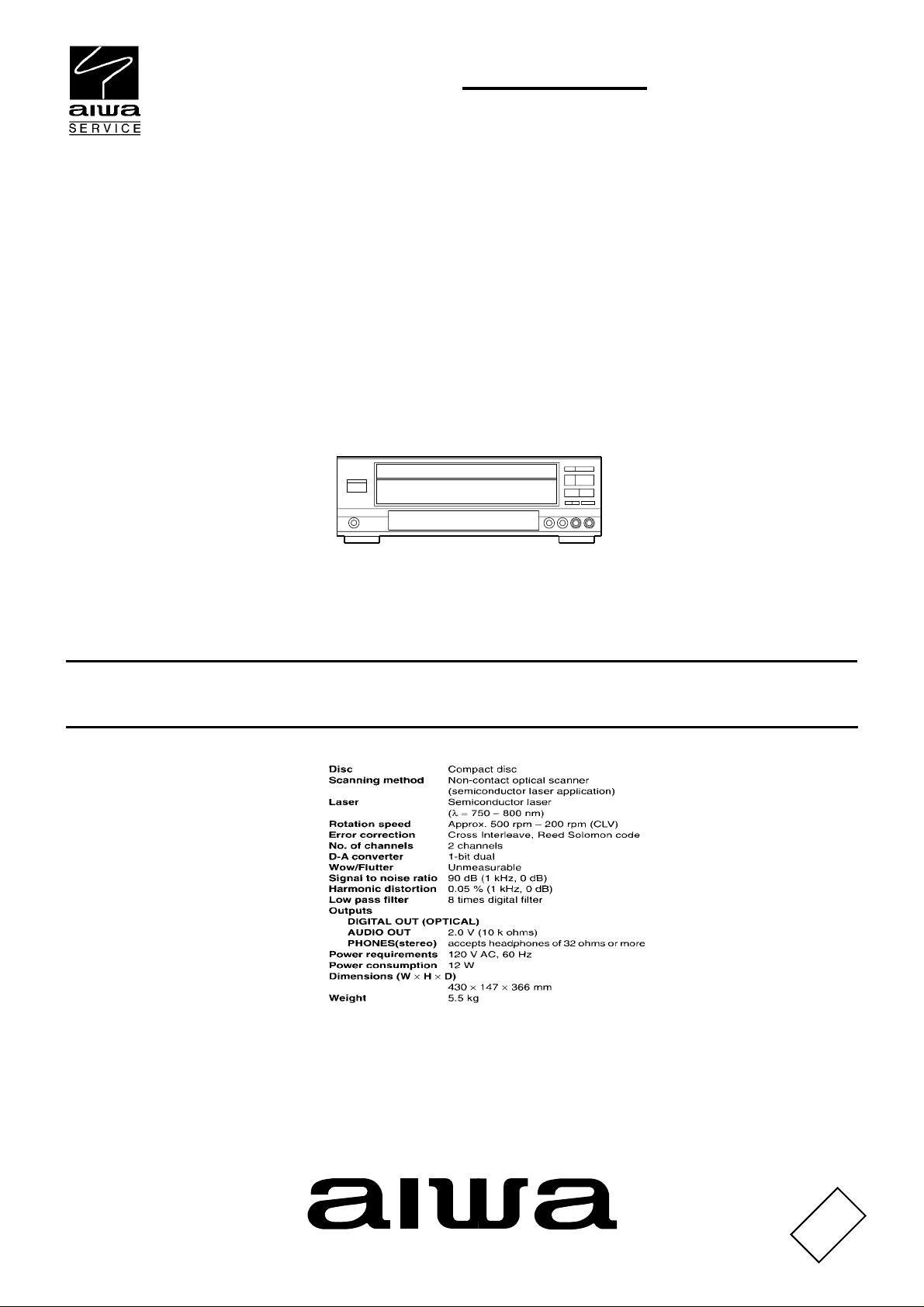
COMPACT DISC PLAYER
SPECIFICATIONS
Design and specifications are subject to change without
•
This Service Manual contains information about the the difference between
XC-30M (TYPE:U). If requiring the other information, see Service Manual
of the XC-30M (TYPE:U), S/M Code No.09-986-270-0O1.
notice
.
BASIC CD MECHANISM : 6ZG-1 S3DSH
If requiring information about the CD mechanism, see Service Manual of 6ZG-1,
S/M Code No.09-984-249-90T.
S/M Code No. 09-993-325-5O1
DATA
Page 2
PROTECTION OF EYES FROM LASER BEAM DURING SERVICING
This set employs laser. Therefore, be sure to follow carefully the
instructions below when servicing.
WARNING!
WHEN SERVICING, DO NOT APPROACH THE LASER EXIT
WITH THE EYE TOO CLOSELY. IN CASE IT IS NECESSARY TO
CONFIRM LASER BEAM EMISSION. BE SURE TO OBSERVE
FROM A DISTANCE OF MORE THAN 30cm FROM THE
SURFACE OF THE OBJECTIVE LENS ON THE OPTICAL
PICK-UP BLOCK.
Caution: Invisible laser radiation when
open and interlocks defeated avoid exposure to beam.
Advarsel:Usynling laserståling ved åbning,
når sikkerhedsafbrydere er ude af funktion.
Undgå udsættelse for stråling.
VAROITUS!
Laiteen Käyttäminen muulla kuin tässä käyttöohjeessa mainitulla tavalla saattaa altistaa käyt-täjän turvallisuusluokan 1 ylittävälle näkymättömälle lasersäteilylle.
VARNING!
Om apparaten används på annat sätt än vad som specificeras i
denna bruksanvising, kan användaren utsättas för osynling
laserstrålning, som överskrider gränsen för laserklass 1.
CAUTION
Use of controls or adjustments or performance of procedures
other than those specified herein may result in hazardous
radiation exposure.
ATTENTION
L'utilisation de commandes, réglages ou procédures autres que
ceux spécifiés peut entraîner une dangereuse exposition aux
radiations.
ADVARSEL!
Usynlig laserståling ved åbning, når sikkerhedsafbrydereer ude
af funktion. Undgå udsættelse for stråling.
This Compact Disc player is classified as a CLASS 1 LASER
product.
The CLASS 1 LASER PRODUCT label is located on the rear
exterior.
CLASS 1
KLASSE 1
LUOKAN 1
KLASS 1
LASER PRODUCT
LASER PRODUKT
LASER LAITE
LASER APPARAT
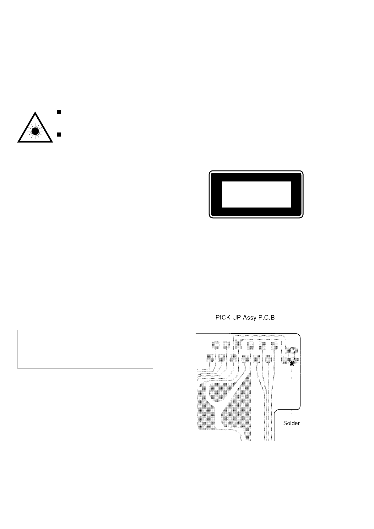
Precaution to replace Optical block
(KSS-213B)
Body or clothes electrostatic potential could ruin
laser diode in the optical block. Be sure ground
body and workbench, and use care the clothes
do not touch the diode.
1) After the connection, remove solder shown in
the right figure.
2
Page 3
ELECTRICAL MAIN PARTS LIST
REF. NO PART NO. KANRI DESCRIPTION
NO.
IC
87-AMB-613-010 C-IC,LC866440W-5J10
87-NF8-614-010 IC,SPS-442-1-W
87-020-903-010 IC,NJM7805FA
87-017-878-080 IC,TDA1308T
TRANSISTOR
87-026-235-080 CHIP-TR,DTC114EK
89-327-125-080 CHIP TR,2SC2712GR
89-213-702-010 TR,2SB1370E
89-111-625-080 TR,2SA1162
87-026-608-080 C-TR,DTC 123 JK
89-213-302-080 TR,2SB1330
DIODE
87-020-465-080 DIODE,1SS133 (110MA)
87-A40-184-090 DIODE,RF34
87-001-574-080 DIODE,1SR139-200 (1A)
87-017-083-080 ZENER,HZS4C2
FRONT C.B
C201 87-010-263-080 CAP, ELECT 100-10V
C202 87-010-196-080 CHIP CAPACITOR,0.1-25
C203 87-010-196-080 CHIP CAPACITOR,0.1-25
C204 87-010-553-040 CAP,E 47-16 GAS
C205 87-010-553-040 CAP,E 47-16 GAS
C206 87-010-197-080 CAP, CHIP 0.01 DM
C207 87-012-140-080 CAP 470P
C208 87-010-494-040 CAP,E 1-50 GAS
C209 87-010-496-040 CAP,E 3.3-50 GAS
CON201 87-099-200-010 CONN,7P 6216H
CON202 87-099-033-010 16P 6216 H
FC1 88-916-241-210 FF-CABLE, 16P 1.25 240MM
FC2 88-907-251-210 FF-CABLE, 7P 1.25 250MM R
FL501 86-VMB-601-010 FL,25U48101TA
L201 87-003-102-080 COIL, 10UH
LED501 87-017-785-080 LED,SEL4214S
LED502 87-017-785-080 LED,SEL4214S
LED503 87-017-785-080 LED,SEL4214S
LED504 87-017-785-080 LED,SEL4214S
LED505 87-017-785-080 LED,SEL4214S
LED506 87-A40-380-080 LED,SEL6510C-TP5 GRN
LED507 87-A40-380-080 LED,SEL6510C-TP5 GRN
LED508 87-A40-380-080 LED,SEL6510C-TP5 GRN
LED509 87-A40-467-080 LED,SEL6910A-TP5 ORN
LED510 87-A40-380-080 LED,SEL6510C-TP5 GRN
R541 87-022-355-080 C-RES,S10K-1/10W F
R542 87-022-355-080 C-RES,S10K-1/10W F
R543 87-022-355-080 C-RES,S10K-1/10W F
SW512 87-A90-095-080 SW,TACT EVQ11G04M
SW513 87-A90-095-080 SW,TACT EVQ11G04M
SW514 87-A90-095-080 SW,TACT EVQ11G04M
SW515 87-A90-095-080 SW,TACT EVQ11G04M
SW516 87-A90-095-080 SW,TACT EVQ11G04M
SW517 87-A90-095-080 SW,TACT EVQ11G04M
SW518 87-A90-095-080 SW,TACT EVQ11G04M
SW519 87-A90-095-080 SW,TACT EVQ11G04M
SW520 87-A90-095-080 SW,TACT EVQ11G04M
SW521 87-A90-095-080 SW,TACT EVQ11G04M
SW522 87-A90-095-080 SW,TACT EVQ11G04M
SW523 87-A90-095-080 SW,TACT EVQ11G04M
SW524 87-A90-095-080 SW,TACT EVQ11G04M
SW525 87-A90-095-080 SW,TACT EVQ11G04M
SW526 87-A90-095-080 SW,TACT EVQ11G04M
SW527 87-A90-095-080 SW,TACT EVQ11G04M
SW528 87-A90-095-080 SW,TACT EVQ11G04M
REF. NO PART NO. KANRI DESCRIPTION
X201 87-030-345-080 VIB,CER CST 5.76MGW
P-SW C.B
C401 87-010-178-080 CHIP CAP 1000P
C402 87-010-178-080 CHIP CAP 1000P
C403 87-010-503-040 CAP,E 220-4 GAS
C404 87-010-503-040 CAP,E 220-4 GAS
C406 87-010-549-040 CAP,E 47-6.3 GAS
C407 87-010-197-080 CAP, CHIP 0.01 DM
C408 87-010-549-040 CAP,E 47-6.3 GAS
C409 87-010-178-080 CHIP CAP 1000P
C410 87-010-178-080 CHIP CAP 1000P
C412 87-010-196-080 CHIP CAPACITOR,0.1-25
C415 87-010-805-080 C-CAP,S 1-16
C416 87-010-805-080 C-CAP,S 1-16
CON401 87-AM1-632-010 CONN ASSY,7P HP
CON503 87-009-345-010 CONN,2P PH H
CON505 87-009-346-010 CONN,3P PH H
J401 87-099-580-010 JACK,6.3 ST/SW/4609G
SW500 87-036-215-080 TACT SWITCH,EVQ-21404M
10KEY C.B
SW501 87-036-215-080 TACT SWITCH,EVQ-21404M
SW502 87-036-215-080 TACT SWITCH,EVQ-21404M
SW503 87-036-215-080 TACT SWITCH,EVQ-21404M
SW504 87-036-215-080 TACT SWITCH,EVQ-21404M
SW505 87-036-215-080 TACT SWITCH,EVQ-21404M
SW506 87-036-215-080 TACT SWITCH,EVQ-21404M
SW507 87-036-215-080 TACT SWITCH,EVQ-21404M
SW508 87-036-215-080 TACT SWITCH,EVQ-21404M
SW509 87-036-215-080 TACT SWITCH,EVQ-21404M
SW510 87-036-215-080 TACT SWITCH,EVQ-21404M
SW511 87-036-215-080 TACT SWITCH,EVQ-21404M
P-JACK C.B
J401 87-009-610-010 JACK PIN 2P H EARH
POW C.B
!
82-304-743-010 TERMINAL, 1P
C301 87-010-878-090 CAP,E6800-16
C302 87-010-196-080 CHIP CAPACITOR,0.1-25
C303 87-010-196-080 CHIP CAPACITOR,0.1-25
C304 87-010-805-080 C-CAP,S 1-16
C305 87-010-322-080 CHIP CAP 100P-50 CH
C306 87-010-236-080 CAP,E 1000-10 SME
C307 87-010-196-080 CHIP CAPACITOR,0.1-25
C308 87-010-196-080 CHIP CAPACITOR,0.1-25
C309 87-010-263-080 CAP, ELECT 100-10V
C310 87-010-197-080 CAP, CHIP 0.01 DM
C311 87-010-805-080 C-CAP,S 1-16
C321 87-010-247-080 CAP, ELECT 100-50V
C322 87-010-178-080 CHIP CAP 1000P
C323 87-010-247-080 CAP, ELECT 100-50V
C324 87-010-263-080 CAP, ELECT 100-10V
C325 87-010-405-080 CAP, ELECT 10-50V
C326 87-010-405-080 CAP, ELECT 10-50V
CON301 87-099-200-010 CONN,7P 6216H
CON303 87-099-199-010 CONN,6P 6216 H
!
F301 87-A90-426-080 FUSE,3A 125V 251
!
F302 87-A90-410-080 FUSE,0.5A 125V 251
FC3 88-906-351-110 FF-CABLE, 6P 1.25
!
PT301 87-AMB-607-010 PT,7AM-B U
NO.
• Regarding connectors, they are not stocked as they are not the initial order items.
The connectors are available after they are supplied from connector manufacturers upon the order is received.
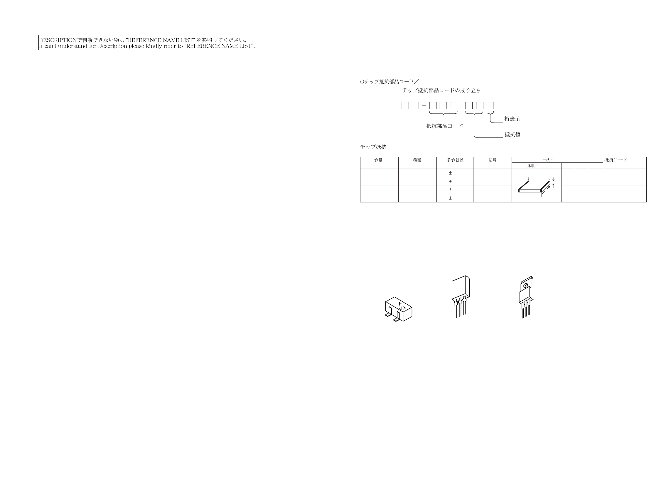
CHIP RESISTOR PART CODE
Chip Resistor Part Coding
88
A
Resistor Code
Chip resistor
Wattage Type Tolerance
1/16W 1005 5% CJ
1/16W
1/10W
1/8W
1608
2125
3216
5%
5%
5%
TRANSISTOR ILLUSTRATION
C
B
E
2SA1162
ECB
2SB1330
2SC2712
DTC114EK
DTC123JK
Symbol
Figure
Value of resistor
CJ
CJ
CJ
BCE
2SB1370
Form
L
W
Dimensions (mm)
LW t
1.0 0.5 0.35 104
t
1.6 0.8 0.45
2 1.25 0.45
1.6
0.55
3.2
Resistor Code
108
118
128
: A
: A
43
Page 4

BLOCK DIAGRAM
5J10
AC120V/60Hz
65
Page 5

SCHEMATIC DIAGRAM-1
IC201
LC866440W-5J10
87
Page 6

SCHEMATIC DIAGRAM-2
109
Page 7

IC DESCRIPTION
IC, LC866448W-5J10
Pin No. Pin Name I/O Description
1
2
3
4
5
6
7
8, 9
10
11
12
13
14
15
16
17
18
19
20
21
22
23
DISH.R
DISH.F
O-LED BS
O-CDON
NC
O-LED FS
_____________
RESET
VDD
VSS1
XTAL
EXTAL
VDD1
NC
I-KEY1
I-KEY2
I-CDSW
I-DISH.S
NC
I-KEY3
NC
I-PAL/PAL60
NC
—
—
—
—
—
—
—
—
—
—
O
CD turntable reverse control.
O
CD turntable forward control.
O
PREVIOUS key signal output.
O
CD system ON/OFF switch.
Not used.
O
NEXT key signal output.
I
Reset input.
5V power supply.
GND.
5.76MHz oscillator circuit.
5V power supply.
Not used.
I
Key matrix input.
I
I
CD switch signal input. (Pick up mecha of up & down and dish of open & close sw)
I
CD turntable sensor signal input. (Turntable no. and ON or no CD)
Not used.
I
Key matrix input.
Not used.
I
Video mode (NORMAL PAL, PAL60) control input.
Not used.
Pin No. Pin Name I/O Description
77
78
79
80
NC
I/O-BUSY
O-CLK
________________
O-AMUT
—
I/O
O
O
Not used.
Communication busy signal between system control µ-com and MPEG µ-com.
Serial clock signal to MPEG µ-com.
Audio mute control output.
IC BLOCK DIAGRAM
IC, TDA1308T
24
25-31
32-40
41
42
43-60
61
62
63, 64
65
66
67-69
70
71
72
73
74
75
I-RMOT
G1-G7
P1-P9
VDD2
VP
P10-P27
NC
NC
O-LED5, O-LED4
O-OPEN
O-CLOSE
O-LED3-O-LED1
O-LED PLY
O-LED PAU
O-LED CD
VSS2
K-DATA
K-STB
—
—
—
—
—
I
Remote control signal input.
O
FL GRID output G1-G7.
O
FL SEGMENT output P1-P9.
5V power supply input.
Power supply input for FL display.
O
FL SEGMENT output P10-P27.
Not used.
Not used.
O
LED control output for disc direct key 5 and 4.
O
CD tray open control output.
O
CD tray close control output.
O
LED control output for disc direct key 3, 2, 1.
O
PLAY key LED control output.
O
PAUSE key LED control output.
O
Dish LED control output.
GND.
O
Serial data signal for KARAOKE IC.
O
Serial strobe signal for KARAOKE IC.
76
K-CLK
O
Serial clock signal for KARAOKE IC.
1211
Page 8

MECHANICAL EXPLODED VIEW 1/1
17
F
C
1
F
F
B
HLDR,CABI
P.C.B
C
3
4
C
5
C
B
6
A
I
15
F
10
E
P.C.B
8
GUIDE,FL
FL501
C
HLDR,SUB
C
12
11
13
P.C.B
C
P.C.B
B
C
19
C
HLDR,IC
A
22
6ZG-1
S3DSHNM
A
HLDR,PCB
A
A
18
C
C
P.C.B
23
G
H
HLDR,PT
14
21
B
D
D
2
C
B
9
7
A
16
CHASSIS,MAIN
A
A
16
A
1413
20
Page 9

MECHANICAL PARTS LIST 1/1
REF. NO PART NO. KANRI DESCRIPTION
NO.
1 87-AM1-003-010 CABI,STEEL
2 87-AMB-004-010 WINDOW,DISPLAY(U)
3 8Z-AM1-003-010 PANEL,TRAY (35)
4 82-NE6-067-010 BADGE,AIWA 30N
5 8Z-AM1-002-010 PANEL,FR (35)
6 87-AMB-001-010 CABI,FR U
7 87-AM1-008-010 KEY,PBC
8 87-AMB-006-010 KEY,DIRECT(U)
9 87-AMB-005-010 KEY,DISPLAY(U)
10 8Z-AM1-004-010 KEY,TEN(35)
11 87-AM1-015-010 REFLECTOR,FF
12 87-AM1-014-010 REFLECTOR,PLAY
13 87-AM1-203-010 GUIDE,LED
14 87-AM1-007-010 KEY,PLAY
15 87-AM1-009-010 KEY,POWER
16 82-AA1-029-110 FOOT (SG)
17 87-MAT-009-010 WINDOW,TOP(U)
18 8Z-AM1-011-010 PANEL,REAR(R) 35 UBN
19 8Z-AM1-010-010 PANEL,REAR(L) 35 UBN
20 87-085-185-010 BUSHING, CORD (E)
REF. NO PART NO. KANRI DESCRIPTION
!
21 87-A80-110-010 AC CORD ASSY,U-SPT-2W
22 84-ZG1-245-210 CAP,OPTICAL
!
23 87-AMB-607-010 PT,7AM-B U
A 87-067-584-010 TAPPING SCREW, BVT2+3-6
B 87-591-094-410 TAPPING SCREW, QIT+3-6
C 87-067-703-010 TAPPING SCREW, BVT2+3-10
D 87-B10-021-010 BVT2+3-8W/CONVEX BLK
E 81-MK1-210-010 S-SCREW,VFT2+3-16
F 87-067-641-010 UTT2+3-8(W/O SLOT)BL
G 87-067-585-010 TAPPING SCREW, BVTT+4-6
H 87-067-579-010 TAPPING SCREW, BVT2+3-8
NO.
COLOR NAME TABLE
Basic color symbol Color Basic color symbol Color Basic color symbol Color
B Black C Cream D Orange
G Green H Gray L Blue
LT Transparent Blue N Gold P Pink
R Red S Silver ST Titan Silver
T Brown V Violet W White
WT Transparent White Y Yellow YT Transparent Yellow
LM Metallic Blue LL Light Blue GT Transparent Green
LD Dark Blue DT Transparent Orange
ACCESSORIES/PACKAGE LIST
REF. NO PART NO. KANRI DESCRIPTION
NO.
1 8Z-AM1-903-010 IB,U(ESF)N
2 87-A80-032-010 CORD,PIN 2P RED-WHT
3 87-AMB-701-010 RC UNIT,7AC04
15
Page 10

2–1 1, IKENOHATA 1–CHOME, TAIT O-KU, TOKYO 110, JAP AN TEL:03 (3827) 3111
727105
Printed in Singapore
 Loading...