

Page 1

OPERATING INSTRUCTIONS
MANUAL DE INSTRUCCIONES
MODE D’EMPLOI
CT-FX531M YU
STEREO CAR CASSETTE RECEIVER
RADIO-CASSETTE ESTEREOFONICO PARA AUTOMOVIL
ENGLISH
ESPAÑOL
FRANÇAIS
OWNER’S RECORD
For your convenience, record the model number and
serial number (you will find them on the bottom side of
your set) in the space provided below. Please refer to
them when you contact your AIWA dealer in case of
difficulty.
Model No. CT-FX531M
Serial No.
8B-KT9-901-01
001006ATM-OX
Page 2
d
INSTALLATION AND CONNECTIONS
INSTALACION Y CONEXIONES
INSTALLATION ET CONNEXIONS
INSTALAÇÕES E LIGAGÕES
ENGLISH
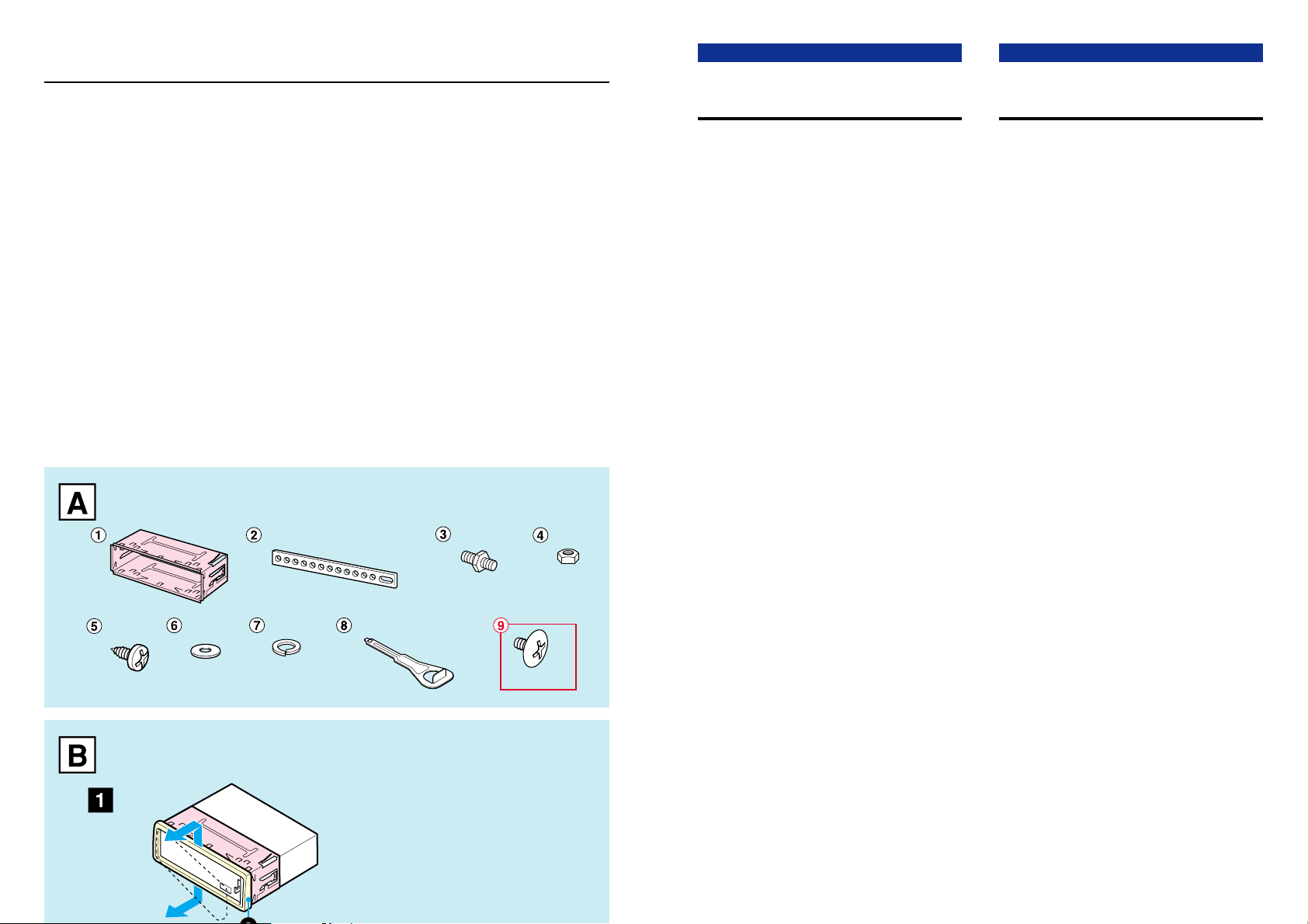
SUPPLIED MOUNTING HARDWARE FOR
INSTALLATION → A
INSTALLATIONS
The installation scenario described in this manual
assumes that you have a typical car. If your specific car
requires any adjustments or modifications, consult your
nearest AIWA car audio dealer.
FRANÇAIS
MATERIEL DE MONTAGE FOURNI POUR
L’INSTALLATION → A
INSTALLATION
Le scénario d’installation indiqué dans ce manuel
présuppose une voiture typique. Si votre voiture exige un
ajustement ou une modification, consultez le revendeur
de chaîne audio automobile AIWA le plus proche.
YU/YL
A
× 2
× 2
8B-KT9-902-01
001006ATM-OX
Printed in Indonesia
× 2
× 5
PRECAUTIONS
• This unit is designed for negative-ground, 12-V DC
operation only.
• Before starting installation, make sure the ignition switch
is set to OFF and disconnect the ground terminal of the
car battery to avoid short-circuiting.
• Install the unit where it will not hamper the operation of
the vehicle.
• Install the unit where it will not injure the passenger if
there is a sudden stop, like an emergency stop.
• Avoid installing the unit where it would be subject to high
temperatures caused by direct sunlight or hot air from
the heater, or where it would be subject to dust, dirt or
excessive vibration.
• Use only the supplied mounting hardware, for a safe
and secure installation.
PREINSTALLATIONS → B
If there is installation hardware for another receiver
already in the dashboard, it must be removed.
Remove the trim plate from the unit → 1
Remove the trim plate a by pushing the upper and lower
parts of the plate in the direction of the arrow.
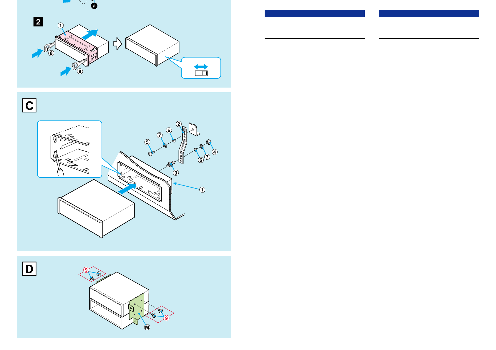
Remove the installation sleeve → 2
Insert the levers 8 along each groove on both sides of
the unit to unlock the installation sleeve 1 and pull the
sleeve to detach it from the unit.
9k/10k switch (located on the bottom of the unit)
See the section “SPECIFICATIONS” of the separate
Operating Instructions (set to 10k at the factory).
BASIC INSTALLATIONS → C
Installation in the dashboard
Note that the Installation shown is a typical example.
For some car types you may need to make adjustments
or modifications to install the unit. If your car is of such
type, consult your nearest AIWA car audio dealer.
Mounting-angle adjustment
The mounting angle should be 30 degrees or less from
horizontal.
Caution on installation without using the
sleeve → D
Be sure to use the supplied screws 9 shown
in A to attach the mounting brackets M (not
supplied).
PRECAUTION
•
Cet appareil est conçu uniquement pour le fonctionnement
sur courant continu 12 V, masse négative.
• Avant de commencer l’installation, vérifiez que le
commutateur d’allumage est réglé à OFF et déconnectez
le prise de masse de la batterie auto pour éviter tout
court-circuit.
• Installez l’appareil à un endroit où il ne gênera pas le
fonctionnement de la voiture.
• Installez l’appareil à un endroit où il ne blessera pas le
passager, en cas d’arrêt brutal, par exemple un arrêt
d’urgence.
Evitez d’installer l’appareil à un endroit en plein soleil ou
•
sous l’air chaud du chauffage, où il sera soumis à des
températures élevées, ou bien à un endroit où il sera
soumis à une poussière, de la saleté ou de fortes vibrations.
• Utilisez seulement le matériel de montage fourni pour
assurer une installation sûre et solide.
PREPARATIFS POUR L’INSTALLATION
S’il y a déjà du matériel de montage pour un autre
récepteur dans le tableau de bord, il doit être retiré.
Retirez la plaque d’ajustement de l’appareil → 1
Retirez la plaque d’ajustement a en poussant les parties
haut et bas de la plaque dans le sens de la flèche.
Retirez le manchon d’installation → 2
Insérez les leviers 8 le long de chaque cannelure sur les
deux côtés de l’appareil pour débloquer le manchon
d’installation 1, puis tirez sur le manchon pour le détacher
de l’appareil.
Commutateur 9k/10k (situé sur le dessous de
l’appareil)
Voir la section “SPECIFICATIONS” du mode d’emploi
séparé (réglé à 10k à l’usine).
→ B
INSTALLATION DE BASE → C
Installation dans le tableau de bord
Pour certains types de voiture, il faudra peut-être faire
des ajustements ou modifications pour installer l’appareil.
Si c’est le cas pour votre voiture, consultez le revendeur
de chaînes audio automobiles AIWA le plus proche.
Ajustement de l’angle de montage
L’angle de montage doit être de 30˚ ou moins de
l’horizontale.
Précaution pour l’installation sans manchon
→ D
Utilisez les vis fournies 9 indiquées dans A pour
attacher les fixations de montage M (non fournies).
Page 3
ESPAÑOL
PORTUGUÊS
1
9k 10k
23
M5 × 6 mm
M5 × 6 mm
ACCESORIOS DE MONTAJE SUMINISTRADOS
PARA LA INSTALACION
→ A
INSTALACION
La instalación descrita a lo largo de este manual presupone
que tiene un coche normal. Si su coche requiere ajustes
o modificaciones, consulte con su concesionario de audio
para coches de AIWA más cercano.
PRECAUCIONES
• Este aparato fue diseñado para una conexión a tierra
negativa y funciona con una CC de 12 V.
• Antes de empezar la instalación, compruebe que el
interruptor de encendido está en OFF y desconecte el
terminal a tierra de la batería de coche para evitar que
se produzca un cortocircuito.
• Instale el aparato donde no moleste el funcionamiento
del vehículo.
• Instale el aparato en un lugar donde no provoque
heridas a los pasajeros por un frenado repentino, como
en el caso de un frenado de emergencia.
• Evite instalar el aparato donde quede expuesto a altas
temperaturas provocadas por los rayos directos del sol
o el aire caliente de la calefacción o donde pueda estar
expuesto al polvo, suciedad o vibraciones excesivas.
• Utilice sólo los accesorios de montaje suministrados,
para una instalación firme y segura.
INSTALACION PREVIA → B
Si ya se han instalado accesorios para instalación de otro
aparato en el tablero, deberá desmontarlos.
Desmonte la placa de adorno del aparato → 1
Desmonte la placa de adorno a empujando las partes
superior e inferior de la placa en el sentido de la flecha.
Desmonte el manguito de instalación → 2
Inserte las palancas 8 a lo largo de cada ranura en ambos
lados del aparato para destrabar el manguito de instalación
1
y tire del manguito para desmontarlo de la del aparato.
Interruptor de 9k/10k (en la parte inferior del aparato)
Consulte la sección “ESPECIFICACIONES” del manual
de instrucciones que se entrega por separado (ajuste a
10k en la fábrica).
INSTALACION BASICA → C
Instalación en el tablero
Tenga en cuenta que la instalación que se describe es a
modo de ejemplo. Para algunos modelos de coche, puede
ser necesario hacer ajustes o modificaciones para instalar
el aparato. Si su coche es de este tipo, consulte con su
concesionario de audio para coches de AIWA más cercano.
Ajuste del ángulo de montaje
El ángulo de montaje debe ser de 30 grados o menos de
la horizontal.
Precauciones sobre la instalación sin
utilizar el manguito → D
Se deben utilizar siempre los tornillos
suministrados 9 que aparecen en A, para instalar
las ménsulas de montaje M (no suministradas).
COMPONENTES DE MONTAGEM FORNECIDOS
PARA INSTALAÇÃO
→ A
INSTALAÇÃO
A instalação da forma como é descrita neste manual aplicase aos veículos mais comuns. Se seu veículo exigir
particularmente quaisquer ajustes ou modificações, consulte
o revendedor de som automotivo AIWA de sua região.
PRECAUÇÕES
• Este aparelho foi projetado para funcionar somente em
corrente contínua de 12 volts com terra negativo.
Antes da instalação, certifique-se de que a chave de
•
ignição do veículo esteja desligada e desconecte o borne
de terra da bateria do veículo para evitar curto-circuito.
• Instale a unidade em lugar onde ela não venha a
prejudicar a condução do veículo.
• Instale o aparelho em lugar onde o mesmo não venha
a representar risco de ferimento dos passageiros em
caso de parada repentina, como por exemplo numa
freada de emergência.
Evite instalar o aparelho em lugar onde o mesmo fique
•
exposto a luz solar direta ou a ar quente gerado por
aquecedor. Evite também locais onde o aparelho fique
exposto a poeira, sujeira ou vibração excessiva.
• Utilize somente os componentes de montagem
fornecidos para assegurar uma instalação segura e
confiável.
PRÉ-INSTALAÇÃO → B
Se já houver ferragem de instalação para outro receptor
no painel de instrumentos, ela deverá ser removida.
Remoção da moldura da unidade → 1
Remova a moldura a, pressionando as partes superior
e inferior da moldura na direção da seta.
Remoção da luva de instalação → 2
Introduza as alavancas 8 ao longo de cada ranhura nos
dois lados da unidade para destravar a luva de instalação
e puxe a luva para separá-la da unidade.
Chave 9k/10k (localizada na base da unidade)
Veja a seção “ESPECIFICAÇÕES” nas instruções de
uso independentes (ajustada a 10k na fábrica).
INSTALAÇÃO BÁSICA → C
Instalação no painel de instrumentos
Note que a instalação aqui mostrada é a mais comum.
Para alguns tipos de veículos, talvez seja necessário
fazer ajustes ou modificações para instalar a unidade. Se
seu carro for de um destes tipos, consulte o revendedor de
som automotivo AIWA de sua região.
Ajuste do ângulo de montagem
O ângulo de montagem deve ser de 30 graus ou menos
em relação à base horizontal.
Precaução sobre a instalação sem o uso
da luva → D
Certifique-se de usar os parafusos fornecidos 9
que aparecem em A para fixar os suportes de
montagem M (não fornecidos).
1
Page 4
ENGLISH
FRANÇAIS
E
F
A
B C
15A
CONNECTIONS
PRECAUTIONS
Precaution on making connections
Before connecting, make sure that the ignition switch is
set to OFF, and remove the ground terminal of the battery
to protect the unit and your car from damage.
Caution
Make the connections correctly, as illustrated in the
connection diagram.
Do not connect the negative ( cord of each speaker wire
to a common point. When replacing the fuse, be sure to
use a fuse of the same rated amperage. Use of a fuse of
a higher rating may cause serious damage to the unit.
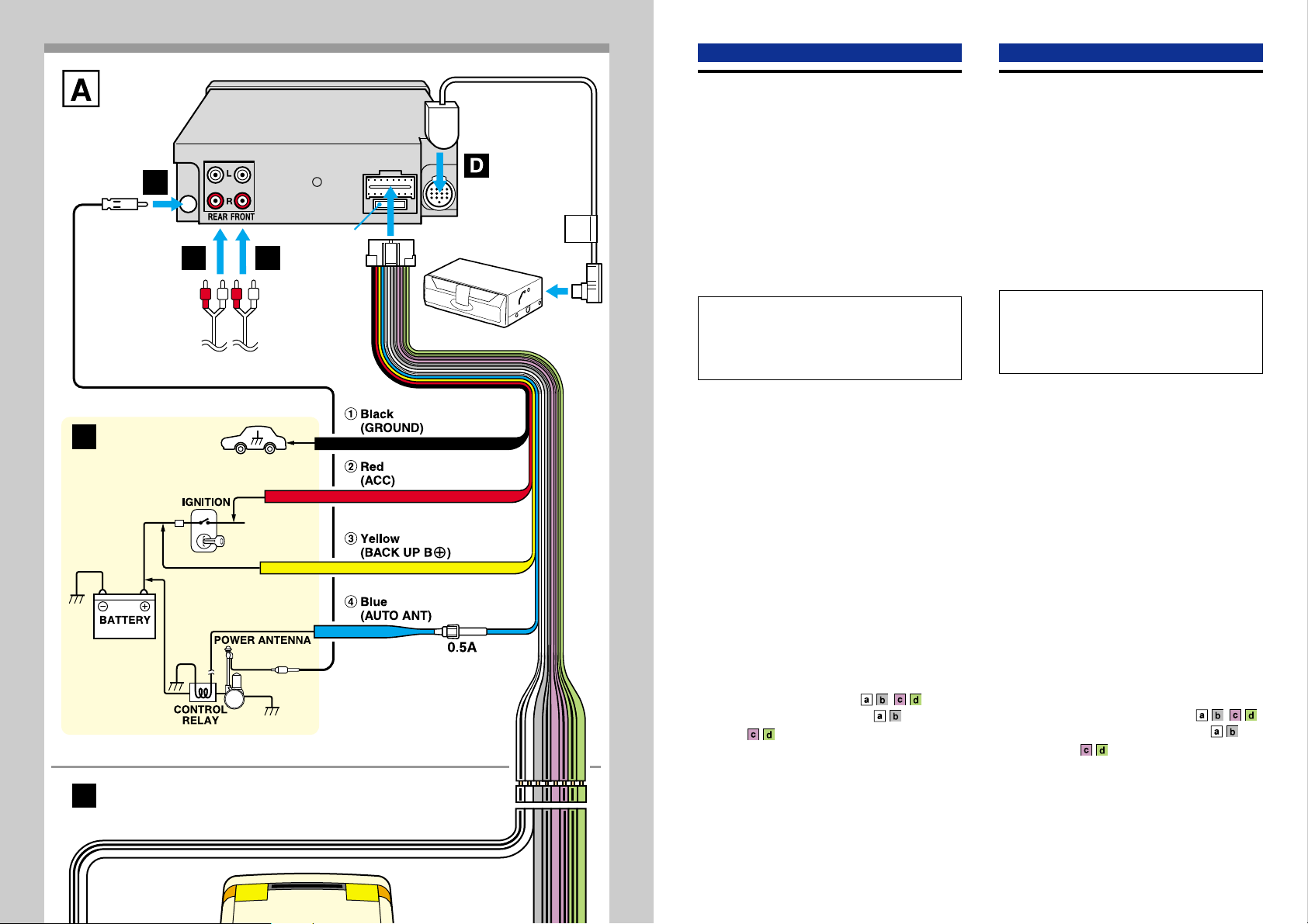
CONNECTION DIAGRAM → A
One or more of the connectors B, C, and D may not
exist on the model you purchased. Make the
appropriate connection or connections according to
the configuration of your unit.
See the section “SPECIFICATIONS” of the separate
Operating Instructions.
A From the car antenna
B To the input jack of the optional power
amplifier (for the rear channel)
C To the input jack of the optional power
amplifier (for the front channel)
D
From the optional AIWA compact disc changer
E To the wiring of the vehicle
Colors of leads
1 Black (ground lead to be connected to vehicle [metal]
body.)
2 Red (ACC lead to be connected to the terminal from
which power is supplied when the ignition switch is
set to ACC.)
3 Yellow (battery lead to be connected to the backup
terminal from which power is always supplied.)
4 Blue (power antenna lead to be connected to the
terminal of the control relay switch for a vehicle
equipped with a fully automatic power antenna. This
lead is not used for a vehicle with a manual antenna
or a switch-operated power antenna. If you will use
the optional power amplifier with the unit, connect this
lead to the remote terminal of the amplifier.)
F Speaker connections
4-SPEAKER CONNECTIONS
2-SPEAKER CONNECTIONS →
Note →
Insulate the end of the unused lead with a piece of tape.
Notes
• Use speakers with an impedance of 4 to 8 ohms and
with adequate power-handling capacities. Otherwise,
the speakers may be damaged.
• Do NOT connect the speakers in parallel.
• Do NOT connect the terminals of the speaker system to
the car chassis.
→
CONNEXIONS
PRECAUTIONS
Précautions pour les connexions
Avant le raccordement, vérifiez que la clé d’allumage est
sur OFF, et débranchez le prise de masse de la batterie
pour protéger l’appareil et votre voiture des dommages.
Attention
Effectuez les connexions correctement, comme indiqué
sur le diagramme de connexion.
Ne raccordez pas le cordon négatif ( de chaque fil de
haut-parleur à un point commun. Au remplacement du
fusible, utilisez un fusible à ampérage nominal identique.
L’emploi d’un fusible à ampérage plus élevé peut
sérieusement endommager l’appareil.
DIAGRAMME DE CONNEXION → A
Un ou plusieurs des connecteurs B, C, et D peuvent
ne pas exister sur le modèle que vous avez acheté.
Effectuez la ou les connexions adaptées
conformément à la configuration de votre appareil.
Consultez la section “SPECIFICATIONS” du mode
d’emploi séparé.
A De l’antenne du véhicule
B A la prise d’entrée de l’amplificateur de
puissance en option (pour le canal arrière)
C A la prise d’entrée de l’amplificateur de
puissance en option (pour le canal avant)
D
Du changeur de disque compact AIWA en option
E
Vers le
Couleurs des fils
1 Noir (fil de mise à la terre à raccorder à la carrosserie
2 Rouge (fil ACC à raccorder à la prise à partir de
3 Jaune (fil de batterie à raccorder à la prise de secours
4 Bleu (fil d’antenne électrique à raccorder à la prise du
F Raccordement des enceintes
RACCORDEMENT A 4 ENCEINTES
RACCORDEMENT A 2 ENCEINTES →
Remarque →
Remarques
• Utilisez des enceintes à impédance de 4 à 8 ohms et
puissance nominale adéquate. Sinon elles seront
endommagées.
• Ne raccordez PAS les enceintes en parallèle.
• Ne raccordez PAS les prises du système d’enceintes
au châssis de la voiture.
câblage du véhicule
[métal] du véhicule.)
laquelle la puissance est fournie quand la clé
d’allumage est réglée sur ACC.)
de laquelle l’alimentation se fait toujours.)
commutateur de relais de commande pour un véhicule
équipé d’une antenne électrique entièrement
automatique. Ce fil n’est pas utilisé sur les véhicules
à antenne manuelle ou antenne électrique opérée
par commutateur. Si vous souhaitez utiliser
l’amplificateur de puissance en option avec cet
appareil, raccordez ce fil à la prise de télécommande
de l’amplificateur.)
→
Isoler l’extrémité du fil inutilisé avec du ruban.
Page 5

ESPAÑOL
PORTUGUÊS
CONEXIONES
PRECAUCIONES
Precauciones al hacer las conexiones
Antes de conectar, confirme que el interruptor de encendido
está en OFF y desmonte el terminal a tierra de la batería
para proteger el aparato y su coche contra daños.
Precaución
Haga las conexiones correctamente, tal como se describe
en el diagrama de conexiones.
No conecte el cable negativo ( de cada cable de altavoz a un
punto común. Cuando cambie el fusible, utilice siempre uno del
mismo amperaje nominal. El uso de un fusible de mayor
régimen puede provocar daños importantes en el aparato.
DIAGRAMA DE CONEXIONES → A
Pueden no existir uno o más de los conectores B, C
y D en el modelo comprado. Haga las conexiones
apropiadas de acuerdo con la forma de su aparato.
Consulte la sección “ESPECIFICACIONES” del
manual de instrucciones que se entrega por separado.
A De la antena del coche
B A la toma de entrada del amplificador de
potencia opcional (para el canal trasero)
C A la toma de entrada del amplificador de
potencia opcional (para el canal delantero)
D Del cambiador de discos compacto
opcional de AIWA
E Al cableado del vehículo
Colores de los cables
1 Negro (cable a tierra a conectar a la carrocería del
vehículo [metal].)
Rojo (cable ACC a conectar al terminal que recibe eléctrica
L
R
L
R
L
R
L
R
2
cuando el interruptor de encendido está en ACC.)
3 Amarillo (cable de batería a conectar al terminal de
reserva con un flujo permanente de electricidad.)
Azul (cable de antena motriz a conectar al terminal del
4
interruptor del relé de control para un vehículo equipado
con antena motriz totalmente automática. Este cable no
se debe utilizar en un vehículo con antena manual o
antena motriz que funcione mediante interruptor. Si
utiliza el amplificador de potencia opcional en esta unidad.
conecte este cable al terminal remoto del amplificador.)
F Conexiones de altavoces
CONEXIONES PARA 4 ALTAVOCES
→
CONEXIONES PARA 2 ALTAVOCES →
Nota →
Aísle la punta del conductor sin usar con cinta.
Notas
• Utilice altavoces con una impedancia de 4 a 8 ohmios
y con suficiente capacidad eléctrica. De lo contrario
puede dañar los altavoces.
• NO conecte los altavoces en paralelo.
• NO conecte los terminales del sistema de altavoces al
chasis del coche.
CONEXÕES
PRECAUÇÕES
Precauções ao efetuar conexões
Antes de efetuar as conexões, certifique-se de que a
chave de ignição esteja desligada e desconecte o borne
de terra da bateria para proteger a unidade e seu veículo
contra danos.
Atenção
Efetue adequadamente as conexões, como mostra o
diagrama de conexões.
Não conecte o fio negativo
em nenhum ponto comum. Ao trocar o fusível, certifique-se
de usar um fusível com a mesma amperagem nominal. A
utilização de um fusível com amperagem nominal maior
poderá causar sérios danos à unidade.
DIAGRAMA DE CONEXÕES → A
Um ou mais de um dos conectores B, C ou D pode
não existir no modelo adquirido. Faça a conexão ou
conexões apropriadas, de acordo com a configuração
de sua unidade.
Veja a seção “ESPECIFICAÇÕES” das instruções
de uso independentes.
A Da antena do veículo
B À entrada do amplificador de potência
opcional (para o canal traseiro)
c À entrada do amplificador de potência
opcional (para o canal frontal)
D Do CD changer opcional AIWA ADC-EX106,
ADC-M100
E À fiação do veículo
Cor dos fios
1 Preto (fio terra para conexão à carroceria de metal do
veículo.)
2 Vermelho (fio ACC para conexão ao terminal de
reserva que fornece eletricidade quando a chave de
ignição está na posição ACC.)
3 Amarelo (fio de bateria para conexão ao terminal de
reserva que fornece eletricidade permanentemente.)
4 Azul (fio de antena motorizada a ser conectado ao
terminal do comutador do relé de controle em veículos
equipados com antena motorizada completamente
automática. Este fio não é usado em veículos com
antena manual ou antena motorizada operada por
interruptor. Se utilizar o amplificador de potência
opcional com a unidade, conecte este fio ao terminal
de controle remoto do amplificador.)
F Conexões de alto-falantes
CONEXÕES DE 4 ALTO-FALANTES
CONEXÕES DE 2 ALTO-FALANTES →
Observação →
Aplique fita isolante à extremidade do fio não utilizado.
Observações
• Utilize alto-falantes com impedância de 4 a 8 ohms e
com potência utilizável adequada. Caso contrário, os
alto-falantes poderão sofrer danos.
• NÃO conecte os alto-falantes em paralelo.
• NÃO conecte os terminais do sistema de alto-falantes
ao chassi do veículo.
(
de cada um dos alto-falantes
→
Page 6

PRECAUTIONS
• Use only in a 12-volt DC negative-ground electrical
system.
• Disconnect the vehicle’s negative battery terminal
while mounting and connecting the unit.
• When replacing the fuse, be sure to use one with an
identical amperage rating. Using a fuse with a higher
amperage rating may cause serious damage to the
unit.
• Keep screwdrivers, etc. and other metallic or magnetic
objects away from the playback head.
• When your vehicle has been parked in direct sunlight
resulting in a considerable rise in the temperature
inside, allow the unit to cool off before operating it.
• Keep the volume at a level at which you can hear
outside warning sounds (horns, sirens, etc.).
NOTE
This equipment has been tested and found to comply
with the limits for a Class B digital device, pursuant to
Part 15 of the FCC Rules. These limits are designed to
provide reasonable protection against harmful
interference in a residential installation.
This equipment generates, uses, and can radiate radio
frequency energy and, if not installed and used in
accordance with the instructions, may cause harmful
interference to radio communications. However, there
is no guarantee that interference will not occur in a
particular installation. If this equipment does cause
harmful interference to radio or television reception,
which can be determined by turning the equipment off
and on, the user is encouraged to try to correct the
interference by one or more of the following measures:
— Reorient or relocate the receiving antenna.
— Increase the separation between the equipment
and receiver.
— Connect the equipment into an outlet on circuit
different from that to which the receiver is connected.
— Consult the dealer or an experienced radio/TV
technician for help.
CAUTION
Modifications or adjustments to this product, which are
not expressly approved by the manufacturer, may void
the user’s right or authority to operate this product.
TABLE OF CONTENTS
THEFT PROTECTION .............................................. 2
BASIC OPERATION, AUDIO AND CLOCK
ADJUSTMENT .....................................................2
RADIO OPERATION ................................................3
TAPE PLAYBACK..................................................... 5
AUXILIARY EQUIPMENT......................................... 6
OTHER FUNCTIONS ...............................................6
STEERING WHEEL REMOTE CONTROL............... 7
CD CHANGER OPERATION.................................... 7
TROUBLESHOOTING .............................................. 8
MAINTENANCE ........................................................ 9
SPECIFICATIONS .................................................... 9
Note
Some buttons are assigned two or more functions.
For detailed descriptions, refer to the related pages.
Notes on cassettes
Do NOT expose cassettes to direct sunlight, extremely
high or cold temperature or moisture.
Keep cassettes away from equipment with built-in
magnets to avoid unwanted noise or loss of sound
quality.
Do NOT touch the tape of a cassette, as any dirt or dust
will contaminate the heads.
Be sure to remove any cassette from the unit if you are
not using it.
DEMO (Demonstration) mode
The unit has an extra display mode, which demonstrates
the display of the operation modes of the unit. The unit
switches to DEMO mode automatically if you turn the
unit on and leave it as it is for 5 seconds after all the
connections have been completed.
To cancel DEMO mode
During DEMO mode, press and hold DISP for more than
2 seconds.
To resume DEMO mode, press and hold DISP again for
more than 2 seconds.
Caution on the transit protection pad
Be sure to remove the pad before operating the unit.
1
ENGLISH
1
ENGLISH
Transit protection pad
Page 7

THEFT PROTECTION
Take the front panel with you when leaving the car, and
keep it in the supplied carrying case.
Detaching the front panel
Before detaching the front panel, remove the cassette to
prevent possible damage to the unit.
1 Press z to remove the cassette.
2 Press and hold PWR/MUTE until the unit turns off.
3 Press %. (Hold the panel with one hand to prevent
accidentally dropping it.)
4 Remove the panel.
BASIC OPERATION,
AUDIO AND CLOCK
ADJUSTMENT
Smart Jog
Turning the unit on/off
• You can turn the unit on by pressing any button on the
front panel except %, z and the Smart Jog. The unit
also turns on when you insert a cassette.
• Press and hold PWR/MUTE until the unit turns off.
Attaching the front panel
1 Engage the left side of the front panel to the left catch
on the unit.
2 Push the panel forward until it locks. Be sure not to
press any buttons while you are attaching the panel.
Note
Do not touch the front panel connector. This could cause
a poor or faulty connection.
Security lamp
The security lamp will continue to flash while the front
panel is detached from the unit.
Note
Most operations described in this manual require
the unit to be turned on before starting the operation,
unless explicitly stated otherwise.
Changing the source mode
1 Press FNC.
Pressing FNC cycles through source modes in the
following order:
* Tape Play mode (available while a cassette is in the
player)
**CD Changer Play mode (available when an optional
CD Changer is connected)
Adjusting the volume
1 Turn the Smart Jog.
VOL (volume)
indication appears.
Muting the sound
1 Press PWR/MUTE briefly.
MT indicator flashes.
To restore volume, briefly press PWR/MUTE again.
ENGLISH
ENGLISH
ENGLISH
2
2
Page 8

Adjusting sound
You can select the following modes for adjusting sound
depending on the music you listen to: BASS (low
frequencies), TRE (high frequencies), BAL (left/right),
FAD (front/rear), H-BASS (high bass)*, and DSSA
(Drivers Sound Stage Adjustment)**
* You can reinforce the bass sound.
** You can adjust sound stage and tone balance to best
serve a particular seat in the car.
1 Press SEL repeatedly to select the mode to be
adjusted.
Pressing SEL cycles through the modes. The
selected mode’s indicator appears.
2 Turn the Smart Jog to increase or decrease the level
for the selected mode (except for H-BASS and
DSSA).
In H-BASS mode, turn the Smart Jog to select 1
(low), 2 (medium), 3 (high), or OFF.
In DSSA mode, turn the Smart Jog to select L (for the
front left seat), R (for the front right seat), or OFF.
Notes
• Adjust the level or select an item within 5 seconds, or
the selected mode will return to previous state.
• When DSSA is activated, you cannot adjust BAL, FAD,
BASS, and TRE.
Restoring the factory settings
1 Turn off the unit.
2 Press and hold DISP until “LEVEL --” appears in the
display.
Note
You can restore the factory settings only for VOL, BASS,
TRE, BAL, FAD, H-BASS, and DSSA and aligned
source volume levels.
Muting button beep sounds
1 Turn off the unit.
2 Press and hold SEL until “BEEP” appears in the
display.
3 Turn the Smart Jog to select ON or OFF.
4 Press SEL.
The unit turns off.
Setting the clock
1 Press and hold SEL until the clock indication flashes
in the display.
2 Press TUNEi (to set hour) or TUNEk (to set
minute) and turn the Smart Jog.
3 Press SEL.
Aligning the source levels
(Source Level Adjuster)
Volume may vary each time you change the source
mode. In this case, you can align each source mode’s
volume to almost the same level.
1 Press FNC repeatedly to select the desired mode.
2 Press DISP while pressing SEL.
“LEVEL 0” appears in the display.
3 Turn the Smart Jog to adjust the level.
Note
Adjust the level within 5 seconds, or the selected mode
will be canceled.
Displaying the clock
1 Press DISP.
To return to the former display, press DISP again.
RADIO OPERATION
Tuning in to a station
(Seek/Manual Tuning)
Stereo indicator
Band indicator* Frequency
indication
* “F” means FM, and “A” means AM.
Local indicator
3
ENGLISH
3
ENGLISH
Page 9

1 Press FNC repeatedly to select the desired band
(F1, F2, F3, A1 or A2).
2 Press TUNEi (to move to higher frequencies) or
TUNEk (to move to lower frequencies) to tune in to
a station.
“ST” appears in the display when an FM station is
broadcasting in stereo, and receiving conditions are
good.
Seek Tuning and Manual Tuning
• Press and hold TUNEi or TUNEk until Seek
Tuning starts.
The unit locates a station automatically (Seek
Tuning).
• Press TUNEi or TUNEk repeatedly to search for
a desired station while increasing or decreasing
the frequency step by step (Manual Tuning).
To stop Seek Tuning, press TUNEi or TUNEk
again.
Monaural mode
When FM signals become weak, or FM reception
becomes poor, the unit automatically switches to
Monaural mode to reduce noise.
Local mode
Local mode allows you to tune in only to strong stations
during Seek Tuning.
1 Press LO before you start Seek Tuning.
“LO” appears in the display.
To return to Distant mode, press LO again.
“LO” disappears and the unit tunes in to all receivable
stations.
Using preset stations
You must preset stations before you can tune in a station
using preset station number buttons.
Preset station buttons 1 – 6
Presetting stations automatically
(Auto Memory)
1 Press FNC repeatedly to select the desired band
(F1, F2, F3, A1 or A2).
2 Press and hold PS/A.ME until automatic presetting
starts.
The unit automatically stores up to 6 stations for
each band.
After completion of automatic presetting, the unit
tunes in to all the stations stored on the preset
station buttons in order (Preset Scan).
To cancel automatic presetting, press PS/A.ME again.
Checking the preset stations (Preset Scan)
1 Press PS/A.ME briefly.
Each preset station will be tuned in for 5 seconds in
order.
To cancel Preset Scan, press PS/A.ME again or any
preset station button.
Presetting stations manually
(Manual Memory)
1 Press FNC repeatedly to select the desired band
(F1, F2, F3, A1 or A2).
2 Press TUNEi or TUNEk to tune in to a desired
station (see “Tuning in to a station,” page 3).
3 Press and hold the desired preset station button until
the unit beeps.
Note
A newly preset station replaces the station on the same
band that was previously stored on that preset station
button.
Tuning in to a preset station
1 Press FNC repeatedly to select the desired band
(F1, F2, F3, A1 or A2).
2 Press the preset station button on which the desired
station is stored.
Active tuning reception control (ATRC)
The unit automatically suppresses FM noise caused by
vehicle movement, and maintains sound quality.
Preset station
number
ENGLISH
ENGLISH
4
4
Page 10

Using the timer
(My Information)
You can schedule the radio to activate for daily radio
programs. The unit automatically turns on and off in
Radio mode at the scheduled times.
MY INFO indicatorSmart Jog
1 Turn off the unit.
2 Press and hold INFO until “PROGRAM” flashes in
the display.
3 Press the preset station button 1 (for PROGRAM 1)
or 2 (for PROGRAM 2) to select the desired timer.
4 Press SEL twice.
5 Set the time you wish the unit to turn on.
• Press TUNEi and turn the Smart Jog to set the
hour.
• Press TUNEk and turn the Smart Jog to set the
minute.
6 Press SEL twice.
7 Press FNC to select the band.
8 Press TUNEi, TUNEk or the desired preset station
button to select the station.
9 Press SEL twice.
10 Set the time you wish the unit to turn off following the
same procedure used in step 5.
11 Press SEL.
12 Press INFO.
The unit turns off, and setting is completed.
• When you set the other timer, repeat all the steps.
In such a case, be sure to select the other one in
step 3.
• To cancel a timer setting in progress, press and
hold PWR/MUTE to turn off the unit.
When the unit is on, “MY INFO” appears in the
display indicating that the unit is standby for a timer.
During the timer-activated tuning, “MY INFO”
continues to flash.
To cancel the timer standby
1 Press INFO repeatedly to select the desired timer
(PRG 1 or PRG 2).
2 Press TUNEi or TUNEk to select OFF.
3 Press INFO again.
Notes
• When you preset two programs, be sure that they do
not overlap.
• The unit automatically starts tuning at the scheduled
time regardless of the current source mode. When the
scheduled program is over, the unit automatically
returns to the former source mode.
• When this function is activated, TUNE i/k, PS/A.ME,
LO, INFO, and the preset station buttons do not work
for tuning in stations.
• The timer setting remains in effect when you turn off the
unit, and even if you detach the front panel from the
unit.
• However, if you press FNC to change the source mode
during timer-activated tuning, the scheduled program
is canceled.
T APE PLA YBACK
Playing a tape
1 Insert a cassette to start playback.
If a cassette is already inserted, press FNC repeatedly
to select Tape Play mode to start playback.
Playback starts in the direction that the unit played
back previously.
5
ENGLISH
5
ENGLISH
Page 11

Press the following buttons to operate tape transport.
To
Eject a cassette*
Change the playback side
Stop fast-forwarding or
rewinding and resume playback
Fast-forward either side of the
tape
To resume playback, press the
same button again
Rewind either side of the tape
To resume playback, press the
same button again
*When you eject the cassette, the unit switches to the
previous mode.
Auto Reverse function
When the end of the tape is reached during playback or
fast tape transport, the direction of the tape is
automatically reversed, and playback starts on the other
side.
Direction indications
Displayed when the upper side of the
cassette is being played.
Displayed when the lower side of the
cassette is being played.
Tape transport display
Upper side: During playback
Lower side: During playback
When you do not play back a tape
Be sure to eject any cassette from the unit.
To prevent tape problems
Before inserting a cassette into the unit, make sure that
there is no slack in the tape. If necessary, take up the
slack by inserting a pencil through the spindle hole and
winding.
Tapes of 90 minutes or longer are extremely thin and
easily deformed or damaged. They are not
recommended.
Press
z
X C
(preset station
button 5)
t FF
r REW
AUXILIARY EQUIPMENT
Listening to a CD/MD/MP3 portable
player or other equipment
You can listen to equipment connected to the unit. Refer
to the operating instructions for the corresponding
equipment for more detailed information.
AUX IN jack
1 Connect a CD/MD/MP3 portable player or other
equipment via the unit’s AUX IN jack (3.5-mm dia.).
2 Press FNC repeatedly until “AUX IN” appears in the
display.
OTHER FUNCTIONS
Smart Jog
Changing the display contrast
1 Press and hold FNC until “CONT.” appears in the
display.
2 Turn the Smart Jog to select L (low), M (medium), or
H (high).
Changing the key illumination color
You can choose blue or red as the key illumination color.
1 Press and hold FNC until “CONT.” appears in the
display.
2 Press TUNEi or TUNEk until “ILL” appears in the
display.
3 Turn the Smart Jog to select 1 (for blue) or 2 (for red).
ENGLISH
ENGLISH
6
6
Page 12

STEERING WHEEL
REMOTE CONTROL
CD CHANGER
OPERATION
Remote control buttons
1 VOLUME + button: To increase the volume.
2 VOLUME - button: To decrease the volume.
3 FUNCTION button: To select Radio, Tape Play,
CD Changer Play or AUX IN mode.
4 DISC/PRESET
(Cassette) To rewind the tape.
To resume playback, press the same button again.
(Radio) To tune in to the next preset station, in
descending order.
(CD Changer)
Press and release to skip back to the beginning of
the current track or the previous track.
Press and hold to switch to the previous CD.
5 DISC/PRESET
(Cassette) To fast forward the tape.
To resume playback, press the same button again.
(Radio) To tune in to the next preset station, in
ascending order.
(CD Changer)
Press and release to skip to the next track.
Press and hold to switch to the next CD.
button:
button:
Playing a CD
You can play CDs from a connected AIWA CD Changer.
For detailed information on installing a CD Changer,
refer to the Installation and Connection manual supplied
with the CD Changer.
CD Changer indicator
CD number Track number
1 Press FNC repeatedly to display “CD-CH.”
The CD Changer play starts.
To
Skip to the next track
Skip back to the beginning of
the current track or to the
previous track
Advance rapidly to locate a
desired point
Reverse rapidly to locate a
desired point
Start CD Changer play from
the first track on the next
disc
Start CD Changer play from
the first track on the previous
disc
Press
t
r
and hold t, then
release it at the
desired point
and hold r, then
release it at the
desired point
DISCN
DISCM
7
ENGLISH
Page 13

Printed in Indonesia
 Loading...