

Aiwa ADC-M65 YU Service Manual

ADC-M65
ADC-M65
YU
SERVICE MANUAL
STEREO CAR
CD CHANGER SYSTEM
• This Service Manual contains the additional information “NOTE ON BEFORE
SERVICING” and “TEST MODE” for the model ADC-M65 (YU).
If requiring the other information, see Service Manual of ADC-M65 (YU),
(S/M Code No. 09-001-404-5R4).
BASIC CD MECHANISM : 8ZG-3 RNF
S/M Code No. 09-003-404-5S1
SUPPLEMENT
DATA
NOTE ON BEFORE SERVICING
How to Use the Repair Jig
Use the following repair jig kit for servicing
Part name Part code
For 10 CD JIG-ADC-M60 SV-J00-089-010
FFC
P.W.B. FLEX
P.W.B. JIG
The kit contains the following parts (Refer to Fig-1):
1. FFC (26P/25 cm) 1 pcs
2. P.W.B. FLEX 1 pcs
3. P.W.B. JIG 1 pcs
4. TRANSISTOR (2SD2395) 1 pcs
5. P.W.B. KEY 1 pcs
1-1. How to Use the Repair Jig
(1) Remove the cabinet as follows.
1) Remove the CABI BOTTOM by removing the
four screws VTT+2.6-6B. Refer to Fig-2.
(2) Remove the MAIN C.B as follows.
1) Remove all terminals of the transistor Q623
(2SD2395) by unsoldering them.
2) Remove the two motor wires (BLU/WHT).
3) Remove the two wires (BLK/BRN) of the sensor
(PD201).
4) Remove the MAIN C.B from the set by removing
the four screws V+2-3.
5) Remove FFC cable (FC101) of pickup by
disconnecting CN101.
6) Remove FLEX DIN C.B by disconnecting
CON1.
7) Remove LED (LED201) from the MAIN C.B by
removing GL380.
8) Remove the sensor (PS201) from MAIN C.B by
removing SENR GP1S94.
(3) Install the repair jig as follows.
1) Install the P.W.B. JIG into the set and fix it with
screws. Refer to Fig-3.
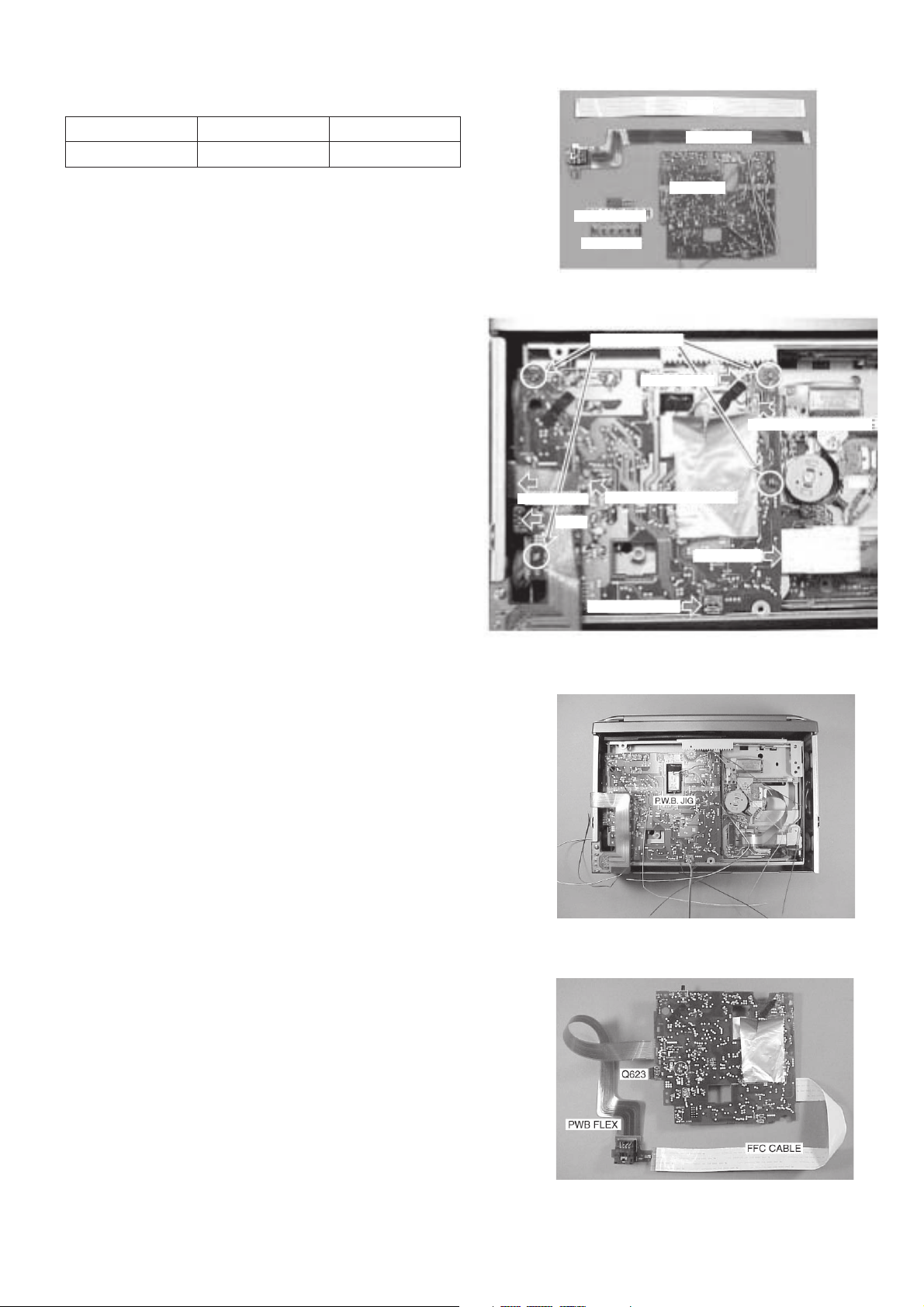
(4) Attach the parts as follows. Refer to Fig-4.
1) Attach the supplied transistor to the location of the
MAIN C.B from which Q623 is removed in the
previous paragraph.
2) Connect the supplied P.W.B. FLEX to CON1.
• When the CONTROL UNIT is not going to be
used, use the P.W.B. KEY instead. Refer to step
(6).
3) Connect the FFC cable to CON101 and to pickup.
(The supplied FFC cannot be used because pitches
and number of pins are different.)
FLEX DIN C.B
Q623
TRANSISTOR
P.W.B. KEY
Fig-1
REMOVE SCREW
LED (LED201)
REMOVE MOTOR WIRE
REMOVE SENSOR WIRE
PICK UP C.B
SENSOR (PS201)
Fig-2
Fig-3
– 2 –
Fig-4
 Loading...