


für
Antennen - Dach-Antennen
Universal aktive Dachantenne - 72° Art.-Nr.: 150609
AIV GmbH + Co. KG – Tatschenweg 1 – 74078 Heilbronn
Telefon 07131 / 5953 0 - Telefax 07131 / 5953 639
E-mail: info@aiv.de – Internet: http://www.aiv.de

Bitte lesen Sie alle Warnungen in dieser Anleitung. Diese informieren Sie über mögliche
persönliche Schäden oder Beschädigungen von Sachwerten!
Die Installation dieses Produktes ist nur von qualifi ziertem Fachpersonal vorzunehmen.
AIV übernimmt keine Verantwortung für körperliche Schäden oder Sachschäden,
die aus dem fehlerhaften- oder unsachgemäßen Anwendungsbereich seiner Produkte entstehen.
Die Dokumentation des Umbaus ist unter Vorbehalt und kann bei abweichenden Fahrzeugversionen
variieren. Bitte vergewissern Sie sich vor dem Umbau auf die Richtigkeit.
Sicherheitshinweise Seite 2
Beschreibung Seite 3
Technische Daten Seite 3
Einbauanleitung Seite 3-5
Fragen und Antworten (FAQ) Seite 6
Garantiehinweise Seite 7
Sehr geehrter Kunde,
wir gratulieren Ihnen zum Kauf dieses hervorragenden Produktes und bedanken uns für das
entgegengebrachte Vertrauen. Wir haben diese Einbauanleitung unter Berücksichtigung
der mechanischen Gegebenheiten mit größter Sorgfalt erstellt. Trotzdem können Fehler
nicht vollständig ausgeschlossen werden. Für Mitteilungen eventueller Fehler
sind wir Ihnen sehr dankbar.
Mit freundlichem Gruß,
Ihr AIV-Team
Sicherheitshinweise für den Anwender
- 2 -
Technische Daten
Aktive Universal Dachantenne mit fl exiblem abnehmbaren Antennenstab und 150 Ohm Antennen-Anschluss.
Farbe: schwarz
Teleskoplänge: 36,5 cm
Bohrloch: Ø 11 mm
Kabellänge: 40 cm mit HC97-Antennenstecker (RAKU)
Stabmaterial: Fiberglas
Stromversorgung: 12 VDC / 40 mA
Verstärkung: UKW 10 dB, LMK 16 dB
Frequenzbereich: UKW (FM) 87,5 - 108 MHz
LW (AM) 145 - 300KHz
MW (AM) 525 - 1650 KHz
KW (AM) 5950 - 6200 KHz
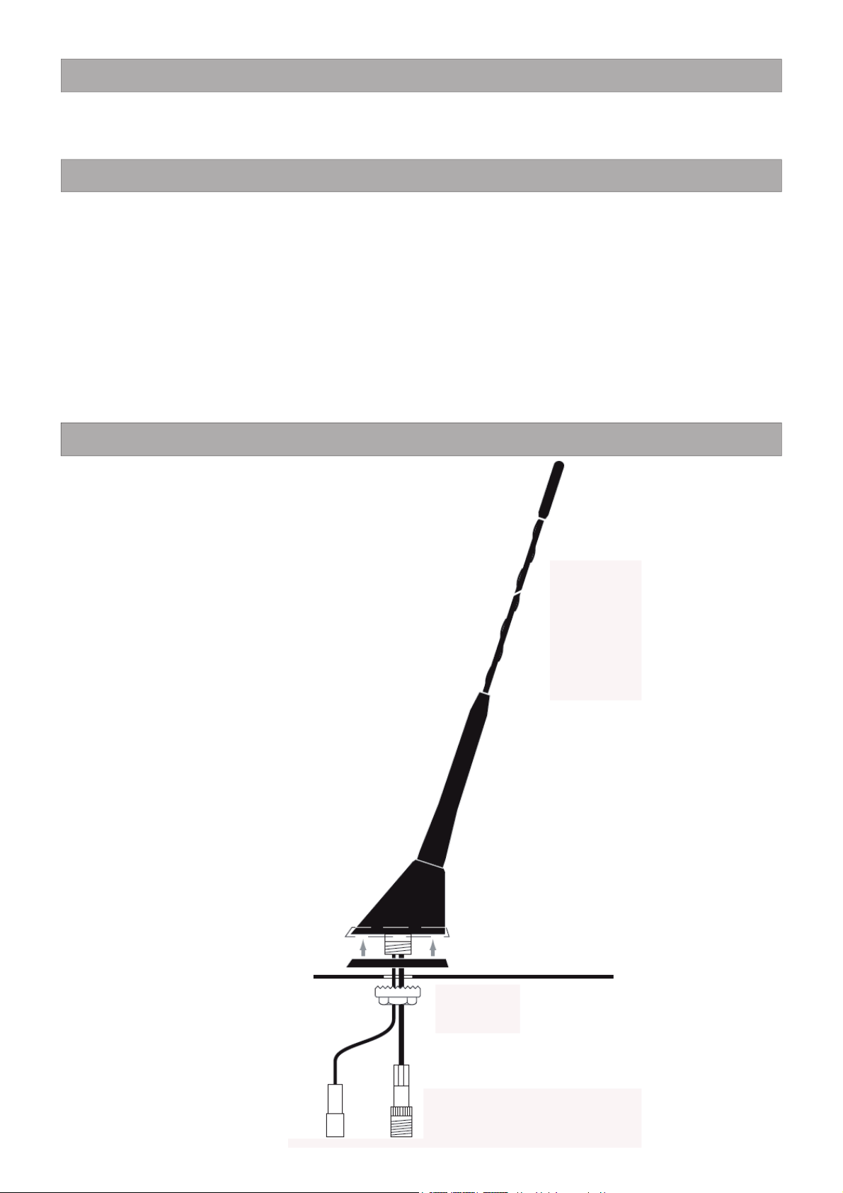
Antennenstab (a)
Antennenfuß (b)
DichtungsUnterlage (c)
Antennenkabel (e)
Sechskanntmutter
mit Zahnkranz (g)
Karosserie
Stromkabel (f)
- 4 -
Erstinstallation
1. Die Innenverkleidung im Dach am Einbauort lösen. Um den
„Himmel“ zu lösen, muss je nach Fahrzeugtyp zuerst die Seitenverkleidung (C-Säule) abgenommen werden.
2. Den Lack auf der Innenseite des Antennenloches entfernen, um
eine Masseverbindung der Antenne zu gewährleisten. Um Korrosion vorzubeugen, das Metall mit Karosserieschutzfett benetzen.
3. Die Dichtungsunterlage (c) an der vorhandenen Nase des Antennenfußes ( b) einhängen. Den Rand der Dichtungsunterlage (c)
vorsichtig über den Antennenfuß (b) stülpen.
4. Antennenfuß (b) mit Dichtungsunterlage (c) und Antennekabel (e)
mit Stromkabel (f) von außen in das Antennenloch stecken.
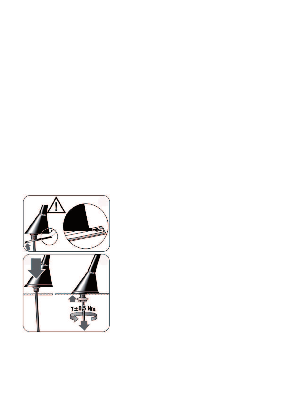
5. Die Sechskantmutter mit Zahnkranz (g) über das Antennenkabel
(e) ziehen und an den Antennenfuß (b) leicht befestigen.
6. Wenn die Dichtungsunterlage (c) und Antennenfuß (b) richtig
sitzt, kann die Sechskanntmutter mit Zahnkranz (e) mit einem
Schraubenschlüssel 22 mm mit 7 nM angezogen werden.
7. Antennenkabel (e) und Stromkabel (f) der Antenne mit dem vorhandenen Kabel * im Dach verbinden.
8. Radioempfang überprüfen.
9. Verkleidungen wieder anbringen.
10. Verkleidungsteile wieder anbringen.
* Ist kein Antennenkabel vorhanden, so sollte ein Antennenkabel am
Dach bis vor zur A-Säule zum Radio verlegt werden. Es ist darauf zu achten, dass das Kabel nicht gestreckt, gequatscht oder
geknickt wird. Der Abstand zu anderen Kabel im Fahrzeug sollte
möglicht groß sein.
Bei Verwendung eines Nachrüstradios, muß entweder ein Phan-
tomspeiseadapter installiert, oder ein separates Stromkabel zur
Antenne verlegt werden. Der Anschluss des Stromkabels erfolgt
jeweilig am Remote-Ausgang des Nachrüst Radios.
zu 5.
zu 6. zu 8.

- 5 -
Antennentausch
1. Die Innenverkleidung im Dach am Einbauort lösen. Um den „Himmel“ zu lösen, muss je nach Fahr-
zeugtyp zuerst die Seitenverkleidung (C-Säule) abgenommen werden.
2. Schraub.- bzw. Steckverbindung des Antennenkabels trennen und Befestigungsmutter der auszubauenden Antenne lösen.
3. Antenne mit Fuß von außen entnehmen.
4. Wichtig: Ist ein quatratisches Antennenloch vorhanden, dann vor der Montage das im Lieferumfang
befindliche quatratische Gummi-Adapterstück (Var I) über die Gewindeachse der Antenne schieben.
Bei Rundloch den runden Gummi-Ring (Var II) einsetzen.
5. Die Dichtungsunterlage (c) an der vorhandenen Nase des Antennenfußes ( b) einhängen. Den Rand
der Dichtungsunterlage (c) vorsichtig über den Antennenfuß (b) stülpen.
6. Antennenfuß (b) mit Dichtungsunterlage (c) und Antennekabel (e) mit Stromkabel (f) von außen in
das Antennenloch stecken.
7. Die Sechskantmutter mit Zahnkranz (g) über das Antennenkabel (e) ziehen und an den Antennenfuß
(b) leicht befestigen.
8. Wenn die Dichtungsunterlage (c) und Antennenfuß (b) richtig sitzt, kann die Sechskanntmutter mit
Zahnkranz (e) mit einem Schraubenschlüssel 22 mm mit 7 nM angezogen werden.
9. Antennenkabel (e) und Stromkabel (f) der Antenne mit dem vorhandenen Kabel im Dach verbinden.
10. Radioempfang überprüfen.
11. Verkleidungen wieder anbringen.

- 6 -
Frage Antwort
schlechter Radio-Empfang
Überprüfen, ob das verlegte Antennenkabel
nicht gequetscht oder geknickt ist.
Schraub- und Steckverbindungen von
Antenne und Kabel prüfen.
Gibt es eine Ersatzantenne (Ersatzstrahler)?
Ersatz-Antennen-Stab 40 cm: Art.-Nr.: 150254
Ersatz-Antennen-Stab 23 cm: Art.-Nr.: 150256
Ersatz-Antennen-Stab 17 cm: Art.-Nr.: 150257
Bei anderen mechanisch passenden Ersatzstrahler können sich die Empfangseigenschaften verändern.
Gibt es für diese Antenne einen Antennenverstärker?
Da die Antenne einen eingebauten Antennnenverstärker besitzt, soll kein weiterer Antennenverstärker montiert werden.
Darf ich das Antennenkabel verlängern?
Es sollte jedoch so kurz wie möglich gehaltenwerden und nur eines verwendet werden, um
Übergangsverluste gering zu halten.
Muss ich die Antenne in der Waschanlage abnehmen?
Es ist sicherer die Antenne abzunehmen um evl.
Beschädiung zu vermeiden.
Habe extrem schwankenden Empfang während der Fahrt
Bitte alle Steck- und Schraubverbindungen überprüfen.
Befestigung der Antenne prüfen. (Massekontakt)
Empfang kann je nach topografi schen Bedingungen schwanken. (Abschattungen / Refl ektionen)

AIV GmbH + Co. KG gewährleistet innerhalb der gesetzlichen Frist von 2 Jahren ab Datum des Erstkaufes, dass dieses Produkt frei von Materialfehlern und Verarbeitungsfehlern ist, sofern dieses Produkt
unter normalen Bedingungen eingesetzt und benutzt wird. Sollten Reparaturen durch Verarbeitungsfehler oder Fehlfunktionen des Produktes innerhalb der Gewährleistungsfrist nötig sein, wird die AIV GmbH
+ Co. KG das Produkt reparieren oder durch ein kostenfreies gleichwertiges Produkt ersetzen. Um die
Gewährleistung in Anspruch zu nehmen übergeben Sie das defekte Produkt und eine Kopie des
Kaufnachweises an Ihren AIV Händler. Die Gewährleistung kann nur auf den Erstkauf des Produktes
angewendet werden und ist nicht übertragbar.
Die Gewährleistung umfasst nicht:
- AIV Produkte, welche durch Unfall oder unsachgemäßen Gebrauch beschädigt
wurden
- AIV Produkte, welche durch Fremdpersonen repariert oder verändert wurden
- AIV Produkte, welche durch Fahrlässigkeit, unsachgemäßen Anschluss oder
Installation oder durch Benutzung in der Art, für welche das Produkt eigentlich
nicht gedacht ist, beschädigt wurden
Diese Anleitung ist urheberrechtlich geschützt. Jede Vervielfältigung, bzw. jeder Nachdruck,
auch auszugsweise, und jede Wiedergabe der Abbildungen, auch in verändertem Zustand,
ist nur mit der schriftlichen Zustimmung der Firma AIV GmbH + Co. KG gestattet.
© Copyright 2013 bei AIV GmbH + Co. KG
Technische Änderungen vorbehalten. Alle Angaben ohne Gewähr
- 7 -

for
Antennas - Roof Antennas
Active Universal Roof Antenna - 72° Art. no.: 150609
AIV GmbH + Co. KG – Tatschenweg 1 – 74078 Heilbronn
Phone 07131 / 5953 0 - Fax 07131 / 5953 639
Email: info@aiv.de – Internet: http://www.aiv.de

- 2 -
Read all warnings in this manual. They inform you with regard to personal injuries and damages!
This product should only be installed by a qualifi ed technician.
AIV does not assume any responsibility for bodily injury or damages to property resulting from faulty
or improper areas of application of its products.
Modifi cation documentation with reservations and can vary for different vehicle versions. Please
ensure correctness before modifi cation.
Safety Information page 2
Description page 3
Technical Specifi cations page 3
Installation Instructions page 3-5
FAQs page 6
Warranty Information page 7
Dear Customer,
congratulations on purchasing this excellent product and thank you for your trust. We created theses
installation instructions with the greatest possible care and considering the mechanical facts. However,
errors cannot be completely excluded. Please contact us in case of errors.
Best regards,
Your AIV team

- 3 -
Technical Specifi cations
Active universal roof antenna with fl exible, removable antenna rod and 150 Ohm antenna connection.
Color: Black
Telescopic length: 36.5 cm
Drill hole: Ø 11 mm
Cable length: 40 cm with HC97 antenna connector (RAKU)
Rod material: Fiberglass
Power supply: 12 V DC / 40 mA
Gain: UKW 10 dB, LMK 16 dB
Frequency range: UKW (FM) 87.5 - 108 MHz
LW (AM) 145 - 300 kHz
MW (AM) 525 - 1650 KHz
KW (AM) 5950 - 6200 KHz
Antenna rod (a)
Antenna base (b)
Sealing
support ring (c)
Antenna cable (e)
Hexagon nut with
sprocket (g)
Body
Power cable (f)

- 4 -
Initial installation
1. Loosen the interior trim in the roof at the installation location. In
order to loosen the “headliner”, fi rst the side panel (C column),
depending on the type of vehicle, must be removed.
2. Remove the paint from the inside of the antenna hole in order to
ensure the antenna is properly grounded. Place some protective
grease on the metal to protect against corrosion.
3. Hang the seal support (c) on the existing nose of the antenna
base (b). Carefully put the edge of the sealing support ring (c)
over the antenna base (b).
4. Insert the antenna base (b) with sealing support ring (c) and
antenna cable (e) with power cable (f) into the antenna hole from
the outside.
5. Pull the hexagon nut with sprocket (g) over the antenna cable (e)
and lightly secure to the antenna base (b).
6. If the sealing support ring (c) and antenna base (b) are sitting
properly, the hexagon nut with sprocket (e) can be tightened with
a 22 mm, 7 nM wrench.
7. Connect the antenna cable (e) and power cable (f) of the
antenna with the existing cable in the roof.
8. Verify radio reception.
9. Replace the paneling again.
10. Replace the cladding again.
* If there is no antenna cable available, then an antenna cable
should be installed on the roof from right up to the A column
to the radio. It is important to ensure that the cable does not
become stretched, crimped or kinked. The distance to other
cables in the vehicle should be as great as possible.
When using a retrofi t car radio, either a phantom power adapter
must be installed or a separate power cable must be laid to the
antenna. The power cable is connected at the respective remote
output of the retrofi t car radio.
To no. 5.
To no. 6. To no. 8.

- 5 -
Replacing the antenna
1. Loosen the interior trim in the roof at the installation location. In order to loosen the “headliner”, fi rst
the side panel (C column), depending on the type of vehicle, must be removed.
2. Separate the screw or plug connection of the antenna cable and loosen the fastening nut of the
antenna to be removed.
3. Remove the antenna with base from the outside.
4. Important: If a square antenna hole is available, then push the supplied square rubber adapter piece
(Var. I) over the threaded axle of the antenna prior to installation. For a round hole, use the round
rubber ring (Var. II).
5. Hang the seal support (c) on the existing nose of the antenna base (b). Carefully put the edge of the
sealing support ring (c) over the antenna base (b).
6. Insert the antenna base (b) with sealing support ring (c) and antenna cable (e) with power cable (f)
into the antenna hole from the outside.
7. Pull the hexagon nut with sprocket (g) over the antenna cable (e) and lightly secure to the antenna
base (b).
8. If the sealing support ring (c) and antenna base (b) are sitting properly, the hexagon nut with
sprocket (e) can be tightened with a 22 mm, 7 nM wrench.
9. Connect the antenna cable (e) and power cable (f) of the antenna with the existing cable in the roof.
10. Verify radio reception.
11. Replace the paneling again.

- 6 -
Question Answer
poor radio reception
Verify that the installed antenna cable is not
crimped or bent.
Check the screw and plug connections of the
antenna and cable.
Is there a spare antenna (spare body)?
Spare antenna rod, 40 cm: Art. no.: 150254
Spare antenna rod, 23 cm: Art. no.: 150256
Spare antenna rod, 17 cm: Art. no.: 150257
The reception properties could vary with other
mechanically matching spare bodies.
Is there an antenna amplifi er for this antenna?
Since the antenna has a built-in antenna amplifi er,
no additional antenna amplifi ers must be
mounted.
May I extend the antenna cable?
It should be kept as short as possible and only
one should be used in order to keep losses of
contact at a minimum.
Do I have to remove the antenna in the car wash?
It is safer to remove the antenna in order to avoid
possible damages.
I have fl uctuating reception while driving.
Please check all plug and screw connections.
Check the mounting of the antenna.
(ground contact)
The reception could fl uctuate depending on
topographical conditions. (shadowing / refl ections)

- 7 -
Warranty
AIV GmbH + Co. KG guarantees within the statutory period of 2 years from purchase date that this
product is free of material and processing defects if this product is installed and used under normal
conditions. AIV GmbH + Co. KG will repair or exchange the product free of charge if repairs due to
material or processing defects should be necessary during the warranty period. For warranty claims
return the product, accompanied by your proof of purchase, to your AIV dealer. The warranty only applies
for the original purchaser and is not negotiable.
The warranty does not cover:
! AIV products, which become damaged as a result of an accident or improper use
! AIV products, which were repaired or modifi ed by third parties
! AIV products, which are damaged due to negligence, incorrect connection or installation or
unintended use
This manual is protected by copyright. Any reproduction, even in part, and any reproduction of the
illustrations, even if modifi ed, is only permitted with the express written consent of AIV GmbH + Co. KG.
© Copyright 2013 by AIV GmbH + Co. KG
Subject to technical modifi cations. All specifi cations subject to correction
 Loading...